HEAT EXCHANGER
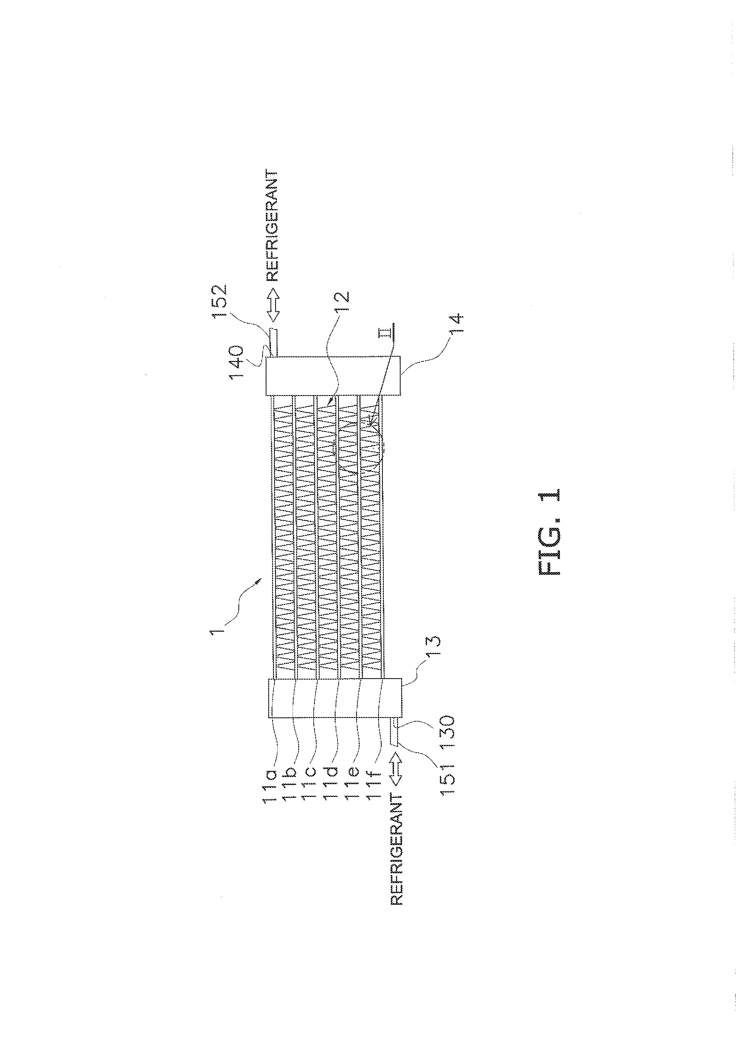
The present invention relates to a heat exchanger. Conventionally, there has been proposed a layered heat exchanger which, like the one described in patent citation 1 (JP-A No. 2006-284133), is equipped with headers that extend in a vertical direction and plural flat tubes that extend in a direction orthogonal to the length of the headers and are inserted into the headers, with the heat exchanger performing heat exchange between refrigerant flowing through plural holes formed in the flat tubes and air flowing outside the flat tubes in a width direction (transverse direction) of the flat tubes. In a heat exchanger like the one described in patent citation 1 (JP-A No. 2006-284133), improving the pressure-resistant strength is required in a case where, for example, high-pressure refrigerant (e.g., CO2 refrigerant) flows through it. As a measure for improving the pressure-resistant strength of the headers, reducing the diameter of the headers themselves is conceivable. However, when the diameter of the headers themselves is reduced, the width of the flat tubes is reduced in accompaniment therewith, so there is concern that this will have an impact on the performance of the heat exchanger. On the other hand, when the diameter of the headers is designed to match the width of the flat tubes, there is concern that the diameter of the headers will be unable to be reduced, which is not preferred from the standpoint of improving the pressure-resistant strength. Further, in a heat exchanger of this configuration in which the flat tubes are inserted into the inside space of the headers through which the refrigerant mainly travels, there is concern that the pressure loss of the refrigerant will occur inside the headers. Thus, the object of the present invention is to provide a heat exchanger that can achieve both improving the pressure-resistant strength of the headers and suppressing the pressure loss of the refrigerant. A heat exchanger pertaining to a first aspect of the present invention is equipped with a pair of headers and plural flat tubes. The headers extend in an up-and-down direction and refrigerant flows inside them. The plural flat tubes extend in a direction intersecting a longitudinal direction of the headers and are connected to the headers at different height positions. Each of the headers has a first member and a flat tube holding member. The first member has formed therein a main flow path and refrigerant connection flow paths. The main flow path extends in the up-and-down direction and refrigerant flows through it. The refrigerant connection flow paths extend from the main flow path to an end surface in the direction in which the flat tubes are positioned in order to circulate the refrigerant between the main flow path and plural refrigerant flow paths formed in the flat tubes. End portions of the flat tubes are adhered to the flat tube holding member, and the flat tube holding member holds the flat tubes. Additionally, intermediate flow paths that interconnect the refrigerant connection flow paths and the plural refrigerant flow paths in the flat tubes are formed in the headers and/or the flat tubes. Here, for example, when a heat exchanger is given a configuration in which the flat tubes are inserted into the headers, there is concern that the pressure loss of the refrigerant will occur. Thus, in the heat exchanger pertaining to the first aspect of the present invention, the flat tubes are held using the flat tube holding member that is separate from the first member having formed therein the main flow path through which the refrigerant flows. That is, a configuration in which the flat tubes are not inserted into the main flow path is employed. Because of this, the pressure loss of the refrigerant can be suppressed. Because of the refrigerant connection flow paths and the intermediate flow paths that are separate from the main flow path, the refrigerant flowing through the main flow path flows to the refrigerant flow paths in the flat tubes. Further, when this configuration is employed, the diameter of the main flow path does not have to match the width of the flat tubes because the flat tubes do not have to be inserted into the main flow path. Therefore, the diameter of the section of the main flow path through which the refrigerant travels can be reduced and the pressure-resistant strength can be improved. A heat exchanger pertaining to a second aspect of the present invention is the heat exchanger pertaining to the first aspect of the present invention, wherein the width of the intermediate flow paths is equal to or less than the width of the flat tubes. In the heat exchanger pertaining to the second aspect of the present invention, the width of the intermediate flow paths is equal to or less than the width of the flat tubes, so the longitudinal direction end surfaces of the flat tubes come into contact with the peripheries of intermediate flow path forming portions forming the intermediate flow paths. Because of this, the positioning of the flat tubes can be performed easily. A heat exchanger pertaining to a third aspect of the present invention is the heat exchanger pertaining to the first aspect or the second aspect of the present invention, wherein each of the headers further has a second member that is sandwiched between the first member and the flat tube holding member. Additionally, in a case where the intermediate flow paths are formed in the headers and the flat tubes or the headers, the intermediate flow paths are formed in the second member. In the heat exchanger pertaining to the third aspect of the present invention, both improving the pressure-resistant strength of the headers and suppressing the pressure loss of the refrigerant can be achieved. A heat exchanger pertaining to a fourth aspect of the present invention is the heat exchanger pertaining to any of the first aspect to the third aspect of the present invention, wherein in a case where L1 is the length, in a direction orthogonal to a longitudinal direction of the first member, of a main flow path forming portion forming the main flow path, π is pi, g is gravitational acceleration, m is the circulating volume of the refrigerant in a gas-liquid two-phase state flowing through the main flow path, x is inlet quality, which is the ratio of the mass flow rate of the refrigerant in a gas-phase state with respect to the total mass flow rate of the refrigerant in a gas-liquid two-phase state inside an inlet header among the pair of headers into which the refrigerant flows from outside, ρG is the density of the refrigerant in a gas-phase state flowing through the main flow path, D is the distance between the uppermost flat tube and the lowermost flat tube, and C1 and C2 are constants, the relationship of holds true. Additionally, C1=0.16 and C2=1.5. In the heat exchanger pertaining to the fourth aspect of the present invention, when L1 is decided in such a way that the above-described relationship holds true, it is easy to equally divide the refrigerant flowing through the main flow path to the refrigerant connection flow paths. That is, it becomes easier for the refrigerant flowing through the main flow path to flow equally to the refrigerant flow paths in the flat tubes connected to the refrigerant connection flow paths. A heat exchanger pertaining to a fifth aspect of the present invention is the heat exchanger pertaining to any of the first aspect to the third aspect of the present invention, wherein in a case where L1 is the length, in a direction orthogonal to a longitudinal direction of the first member, of a main flow path forming portion forming the main flow path, π is pi, g is gravitational acceleration, m is the circulating volume of the refrigerant in a gas-liquid two-phase state flowing through the main flow path, x is inlet quality, which is the ratio of the mass flow rate of the refrigerant in a gas-phase state with respect to the total mass flow rate of the refrigerant in a gas-liquid two-phase state inside an inlet header among the pair of headers into which the refrigerant flows from outside, ρG is the density of the refrigerant in a gas-phase state flowing through the main flow path, D is the distance between the uppermost flat tube and the lowermost flat tube, and C1 and C2 are constants, the relationship of holds true. Additionally, C1=0.24 and C2=1.1. In the heat exchanger pertaining to the fifth aspect of the present invention, when L1 is decided in such a way that the above-described relationship holds true, it is easy to more equally divide the refrigerant flowing through the main flow path to the refrigerant connection flow paths. That is, it becomes easier for the refrigerant flowing through the main flow path to flow more equally to the refrigerant flow paths in the flat tubes connected to the refrigerant connection flow paths. A heat exchanger pertaining to a sixth aspect of the present invention is the heat exchanger pertaining to the third aspect of the present invention and is further equipped with a securing member. The securing member is sandwiched between the flat tube holding member and the second member and secures the end portions of the plural flat tubes together with the flat tube holding member. In the heat exchanger pertaining to the sixth aspect of the present invention, the flat tubes can be more stably secured. A heat exchanger pertaining to a seventh aspect of the present invention is the heat exchanger pertaining to the third aspect or the sixth aspect of the present invention, wherein the second member and the securing member have flat panel shapes. In the heat exchanger pertaining to the seventh aspect of the present invention, for example, in the case of securing the flat tubes by forming holes in the securing member and putting the flat tubes into those holes, construction is easy to execute because the securing member with a flat panel shape enables that the holes can be formed all at once in the securing member. Further, likewise in the case of forming the intermediate flow paths in the second member also, construction is easy to execute because the holes can be formed all at once in the second member. A heat exchanger pertaining to an eighth aspect of the present invention is the heat exchanger pertaining to any of the third aspect, the sixth aspect, and the seventh aspect of the present invention, wherein the flat tube holding member covers the second member or the second member and the securing member from outside, and both ends of the flat tube holding member are in contact with and brazed to the first member. In the heat exchanger pertaining to the eighth aspect of the present invention, the second member and the securing member can be easily secured by the flat tube holding member. A heat exchanger pertaining to a ninth aspect of the present invention is the heat exchanger pertaining to any of the first aspect to the eighth aspect of the present invention, wherein plural holes are formed in the flat tube holding member. Here, for example, in the case of connecting the flat tube holding member and the flat tubes and connecting the flat tube holding member and the second member, a flux is applied. Thereafter, in the case of connecting these by brazing or the like, it is assumed that the flux will volatilize. Thus, in the heat exchanger pertaining to the ninth aspect of the present invention, the plural holes are formed in the flat tube holding member. Because of this, volatilized gas can be removed. Consequently, airtightness between connected members can be ensured. A heat exchanger pertaining to a tenth aspect of the present invention is the heat exchanger pertaining to any of the first aspect to the ninth aspect of the present invention, wherein the length, in a direction orthogonal to a longitudinal direction of the first member, of a main flow path forming portion forming the main flow path is smaller than the width of the flat tubes. In the heat exchanger pertaining to the tenth aspect of the present invention, the length, in the direction orthogonal to the longitudinal direction of the first member, of the main flow path forming portion forming the main flow path can be made smaller than the width of the flat tubes because the flat tubes do not have to be inserted into the main flow path. In the heat exchanger pertaining to the first aspect of the present invention, both improving the pressure-resistant strength of the headers and suppressing the pressure loss of the refrigerant can be achieved. In the heat exchanger pertaining to the second aspect of the present invention, the positioning of the flat tubes can be performed easily. In the heat exchanger pertaining to the third aspect of the present invention, both improving the pressure-resistant strength of the headers and suppressing the pressure loss of the refrigerant can be achieved. In the heat exchanger pertaining to the fourth aspect of the present invention, it becomes easier for the refrigerant flowing through the main flow path to flow equally to the refrigerant flow paths in the flat tubes. In the heat exchanger pertaining to the fifth aspect of the present invention, it becomes easier for the refrigerant flowing through the main flow path to flow more equally to the refrigerant flow paths in the flat tubes. In the heat exchanger pertaining to the sixth aspect of the present invention, the flat tubes can be more stably secured. In the heat exchanger pertaining to the seventh aspect of the present invention, construction is easy to execute. In the heat exchanger pertaining to the eighth aspect of the present invention, the second member and the securing member can be easily secured by the flat tube holding member. In the heat exchanger pertaining to the ninth aspect of the present invention, airtightness between connected members can be ensured. In the heat exchanger pertaining to the tenth aspect of the present invention, the length, in the direction orthogonal to the longitudinal direction of the first member, of the main flow path forming portion forming the main flow path can be made smaller than the width of the flat tubes because the flat tubes do not have to be inserted into the main flow path. A heat exchanger 1 pertaining to embodiments of the present invention will be described below with reference to the drawings. The heat exchanger 1 is a heat exchanger that uses air as a cooling source or a heating source to condense or evaporate refrigerant, and the heat exchanger 1 is, for example, employed as a heat exchanger that configures a refrigerant circuit of a vapor compression refrigeration apparatus. Here, carbon dioxide refrigerant is used as the refrigerant circulating through the refrigerant circuit. As shown in Each of the flat tubes 11 Here, six flat tubes are disposed, but the number of the flat tubes is not limited to this. The heat transfer fins 12 are corrugated fins configured from metal members made of aluminum or an aluminum alloy, and formed as a result of panel-like members being folded in corrugated shapes in their longitudinal direction. The heat transfer fins 12 are disposed in spaces sandwiched by the flat tubes 11 As shown in The headers 13 and 14 have a support function of supporting the flat tubes 11 In the description below, for convenience of description, the header on the left side in The first header 13 is a cylindrical member that has an outer peripheral portion in which an opening 130 is formed and an upper end and lower end that are closed and extends in the up-and-down direction. The opening 130 has the function of allowing the refrigerant to flow into the first header 13 or allowing the refrigerant to flow outside from the first header 13. Specifically, the opening 130 becomes an inlet for the refrigerant in a case where the heat exchanger 1 functions as an evaporator of the refrigerant and becomes an outlet for the refrigerant in a case where the heat exchanger 1 functions as a condenser of the refrigerant. The second header 14 is a tubular member that has an outer peripheral portion in which an opening 140 is formed and an upper end and lower end that are closed and extends in the up-and-down direction. The opening 140 has the function of allowing the refrigerant to flow into the second header 14 or allowing the refrigerant to flow outside from the second header 14. Specifically, the opening 140 becomes an inlet for the refrigerant in a case where the heat exchanger 1 functions as a condenser of the refrigerant and becomes an outlet for the refrigerant in a case where the heat exchanger 1 functions as an evaporator of the refrigerant. The opening 130 and the opening 140 are formed by stamping or the like. Further, pipes 151 and 152 through which the refrigerant flows are connected to the opening 130 and the opening 140. The first header 13 and the second header 14 have the same configuration. Therefore, in the description below, only the configuration of the first header 13 will be described and description of the configuration of the second header 14 will be omitted. As shown in The first member 131 is a member that extends in the vertical direction and is configured from a metal member such as clad metal comprising an aluminum alloy with a low melting point bonded to the surface of another aluminum alloy serving as a core. As shown in Specifically, the first member 131 has a first portion 331 As shown in Further, refrigerant connection flow paths 231 The flat tube holding member 132 is a member to which the end portions of the flat tubes 11 In a regularly assembled state, the flat tube holding member 132 is bent inward in such a way as to cover both width direction end portions of the second portion 331 As shown in In a state in which the flat tubes 11 As shown in The second member 133 is configured from a metal member such as clad metal (clad metal with a higher melting point than that of other members is used for the clad metal forming the second member 133) and has a long and narrow flat panel shape extending in the vertical direction. The transverse cross section of the second member 133 has a quadrilateral shape. As shown in That is, the second member 133 has the function of enabling the circulation of the refrigerant between the first member 131 having formed therein a flow path (specifically, the refrigerant main flow path 131 The height of the intermediate flow paths 133 Further, a width W3 of the intermediate flow paths 133 A method of manufacturing the heat exchanger 1 will be described below. In the description below also, description of the second header 14 will be omitted. First, the first member 131 is formed. Specifically, a long and narrow cylinder-shaped member having an open space (specifically, the refrigerant main flow path 131 Next, the second member 133 is formed. Specifically, plural holes (specifically, the intermediate flow paths 133 Next, holes (specifically, the flat tube-use holes 132 Next, the first member 131, the second member 133, the flat panel-shaped clad metal having formed therein the holes for holding the flat tubes 11 Then, the flat panel-shaped clad metal is bent in such a way as to cover the second member 133 from outside along the shape of the second member 133, and both ends of the flat panel-shaped clad metal are brought into contact with, in such a way as to cover from outside, part of the first member 131 (specifically, the second portion 331 Then, the flat tubes 11 Then, these are joined together by brazing. Here, by using clad metal for the flat tube holding member 132 and joining the flat tube holding member 132 to the flat tubes 11 The first member 131 is given a configuration in which its upper and lower ends are closed by an upper end member and a lower end member (not shown in the drawings) having the same cross-sectional shape as that of the first member 131, and the upper end member and the lower end member are joined to the first member 131 by brazing. Further, the second header 14 is joined to the other end portions of the flat tubes 11 The series of flows of the refrigerant in the heat exchanger 1 having the above configuration will be briefly described. (4-1) Flow of the Refrigerant in a Case where the Heat Exchanger 1 Functions as an Evaporator First, the refrigerant flowing toward the heat exchanger 1 from outside the first header 13 flows into the first header 13 via the opening 130. Here, the first header 13 functions as an inlet header into which the refrigerant flows from outside. The general flow of the refrigerant is such that the refrigerant that has flowed into the first header 13 travels through the refrigerant main flow path 131 More specifically, the refrigerant that has flowed into the first header 13 travels through the refrigerant main flow path 131 Then, the refrigerant that is equally divided to the refrigerant flow paths 112 flows toward the second header 14. The refrigerant that has merged inside the second header 14 flows out to the outside of the heat exchanger 1 via the opening 140. As described above, in a case where the heat exchanger 1 functions as an evaporator, the refrigerant flows through the insides of the headers 13 and 14 from the lower space to the upper space. (4-2) Flow of the Refrigerant in a Case where the Heat Exchanger 1 Functions as a Condenser In a case where the heat exchanger 1 functions as a condenser, the refrigerant flowing toward the heat exchanger 1 from outside the second header 14 flows into the second header 14 via the opening 140. Here, the second header 14 functions as an inlet header into which the refrigerant flows from outside. Then, like the flow of the refrigerant in the case where the heat exchanger 1 functions as an evaporator, the refrigerant that has flowed into the second header 14 flows toward the first header 13. The refrigerant that has merged inside the first header 13 flows out to the outside of the heat exchanger 1 via the opening 130. As described above, in a case where the heat exchanger 1 functions as a condenser, the refrigerant flows through the insides of the headers 13 and 14 from the upper space to the lower space. Here, as shown in The length L1, in the direction orthogonal to the longitudinal direction of the first member 131, of the refrigerant main flow path forming portion 13 Here, π is pi. g is gravitational acceleration [m/s2]. m is the circulating volume [kg/s] of the refrigerant in a gas-liquid two-phase state flowing through the refrigerant main flow path 131 From the above equality 1, it will be understood that the length L1 is decided by the constants C1 and C2 and the distance D. The distance D is a value unequivocally decided in accordance with the type of the headers 13 and 14. Here, the inventors of the present invention performed an experiment and discovered the constants C1 and C2 with which flow dividing ability becomes equal to or greater than a predetermined ability (in the present embodiment, 90%). “Flow dividing ability” is an ability indicating how equally the refrigerant can be allowed to flow from the refrigerant main flow path 131 In this experiment, a value calculated from expression 2 below is used as a substitute value of the constants C1 and C2 (Ugs is gas speed). This is because the relationship of equality 4 below can be derived when equality 1 above is divided by the gas speed Ugs defined from expression 3 below. Looking at the graph of Therefore, the value of L1 with which the flow dividing ability is high can be decided using equality 1 and the values of the constants C1 and C2 derived from the graph of For example, in a case where D is 500 mm, the evaporation temperature is 7° C. (ρG decided from this evaporation temperature becomes 122.3 kg/m3), x is 0.15, and m is 100 kg/hr, it suffices to design L1 in such a way that L1 becomes 3.6 mm to 11.0 mm if one wants to obtain a flow dividing ability of 90%, and it suffices to design L1 in such a way that L1 becomes 4.2 to 9.0 mm if one wants to obtain a flow dividing ability of 95%. (6-1) For example, in a case where the flat tubes are inserted into the inside spaces of the headers through which the refrigerant mainly travels, there is concern that the pressure loss of the refrigerant will occur. Further, in a heat exchanger of this configuration, when joining together the flat tubes and the headers, it is assumed that brazing filler metal will flow into the headers from the end portions of the flat tubes. In this case, there is concern that the flow path through which the refrigerant mainly travels will end up being blocked as a result of brazing filler metal clogs or the like occurring. Thus, in the present embodiment, the plural flat tubes 11 Further, by employing this configuration, the diameter of the first header 13 and the refrigerant main flow path 131 (6-2) In the present embodiment, the second member 133 has a flat panel shape. Holes can be formed easily in the second member 133, so the intermediate flow paths 133 (6-3) The width W3 of the intermediate flow paths 133 (6-4) In the present embodiment, the width W3 of the intermediate flow path forming portions 134 (6-5) In the present embodiment, the flat tube holding member 132 covers the second member 133 from outside, and both ends of the flat tube holding member 132 are in contact with and joined by brazing to the first member 131. Here, the second member 133 can be easily secured by the flat tube holding member 132. Further, in the present embodiment, the inwardly bent end portions of the flat tube holding member 132 are positioned in the recessed portion spaces S formed by the first portion 331 Here, because the recessed portion spaces S are formed by the first portion 331 (6-6) In the present embodiment, clad metal different from other members (the flat tube holding member 132) is used for the second member 133. Specifically, the clad metal used for the second member 133 has a higher melting point than that of the clad metal used for other members. This is to ensure that the brazing filler metal of the second member 133 does not flow to the end surfaces of the flat tubes 11 (6-7) In the present embodiment, the first member 131, the second member 133, and the flat tube holding member 132 are configured from clad metal, so it is not necessary to use separate brazing filler metals when a constructor brazes these. Therefore, the number of man-hours in the brazing work can be reduced and costs can be suppressed. (6-8) In the present embodiment, the length L1, in the direction orthogonal to the longitudinal direction of the first member 131, of the refrigerant main flow path forming portion 13 An embodiment of the present invention has been described above on the basis of the drawings, but the specific configurations thereof are not limited to those in the above-described embodiment and can be changed without departing from the gist of the invention. In the above-described embodiment, only the flat tube-use holes 132 In addition to the flat tube-use holes 132 Here, although it is not mentioned above, when joining together the flat tube holding member 132 and the flat tubes 11 Therefore, by forming the plural holes 232 In the above-described embodiment, the second member 133 is described as being disposed between the first member 131 and the flat tube holding member 132, but the present invention is not limited to this and the second member 133 does not have to be disposed. That is, a configuration in which the end surface of the first member 131 on the flat tube holding member side and the end surface of the flat tube holding member 132 on the first member side are in contact with each other may also be employed. In modifications 1C to 1G below, employable configurations of the headers 13 and 14 (below, only the first header 13 is indicated) and the flat tubes 11 In the heat exchanger 1 pertaining to the present modification 1C, as shown in In the heat exchanger 1 pertaining to the present modification 1C, even in a case where the second member 133 is not disposed between the first member 131 and the flat tube holding member 132, effects that are the same as those of the above-described embodiment can be expected because the recessed portion 234 In the heat exchanger 1 pertaining to the present modification 1D, as shown in Therefore, in the heat exchanger 1 pertaining to the present modification 1D, even in a case where the second member 133 is not disposed between the first member 131 and the flat tube holding member 132, effects that are the same as those of the above-described embodiment can be expected because the recessed portions 254 In the heat exchanger 1 pertaining to the present modification 1E, as shown in In the heat exchanger 1 pertaining to the present modification 1E, even in a case where the second member 133 is not disposed between the first member 131 and the flat tube holding member 132, effects that are the same as those of the above-described embodiment can be expected because the recessed portions having the function of the intermediate flow paths 133 In the heat exchanger 1 pertaining to the present modification 1F, as shown in Further, the corner portions of the flat tubes 11 As described above, in the heat exchanger 1 pertaining to the present modification 1F, even in a case where the second member 133 is not disposed between the first member 131 and the flat tube holding member 132, effects that are the same as those of the above-described embodiment can be expected because the space S1 functions as the intermediate flow paths 133 In the heat exchanger 1 pertaining to the present modification 1G, as shown in As described above, in the heat exchanger 1 pertaining to the present modification 1G, because of the convex portions 171, the positioning of the flat tubes 11 In the above-described embodiment, the length, in the direction orthogonal to the longitudinal direction of the headers 13 and 14, of the refrigerant main flow path forming portions forming the refrigerant main flow paths in the headers 13 and 14 is the same from the upper ends to the lower ends of the headers 13 and 14, but the present invention is not limited to this. For example, the length of the header through which liquid refrigerant flows may also be made smaller than the length of the header through which gas refrigerant flows. Because of this, a drop in the refrigerant flow speed of the liquid refrigerant can be suppressed and the flow dividing ability can be improved. Next, a second embodiment will be described. In the description below, the same reference signs will be given to components and so forth that are the same as those in the first embodiment and description will be omitted. That which mainly differs in the second embodiment from the first embodiment is that a securing member 210 for more stably securing the flat tubes 11 As shown in As shown in The method of manufacturing the heat exchanger 1 of the second embodiment is substantially the same as that of the first embodiment simply as a result of adding, to the process of the method of manufacturing the heat exchanger 1 of the first embodiment, forming the securing member 210, joining together the second member 133 and the securing member 210, and joining together the securing member 210 and the flat tube holding member 132. (2-1) In the second embodiment, by interposing the securing member 210 between the flat tube holding member 132 and the second member 133, the flat tubes 11 (2-2) The securing member 210 has a flat panel shape as described above. Because of this, the flat tube securing holes 210 (2-3) The flat tube holding member 132 in the second embodiment covers the securing member 210 from outside in addition to the second member 133, so not just the second member 133 but also the securing member 210 can be easily secured. The present invention is applicable to a variety of heat exchangers configured from headers that extend in a vertical direction and plural flat tubes that extend in a direction orthogonal to the length of the headers and are inserted into the headers. A heat exchanger includes a pair of headers extending in an up-and-down direction to carry refrigerant, and plural flat tubes connected to the headers at different height positions and extending along a direction intersecting a longitudinal direction of the headers. Each header includes a first member and a flat tube holding member. The first member has a main flow path, and refrigerant connection flow paths to circulate refrigerant between the main flow path and plural refrigerant flow paths formed in the flat tubes. The flat tube holding member holds the flat tubes. End portions of the flat tubes are adhered to the flat tube holding member. Intermediate flow paths interconnect the refrigerant connection flow paths and the plural refrigerant flow paths in the flat tubes. The intermediate flow paths are formed in at least one of the headers and the flat tubes. 1. A heat exchanger comprising:
a pair of headers extending in an up-and-down direction, the pair of headers being configured to carry a refrigerant flow therein; and plural flat tubes connected to the headers at different height positions, the plural flat tubes extending along a direction intersecting a longitudinal direction of the headers, each of the headers including
a first member having a main flow path extending in the up-and-down direction and configured to carry the refrigerant flow therein, and refrigerant connection flow paths extending from the main flow path to an end surface in the direction intersecting the longitudinal direction in order to circulate the refrigerant flow between the main flow path and plural refrigerant flow paths formed in the flat tubes, and a flat tube holding member with end portions of the flat tubes adhered thereto, the flat tube holding member holding the flat tubes, and intermediate flow paths interconnecting the refrigerant connection flow paths and the plural refrigerant flow paths in the flat tubes, the intermediate flow paths being formed in at least one of
the headers and the flat tubes. 2. The heat exchanger according to a width of the intermediate flow paths is no more than a width of the flat tubes. 3. The heat exchanger according to each of the headers further includes a second member sandwiched between the first member and the flat tube holding member, and in a case where the intermediate flow paths are at least partially formed in the headers, the intermediate flow paths are at least partially formed in the second member. 4. The heat exchanger according to in a case where
L1 is a length in a direction orthogonal to a longitudinal direction of the first member of a main flow path forming portion forming the main flow path, π is pi, g is a gravitational acceleration, m is a circulating volume of refrigerant in a gas-liquid two-phase state flowing through the main flow path, x is an inlet quality, the inlet quality being a ratio of a mass flow rate of the refrigerant in a gas-phase state with respect to a total mass flow rate of the refrigerant in a gas-liquid two-phase state inside an inlet header of the pair of headers, the refrigerant flows from outside into the inlet header, ρG is a density of the refrigerant in a gas-phase state flowing through the main flow path, D is a distance between the uppermost flat tube and a lowermost flat tube, and C1 and C2 are constants, a relationship holds true, and
C1=0.16 and C2=1.5. 5. The heat exchanger according to in a case where
L1 is a length in a direction orthogonal to a longitudinal direction of the first member of a main flow path forming portion forming the main flow path, π is pi, g is a gravitational acceleration, m is a circulating volume of refrigerant in a gas-liquid two-phase state flowing through the main flow path, x is an inlet quality, the inlet quality being a ratio of a mass flow rate of the refrigerant in a gas-phase state with respect to a total mass flow rate of the refrigerant in a gas-liquid two-phase state inside an inlet header of the pair of headers, the refrigerant flows from outside into the inlet header, ρG is a density of the refrigerant in a gas-phase state flowing through the main flow path, D is a distance between the uppermost flat tube and a lowermost flat tube, and C1 and C2 are constants, a relationship holds true, and
C1=0.24 and C2=1.1. 6. The heat exchanger according to a securing member sandwiched between the flat tube holding member and the second member, the securing member securing the end portions of the plural flat tubes together with the flat tube holding member. 7. The heat exchanger according to the second member has a flat panel shape. 8. The heat exchanger according to the flat tube holding member covers the second member, and both ends of the flat tube holding member are in contact with and brazed to the first member. 9. The heat exchanger according to plural holes are formed in the that tube holding member. 10. The heat exchanger according to a length in a direction orthogonal to a longitudinal direction of the first member, of a main flow path forming portion forming the main flow path, is smaller than a width of the flat tubes. 11. The heat exchanger according to each of the headers further includes a second member sandwiched between the first member and the flat tube holding member, and in a case where the intermediate flow paths are at least partially formed in the headers, the intermediate flow paths are at least partially formed in the second member. 12. The heat exchanger according to in a case where
L1 is a length in a direction orthogonal to a longitudinal direction of the first member of a main flow path forming portion forming the main flow path, π is pi, g is a gravitational acceleration, m is a circulating volume of refrigerant in a gas-liquid two-phase state flowing through the main flow path, x is an inlet quality, the inlet quality being a ratio of a mass flow rate of the refrigerant in a gas-phase state with respect to a total mass flow rate of the refrigerant in a gas-liquid two-phase state inside an inlet header of the pair of headers, the refrigerant flows from outside into the inlet header, ρG is a density of the refrigerant in a gas-phase state flowing through the main flow path, D is a distance between the uppermost flat tube and a lowermost flat tube, and C1 and C2 are constants, a relationship holds true, and
C1=0.16 and C2=1.5. 13. The heat exchanger according to in a case where
L1 is a length in a direction orthogonal to a longitudinal direction of the first member of a main flow path forming portion forming the main flow path, π is pi, g is a gravitational acceleration, m is a circulating volume of refrigerant in a gas-liquid-phase state flowing through the main flow path, x is an inlet quality, the inlet quality being a ratio of a mass flow rate of the refrigerant in a gas-phase state with respect to a total mass flow rate of the refrigerant in a gas-liquid two-phase state inside an inlet header of the pair of headers, the refrigerant flows from outside into the inlet header, ρG is a density of the refrigerant in a gas-phase state flowing through the main flow path, D is a distance between the uppermost flat tube and a lowermost flat tube, and C1 and C2 are constants, a relationship holds true, and
C1=0.24 and C2=1.1. 14. The heat exchanger according to in a case where
L1 is a length in a direction orthogonal to a longitudinal direction of the first member of a main flow path forming portion forming the main flow path, π is pi, g is a gravitational acceleration, m is a circulating volume of refrigerant in a gas-liquid two-phase state flowing through the main flow path, x is an inlet quality, the inlet quality being a ratio of a mass flow rate of the refrigerant in a gas-phase state with respect to a total mass flow rate of the refrigerant in a gas-liquid two-phase state inside an inlet header of the pair of headers, the refrigerant flows from outside into the inlet header, ρG is a density of the refrigerant in a gas-phase state flowing through the main flow path, D is a distance between the uppermost flat tube and a lowermost flat tube, and C1 and C2 are constants, a relationship holds true, and
C1=0.16 and C2=1.5. 15. The heat exchanger according to in a case where
L1 is a length in a direction orthogonal to a longitudinal direction of the first member of a main flow path forming portion forming the main flow path, π is pi, g is a gravitational acceleration, m is a circulating volume of refrigerant in a gas-liquid two-phase state flowing through the main flow path, x is an inlet quality, the inlet quality being a ratio of a mass flow rate of the refrigerant in a gas-phase state with respect to a total mass flow rate of the refrigerant in a gas-liquid two-phase state inside an inlet header of the pair of headers, the refrigerant flows from outside into the inlet header, ρG is a density of the refrigerant in a gas-phase state flowing through the main flow path, D is a distance between the uppermost flat tube and a lowermost flat tube, and C1 and C2 are constants, a relationship holds true, and
C1=0.24 and C2=1.1. 16. The heat exchanger according to the second member and the securing member have flat panel shapes. 17. The heat exchanger according to the flat tube holding member covers one of
the second member and the second member and the securing member from outside, and
both ends of the flat tube holding member are in contact with and brazed to the first member. 18. The heat exchanger according to the flat tube holding member covers one of
the second member and the second member and the securing member from outside, and
both ends of the flat tube holding member are in contact with and brazed to the first member. TECHNICAL FIELD
BACKGROUND ART
SUMMARY OF INVENTION
Technical Problem
Solution to Problem
Advantageous Effects of Invention
BRIEF DESCRIPTION OF DRAWINGS
DESCRIPTION OF EMBODIMENTS
First Embodiment
(1) Configuration of Heat Exchanger 1
(1-1) Flat Tubes 11
(1-2) Heat Transfer Fins 12
(1-3) Headers 13 and 14
(2) Regarding the Specific Configuration of the Headers 13 and 14
(2-1) First Member 131
(2-2) Flat Tube Holding Member 132
(2-3) Second Member 133
(3) Regarding Method of Manufacturing the Heat Exchanger 1
(4) Flows of the Refrigerant
(5) Regarding the Refrigerant Main Flow Path 131
(6) Characteristics
(7) Modifications
(7-1) Modification 1A
(7-2) Modification 1B
(7-3) Modification 1C
(7-4) Modification 1D
(7-5) Modification 1E
(7-6) Modification 1F
(7-7) Modification 1G
(7-8) Modification 1H
Second Embodiment
(1) Securing Member 210
(2) Characteristics
INDUSTRIAL APPLICABILITY
REFERENCE SIGNS LIST
CITATION LIST
Patent Literature