INJECTION MOLDING MACHINE HAVING A TIE BAR ENGAGEMENT APPARATUS AND METHOD OF OPERATING SAME
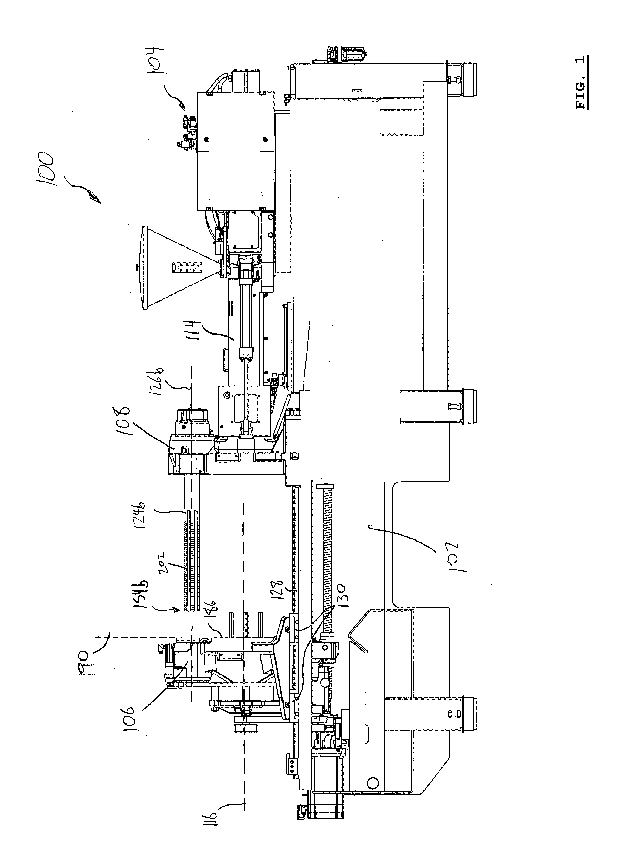
This application claims the benefit of Provisional Application Ser. No. 61/619,166, filed Apr. 2, 2012, which is hereby incorporated herein by reference. The present subject matter of the teachings described herein relates generally to injection molding machines including at least one tie bar engagement apparatus and methods of operating the same. U.S. Pat. No. 7,461,976 (Glaesener et al.) discloses a flexible shoe assembly for use in a molding system. The clamp unit of a molding system includes a moving platen and a stationary platen supported by a frame. Tie bars interconnect the moving platen with the stationary platen. The tie bars are secured to the stationary platen and pass through respective openings in the moving platen. Each tie bar is supported and guided within their respective openings by a flexible shoe assembly and wear pad. The flexible shoe assembly has a force redirector for directing force away from a peripheral edge of the wear pad towards a central force area. The flexible shoe assembly also includes a load distributor to distribute the load across the wear pad surface. The flexible shoe assembly includes an upper support that is flexible about a lower support to keep the wear pad in operational contact with the tie bar. U.S. Pat. No. 5,620,723 (Glaesener et al.) discloses an injection molding machine that includes a stationary platen including at least one stationary mold half and a first moveable platen. The first moveable platen is moveable relative to the stationary platen and has a second mold half adapted to engage the stationary mold half to for a first mold. A second moveable platen may also be provided which is moveable toward the stationary platen and includes a third mold half adapted to engage a fourth mold half included with one of the stationary platen and the first moveable platen. The third and fourth mold halves form a second mold. Each of the first and second molds having a hot runner leading thereto and an injection unit is provided for delivering melt to the hot runners of the first and second molds. The machine also includes tie bars extending between and connecting the stationary platen and the moveable platens. At least one of the first and, if used, the second moveable platen and stationary platen includes a mechanism for securing at least one of the tie bars. The mechanism for securing comprises an engagement mechanism for placing the mechanism for securing into and out of locking engagement with at least one of the tie bars such that when the engagement mechanism is out of locking engagement with the at least one tie bar, the mechanism for securing and the at least one tie bar are relatively moveable. The following summary is intended to introduce the reader to various aspects of the applicant's teaching, but not to define any invention. In general, disclosed herein are one or more methods or apparatuses related to injection molding, and to cooling injection molded articles outside the mold area of an injection molding machine. According to one aspect of the teaching disclosed herein, an injection molding machine includes (a) a base and an injection unit mounted to the base; (b) a first platen for holding a first mold section and a second platen for holding a second mold section, the first and second platens supported by the base, at least one of the first and second platens coupled to a platen actuator for moving the at least one platen relative to the other along a machine axis between mold-open and mold-closed positions, the machine axis oriented horizontally and defining a longitudinal direction parallel to the machine axis; (c) at least a first tie bar extending generally between the first and second platens for coupling together the first and second platens when in the mold-closed position, the first tie bar extending in the longitudinal direction along a first tie bar axis, the first tie bar having a fixed end secured to the second platen and a free end spaced longitudinally away from the fixed end, and the first tie bar having a first bearing surface extending longitudinally along an underside surface of the tie bar; and (d) at least a first tie bar engagement apparatus associated with the first tie bar. The first tie bar engagement apparatus includes: a first bore in the first platen for receiving the respective tie bar therethrough at least when the platens are in the mold-closed position; and a first roller mounted to the first platen proximate the first bore, the first roller comprising a first peripheral surface in rolling engagement with the first tie bar when the first tie bar is received in the first bore to support the first tie bar from beneath, the first roller rotatable about a first roller axis that is oriented horizontally and perpendicular to the machine axis, the first roller axis defining a lateral direction. In some examples, a vertical alignment plane containing the first bore axis intersects the first peripheral surface of the first roller. In some examples, the first peripheral surface may be generally cylindrical and has a lateral extent that is parallel to the first roller axis, and the lateral extent may be laterally centered about the vertical alignment plane containing the first bore axis. The first roller may exert a first support force on the first bearing surface, the first support force directed vertically upwards in lateral alignment with the first tie bar axis. The first bearing surface may be disposed in a generally horizontal bearing surface plane and the first support force exerted by the first roller may be normal to the bearing surface plane. The first peripheral surface of the first roller may provide tangential engagement with the first tie bar along a first line of engagement, the first line of engagement oriented longitudinally and in lateral alignment with the first bore axis and at a first elevation below the first bore axis. In some examples, the first platen includes a first side facing the second platen, the first side having a first mold support surface disposed in a vertical first support surface plane that is orthogonal to the machine axis, and the first roller may be set back longitudinally from the support surface plane away from the second platen such that the first peripheral surface is longitudinally shy of the first support surface plane. The first bore may have a first end directed towards the second platen, the first end set longitudinally back from the first support surface plane, and the first roller axis may be longitudinally intermediate the first end of the first bore and the first support surface plane. The first peripheral surface of the first roller may have a first roller radius, and the first roller axis may be set back longitudinally from the first support surface plane by a longitudinal offset that is greater than the first roller radius. In some examples, the first tie bar may have a plurality of outwardly protruding tie bar teeth spaced apart longitudinally along at least a portion of the first tie bar, and the first tie bar engagement apparatus may include a locking member adjacent the first bore, the locking member having inwardly directed locking teeth, the locking member moveable between a locked position in which the locking teeth engage the tie bar teeth to restrict longitudinal movement of the first tie bar relative to the first platen, and an unlocked position in which the locking teeth and tie bar teeth are disengaged and longitudinal movement of the first tie bar relative to the first platen is unrestricted by the locking member. The first bearing surface may include a first track surface on the first tie bar, the first track surface having first and second lateral sides extending longitudinally along the tie bar, the first and second lateral sides at least partially bounded by portions of the tie bar teeth extending circumferentially away from either side of the first track surface. The first lateral side of the first track surface may be at least partially bounded by a first longitudinal row of teeth and the second lateral side of the first track surface may be at least partially bounded by a second longitudinal row of teeth. The track surface may be integral with the first tie bar. In some examples, the tie bar engagement apparatus may include a second roller mounted to the first platen proximate the first bore, the second roller having a second peripheral surface for tangential engagement with the first tie bar along a second line of engagement disposed laterally away from the first bore axis and at a second elevation above the first bore axis, the second peripheral surface in rolling engagement with the first tie bar when the first tie bar is received in the first bore to exert a first laterally inward alignment force and first vertically downward alignment force on the tie bar. The tie bar engagement apparatus may further include a third roller mounted to the first platen proximate the first bore, the third roller having a third peripheral surface for tangential engagement with the first tie bar along a third line of engagement disposed laterally away from the first bore axis opposite the second line of engagement and at an elevation above the first bore axis and generally equal to the second elevation, the third peripheral surface in rolling engagement with the first tie bar when the first tie bar is received in the first bore to exert a second laterally inward alignment force and a second vertically downward alignment force on the tie bar, the second laterally inward alignment force opposite the first laterally inward alignment force. The first roller, second roller and third roller may be equally spaced apart from each other about the periphery of the first bore. According to some aspects, a platen for an injection molding machine includes: (a) a first bore in the first platen for receiving a respective tie bar therethrough, the first bore extending along a first bore axis; and (b) a first roller mounted to the first platen proximate the first bore, the first roller having a first peripheral surface for bearing against the tie bar in rolling engagement when the first tie bar is received in the first bore to support the first tie bar from beneath, the first roller rotatable about a first roller axis that is oriented horizontally and perpendicular to the first bore axis, the first roller exerting a first support force on the tie bar, the first support force directed vertically upwards in lateral alignment with the first bore axis. According to some aspects, a method of supporting a plurality of tie bars on an injection molding machine having a pair of platens and a plurality of tie bars extending between the platens includes: (a) translating the tie bars through respective bores in a first one of the platens while moving at least one of the platens relative to the other between mold-open and mold-closed positions, each bore extending longitudinally along a bore axis; and (b) during at least a portion of the translation of step (a), supporting each tie bar from underneath with a respective roller mounted to the first platen adjacent each respective bore, each respective roller rotatable about a support roller axis that is generally horizontal and disposed vertically below, and in lateral registration with, the bore axis of each respective bore. In some examples, each tie bar has a fixed end secured to the second platen and a free end spaced apart from the fixed end, and the step of translating the platens to the mold open position includes withdrawing the tie bars from the bores of the first platen. In some examples, translating the platens from the mold-open position towards the mold-closed position includes moving the free end of each respective tie bar from a roller-disengaged position in which the free end of the tie bar is below vertical alignment with the respective bore, into a roller-engaged position in which the free end of the tie bar is raised into vertical alignment with the respective bore by engagement with the respective roller. Other aspects and features of the present specification will become apparent, to those ordinarily skilled in the art, upon review of the following description of specific examples of the teaching disclosed herein. The drawings included herewith are for illustrating various examples of articles, methods, and apparatuses of the teaching of the present specification and are not intended to limit the scope of what is taught in any way. In the drawings: Various apparatuses or processes will be described below to provide an example of an embodiment of each claimed invention. No embodiment described below limits any claimed invention and any claimed invention may cover processes or apparatuses that differ from those described below. The claimed inventions are not limited to apparatuses or processes having all of the features of any one apparatus or process described below or to features common to multiple or all of the apparatuses described below. It is possible that an apparatus or process described below is not an embodiment of any claimed invention. Any invention disclosed in an apparatus or process described below that is not claimed in this document may be the subject matter of another protective instrument, for example, a continuing patent application, and the applicants, inventors or owners do not intend to abandon, disclaim or dedicate to the public any such invention by its disclosure in this document. Referring to In the example illustrated, the injection molding machine 100 is a two-platen type injection molding machine. In this configuration, the first platen 106 is a moving platen that can slide or translate in an axial direction along the base (i.e. in the direction of the machine axis 116), towards and away from the second platen 108, which is stationary in the example illustrated. The machine axis 116 is horizontal in the example illustrated, and defines a longitudinal direction. Referring to Any suitable platen actuator or apparatus can be used to axially translate the first platen 106 relative to the second platen 108. In the illustrated example, a platen actuator 122, including a motor and ball screw, is provided to facilitate moving the first platen 106 between open and closed positions relative to the stationary platen 108 during each molding cycle carried out by the injection molding machine. One or more connecting members can extend between the first and second platens 106 and 108 for coupling together the first and second platens when in the mold-closed position. Referring to The first platen 106 may be slidingly supported on any suitable apparatus, including, for example a rail 128 on the injection molding machine 100. Referring to Referring to In the example illustrated, the first platen 106 includes a plurality of tie bar connection bosses 132, including bosses 132 Each bore 138 is sized and shaped to slidingly receive a corresponding tie bar 124. In the illustrated example, the tie bars 124 have generally circular cross-sectional areas and each bore 138 is configured as a generally cylindrical passage extending through the first platen 106. Alternatively, the tie bar connection bosses 132 and/or bores 138 may be of any suitable configuration that can accommodate a respective tie bar shape, and may be positioned at any suitable location on the first platen 106. In other examples, the tie bars 124 can be fixed to, and moveable with, the moving platen 106, and can be slidingly received within corresponding bosses and bores (having some or all of the features described herein) provided on the stationary platen. Referring to Referring to To help support at least some of the weight of the tie bars 124, tie bar engagement apparatuses can include support members. Optionally, the tie bar support members can be mounted to the first platen 106 and can be movable with the first platen 106. In this configuration, at least some of the weight of the tie bars 124 can be transferred to the first platen 106 via the tie bar support members, and in turn to the machine base 102 via the first platen 106. Optionally, the tie bar engagement apparatuses can be configured to remain engaged with the tie bars 124 throughout a complete molding cycle of the injection molding machine. For example, the rollers 160 can be in contact with the tie bars 124 when the first platen 106 is in the closed position ( In configurations where the tie bar engagement apparatuses remain engaged while the first platen 106 is moved relative to the tie bars, it may be desirable to reduce the friction between the tie bars 124 and the tie bar engagement apparatuses. This may help reduce wear and/or resistance when the first platen 106 is moved relative to the tie bars. Optionally, the tie bar engagement apparatuses may include one or more wheel, roller or other type of rotatable apparatus that can be in rolling contact with the tie bars, instead of engaging the tie bars in sliding contact during axial movement of the first platen. The use of a rotary support member may help reduce wear of contact surfaces of the tie bar and/or tie bar engagement apparatus. In some configurations, the first platen 106 may be moved to a third position that is axially outboard of the open position, as illustrated in In some examples, one or more of the tie bar engagement apparatuses may be configured to exert vertical and/or lateral alignment forces to help centre the tie bars within the bores. The tie bar supports can optionally be configured to exert net alignment forces on a tie bar when the tie bar axis is offset from its respective bore axis, and may be configured so that no net alignment force (for example no net lateral force) is exerted on the tie bar when the tie bar axis is co-axial with its respective bore axis. Referring to In the illustrated example, each tie bar engagement apparatus 156 includes a respective support roller 160 Referring also to Optionally, the roller thickness 166 may be between about 5 mm and about 65 mm or greater, and the roller diameter 172 may be between about 10 mm and about 150 mm, or greater. Alternatively, the roller thickness 166 and/or roller diameter 172 can be any suitable size and may be selected based on a plurality of factors including, for example, the weight of the tie bars 124, the material of the roller 160 The support roller 160 In the illustrated configuration, the support roller 160 When the tie bar 124 Optionally, as illustrated, the support roller 160 Referring to Optionally, the support rollers 160 Referring to Optionally, the tie bar engagement apparatuses 156 may be configured so that the longitudinally inner-most portions of the apparatuses (e.g. the portion of the tie bar engagement apparatus closest to the second platen 108) do not extend into or axially inward (longitudinally towards the second platen) beyond a mold support plane 190 containing the mold support surface 186. That is, the entirety of the tie bar engagement apparatuses 156 may be positioned longitudinally outboard of the mold support plane 190. Recessing the tie bar engagement apparatuses 156 outboard from the mold support plane 190 may help facilitate installation and removal of the mold portion 110, and may help reduce the likelihood that portions of the tie bar engagement apparatuses 156 will interfere with mold portion 110. This may help prevent damage to the tie bar engagement apparatuses 156 and/or mold portion 110 when mold portion is being installed or removed. Referring to Optionally, as illustrated in the present example, the roller axes 174 can be spaced axially inboard from the inner ends 142 of the respective bores 138 by an offset distance 194. In this configuration, the roller axes 174 are positioned longitudinally back from the inner ends 142 (and towards the meter ends 144) of bores 138 and the mold support plane 190. Alternatively, the roller axes 174 may be positioned forward of the inner ends 142 of the bores (towards the second platen 108). The bearing surfaces 170 on the tie bars 124 can be any suitable surface that can rollingly engage the support rollers 160. The bearing surfaces 170 may be integral with the tie bars 124, or may be provided as separate rail or track members connected to the tie bars 124. Optionally, separate track members may be replaceable or removable from the tie bars. Optionally, the bearing surfaces 170 may be relatively smooth surfaces. Alternatively, the bearing surfaces may be relatively rough surfaces and may include a variety of surface features, including, for example a plurality of radially extending teeth. If the bearing surface includes a rough surface, such as an axially extending row of teeth, it may be desirable to select a support roller diameter that is relatively larger than a roller that is used in combination with a smooth bearing surface. Increasing the diameter of the roller may help reduce vibrations or other unwanted effects when the roller rolls over the rough bearing surface. Alternatively, or in addition, the material properties of the support rollers may be selected based on the properties and configuration of the bearing surfaces on the tie bars. Referring to In the illustrated example, the width 204 of the bearing surface 170 Alternatively, the bearing surface may include the outer surfaces of an axially extending row of teeth. In some examples the tie bar 124 Optionally, at least one of the bearing surfaces 170 and the support rollers 160 may be configured so that the support roller(s) 160 may exert lateral forces on the tie bars 124. For example, the bearing surface 170 may be a shaped to contact the support roller 160 so that if the tie bar 124 is misaligned with the bore 138 the support roller 160 exerts a net alignment force to urge the tie bar 124 into alignment. The tie bar engagement apparatus 1156 In this configuration, when the tie bar 1124 For example, referring to While the forces 1208 Alternatively, the support roller 1160 Optionally, a tie bar engagement apparatus may include one or more alignment members to help align, or maintain the alignment of, a tie bar within its bore. The alignment members may be separate from, and spaced apart from the support rollers. The alignment members may be configured so that they do not bear any of the weight of the tie bar, and do not exert generally upward forces on the tie bar. Optionally, the alignment members can be configured to exert generally laterally and/or generally downward acting forces on the tie bar. The tie bar may include one or more alignment bearing surfaces configured to contact the alignment members. Optionally, the alignment bearing surfaces may be provide on the upper half of the tie bar, and may be disposed at an elevation above the horizontal plane containing the tie bar axis. The alignment members may be fixed to the platen in any suitable location from which they may contact the alignment bearing surfaces and optionally, may be positioned above the horizontal plane containing the bore axis. Referring to Referring to Optionally, the alignment rollers 2222 In the present example, alignment roller 2222 The alignment rollers 2222 Each alignment roller 2222 In the illustrated example, the alignment rollers 2222 The alignment rollers 2222 In the illustrated configuration, the rotation axes 2224 Optionally, the alignment member 2220 Alternatively, instead of two spaced apart rollers 2222 While the support rollers 160, 1160 and 2160 are illustrated as single rollers, the support rollers may include more than one roller or wheel-like member rotatable about the roller axis and positioned beneath the tie bar. For example, instead of a single roller, the support rollers may include two or more laterally spaced apart rollers that are rotatable about a common roller axis and are positionable beneath the tie bar. Providing more than one roller may help accommodate tie bars of different cross-sectional configuration. In the present examples the tie bars remain fixed to the second or stationary platen while the injection molding machine is in use, and the first platen slides relative to the tie bars. In this configuration, the tie bar engagement apparatuses are provided on the moving platen. Alternatively, an injection molding machine may be configured so that the tie bars are fixed to and translate with the moving platen. In such configurations, there may be relative movement between the tie bars and the stationary platen and the tie bar engagement apparatus may be provided on the stationary platen, or other suitable portion of the machine. What has been described above has been intended to be illustrative of the invention and non-limiting and it will be understood by persons skilled in the art that other variants and modifications may be made without departing from the scope of the invention as defined in the claims appended hereto. An injection molding machine includes a base and an injection unit mounted to the base, and a first platen for holding a first mold section and a second platen for holding a second mold section. The first and second platens are supported by the base, and are movable along a machine axis between mold-open and mold-closed positions. At least a first tie bar engagement apparatus is associated with a first tie bar and includes a first bore in the first platen for receiving the respective tie bar therethrough at least when the platens are in the mold-closed position; and a first roller mounted to the first platen proximate the first bore. The first roller is rotatable about a first roller axis that is oriented horizontally and perpendicular to the machine axis. 1. An injection molding machine, comprising:
a) a base and an injection unit mounted to the base; b) a first platen for holding a first mold section and a second platen for holding a second mold section, the first and second platens supported by the base, at least one of the first and second platens coupled to a platen actuator for moving the at least one platen relative to the other along a machine axis between mold-open and mold-closed positions, the machine axis oriented horizontally and defining a longitudinal direction parallel to the machine axis; c) at least a first tie bar extending generally between the first and second platens for coupling together the first and second platens when in the mold-closed position, the first tie bar extending in the longitudinal direction along a first tie bar axis, the first tie bar having a fixed end secured to the second platen and a free end spaced longitudinally away from the fixed end, and the first tie bar having a first bearing surface extending longitudinally along an underside surface of the tie bar; and d) at least a first tie bar engagement apparatus associated with the first tie bar, the first tie bar engagement apparatus including:
a first bore in the first platen for receiving the respective tie bar therethrough at least when the platens are in the mold-closed position; and a first roller mounted to the first platen proximate the first bore, the first roller comprising a first peripheral surface in rolling engagement with the first tie bar when the first tie bar is received in the first bore to support the first tie bar from beneath, the first roller rotatable about a first roller axis that is oriented horizontally and perpendicular to the machine axis, the first roller axis defining a lateral direction. 2. The machine of 3. The machine of 4. The machine of 5. The machine of 6. The machine of 7. The machine of 8. The machine of 9. The machine of 10. The machine of 11. The machine of 12. The machine of 13. The machine of 14. The machine of 15. The machine of 16. The machine of 17. A platen for an injection molding machine, comprising:
a) a first bore in the first platen for receiving a respective tie bar therethrough, the first bore extending along a first bore axis; and b) a first roller mounted to the first platen proximate the first bore, the first roller comprising a first peripheral surface for bearing against the tie bar in rolling engagement when the first tie bar is received in the first bore to support the first tie bar from beneath, the first roller rotatable about a first roller axis that is oriented horizontally and perpendicular to the first bore axis, the first roller exerting a first support force on the tie bar, the first support force directed vertically upwards in lateral alignment with the first bore axis. 18. A method of supporting a plurality of tie bars on an injection molding machine having a pair of platens and a plurality of tie bars extending between the platens, the method comprising:
a) translating the tie bars through respective bores in a first one of the platens while moving at least one of the platens relative to the other between mold-open and mold-closed positions, each bore extending longitudinally along a bore axis; and b) during at least a portion of the translation of step (a), supporting each tie bar from underneath with a respective roller mounted to the first platen adjacent each respective bore, each respective roller rotatable about a support roller axis that is generally horizontal and disposed vertically below, and in lateral registration with, the bore axis of each respective bore. 19. The method of 20. The method of FIELD
BACKGROUND
SUMMARY
DRAWINGS
DETAILED DESCRIPTION