SCAN PROJECTION DEVICE AND SCAN CONTROLLING METHOD THEREOF
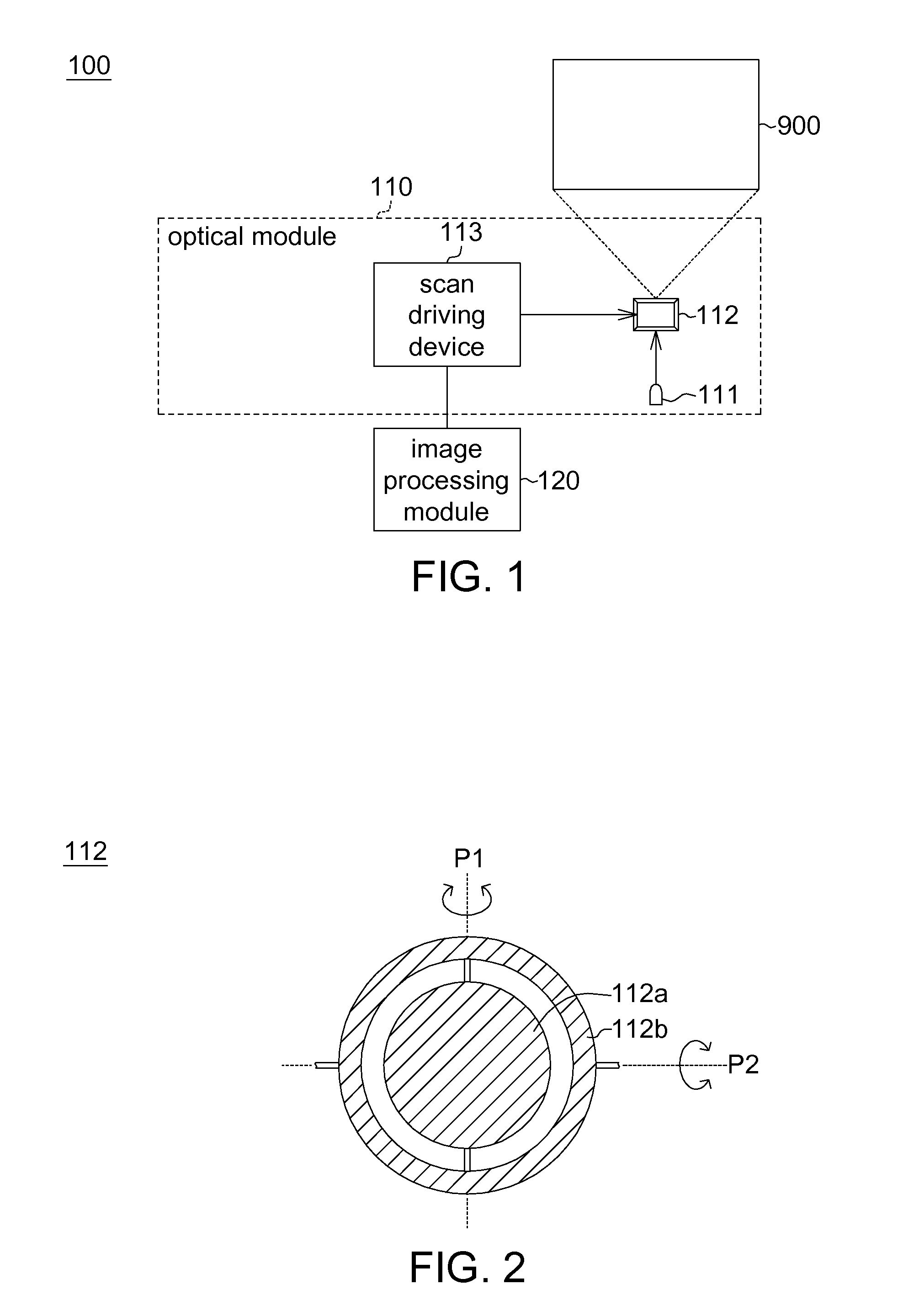
This application claims the benefit of People's Republic of China application Serial No. 201210513569.9, filed Dec. 4, 2012, the subject matter of which is incorporated herein by reference. 1. Field of the Invention The invention relates in general to a projection device and a controlling method, and more particularly to a scan projection device and a scan controlling method. 2. Description of the Related Art Conventional projection technology uses pixel array for projecting an image. Along with the advance in projection technology, a new projection device which projects an image by way of scanning has been provided. The scan projection device uses a micro-electro-mechanical system (MEMS) mirror swinging in two dimensions to drive the image beam to scan a projection surface by way of such as raster scanning or Lissajous scanning, and produces an image through the persistence of vision perceived by human eyes. In general, the MEMS mirror swings in two dimensional directions, such as a horizontal direction and a vertical direction. The swing frequency is defined as the resonance frequency of the MEMS mirror. For example, the horizontal swing frequency is 18 KHz, and the vertical scanning frequency is 60 Hz. Normally, the vertical resonance frequency of the MEMS mirror is about 10 Hz to 1000 Hz. That is, unless the inputted control signal is a precise mono frequency wave such as a 60 Hz sine wave, otherwise all harmonic waves of the vertical control signal whose frequency ranging between 10 Hz to 1000 Hz will make the MEMS mirror generate a corresponding reaction. Consequently, the MEMS mirror will have non-uniform speed in the vertical direction and horizontal bright lines will occur to the projection image. To resolve the above problems, the industries currently suppress the phenomenon of horizontal bright lines by way of feedback control, which requires many additional controlling circuits, not only increasing cost but also decreasing reliability. The invention is directed to a scan projection device and a scan controlling method which eliminates the phenomenon of horizontal bright lines through the design of reverse scan along a scan trace and the design of the scanning frequencies. According to an embodiment of the present invention, a controlling method of a scan projection device. The scan projection device comprises a scanning module. The controlling method of the scan projection device comprises the following steps of: controlling a first direction scanning frequency of the scanning module; controlling a second direction scanning frequency of the scanning module, wherein the first direction scanning frequency is 2N+1 times of the second direction scanning frequency, and N is an integer; and scanning a projection surface back and forth along the scan trace at the first direction scanning frequency and the second direction scanning frequency. According to another embodiment of the present invention, a scan projection device is provided. The scan projection device comprises a light source module, a scanning module and a scan driving device. The light source module is for providing an image beam. The scanning module has a first direction scanning frequency and a second direction scanning frequency. The first direction scanning frequency is 2N+1 times of the second direction scanning frequency, wherein N is an integer. The scanning module is for projecting the image beam towards a particular direction and scanning a projection surface. The scan driving device controls the scanning module to scan the projection surface back and forth along the scan trace at the first direction scanning frequency and the second direction scanning frequency. The above and other aspects of the invention will become better understood with regard to the following detailed description of the preferred but non-limiting embodiment(s). The following description is made with reference to the accompanying drawings. Referring to The light source module 111 is for providing an image beam, which comprises at least a laser light source (not illustrated). The laser light source may emit such as a He—Ne laser light, a CO2laser light or a halogenated inert gas light. The laser light source may provide a mono color laser light or a multi-color laser light such as red, green and blue laser light. The light source module 111 further comprises an optical assembly (not illustrated) for projecting the laser light emitted by the laser light source to the scanning module 112. The scanning module 112 can be a micro-electro-mechanical system (MEMS) mirror. Referring to In the present embodiment, the scanning module 112 drives the image beam to scan in the first direction and the second direction at different swing frequencies. In other words, the first direction scanning frequency is different from the second direction scanning frequency. As indicated in The image processing module 120 is for controlling the optical module 110 according to an image signal. The scan driving device 113 and the image processing module 120 are such as a chip, a firmware circuit or a storage medium storing several programming codes. The scan projection device 100 of the present embodiment eliminates the phenomenon of horizontal bright lines through the design of reverse scan along a scan trace and the design of the scanning frequencies. The controlling method of the scan projection device 100 of the present embodiment is exemplified by a flowchart below. Referring to For exemplary purpose, let the display format be the 480P video display format, the first direction be the horizontal direction, the vertical resolution of the progressive scanning be 480, and the horizontal scanning frequency f1 be 18 KHz. In the present embodiment, the first direction scanning frequency f1 is a sine wave frequency, and the first direction scanning frequency f1 is a fixed mono frequency. In step S102, the scan driving device 113 controls a second direction scanning frequency f2 of the scanning module 112, wherein the first direction scanning frequency f1 is 2N+1 times of the second direction scanning frequency f2, and N is an integer. Let the display format be the 480P video display format, the first direction be the horizontal direction, and the second direction be the vertical direction. When the horizontal scanning frequency f1 is such as 18 KHz and N is such as 10, the vertical scanning frequency f2 is such as 857 Hz. Also, when the horizontal scanning frequency f1 is such as 18 KHz and N is such as 250, the vertical scanning frequency f2 is such as 36 Hz. In the present embodiment, the second direction scanning frequency f2 is a sine wave frequency, and the second direction scanning frequency f2 is a fixed mono frequency. In step S103, the scan driving device 113 drives an image beam of the scanning module 112 to scan the projection surface 900 back and forth along a scan trace at the first direction scanning frequency f1 and the second direction scanning frequency f2. Referring to Referring to The above scanning process is controlled by a mono frequency signal rather than a large area total harmonic signal, hence eliminating the phenomenon of horizontal bright lines. Moreover, the method of the invention can eliminate the phenomenon of horizontal bright lines without adding any feedback control circuits, hence avoiding the increase in cost and the decrease in reliability. As indicated in As indicated in As disclosed above, the scan projection device 100 and the controlling method of the present embodiment can eliminate the phenomenon of horizontal bright lines through the design of reverse scan along a scan trace and the design of the scanning frequencies without adding any feedback control circuits, hence avoiding the increase in cost and the decrease in reliability. While the invention has been described by way of example and in terms of the preferred embodiment(s), it is to be understood that the invention is not limited thereto. On the contrary, it is intended to cover various modifications and similar arrangements and procedures, and the scope of the appended claims therefore should be accorded the broadest interpretation so as to encompass all such modifications and similar arrangements and procedures. A scan projection device and a controlling method are projected. The scan projection device comprises a light source module, a scanning module and a scan driving device. The light source module is for providing an image beam. The scanning module has a first direction scanning frequency and a second direction scanning frequency. The first direction scanning frequency is 2N+1 times of the second direction scanning frequency, wherein N is an integer. The scanning module is for projecting the image beam towards a particular direction and scanning a projection surface. The scan driving device controls the scanning module to scan the projection surface back and forth along a scan trace at the first direction scanning frequency and the second direction scanning frequency. 1. A controlling method of a scan projection device, wherein the scanning projector device comprises a scanning module, and the controlling method comprises:
controlling a first direction scanning frequency of the scanning module; controlling a second direction scanning frequency of the scanning module, wherein the first direction scanning frequency is 2N+1 times of the second direction scanning frequency, and N is an integer; and scanning a projection surface back and forth along a scan trace at the first direction scanning frequency and the second direction scanning frequency. 2. The controlling method according to 3. The controlling method according to 4. The controlling method of according to 5. The controlling method of according to 6. The controlling method of according to 7. A scan projection device, comprising
a light source module for providing an image beam; a scanning module having a first direction scanning frequency and a second direction scanning frequency, wherein the second direction scanning frequency is 2N+1 times of the first direction scanning frequency, N is an integer, and the scanning module is for projecting the image beam towards a particular direction and scanning on a projection surface; and a scan driving device for controlling the scanning module to scan the projection surface back and forth along a scan trace at the first direction scanning frequency and the second direction scanning frequency. 8. The scan projection device according to 9. The scan projection device according to 10. The scan projection device according to BACKGROUND OF THE INVENTION
SUMMARY OF THE INVENTION
BRIEF DESCRIPTION OF THE DRAWINGS
DETAILED DESCRIPTION OF THE INVENTION