Pump, In Particular Pneumatic Pump
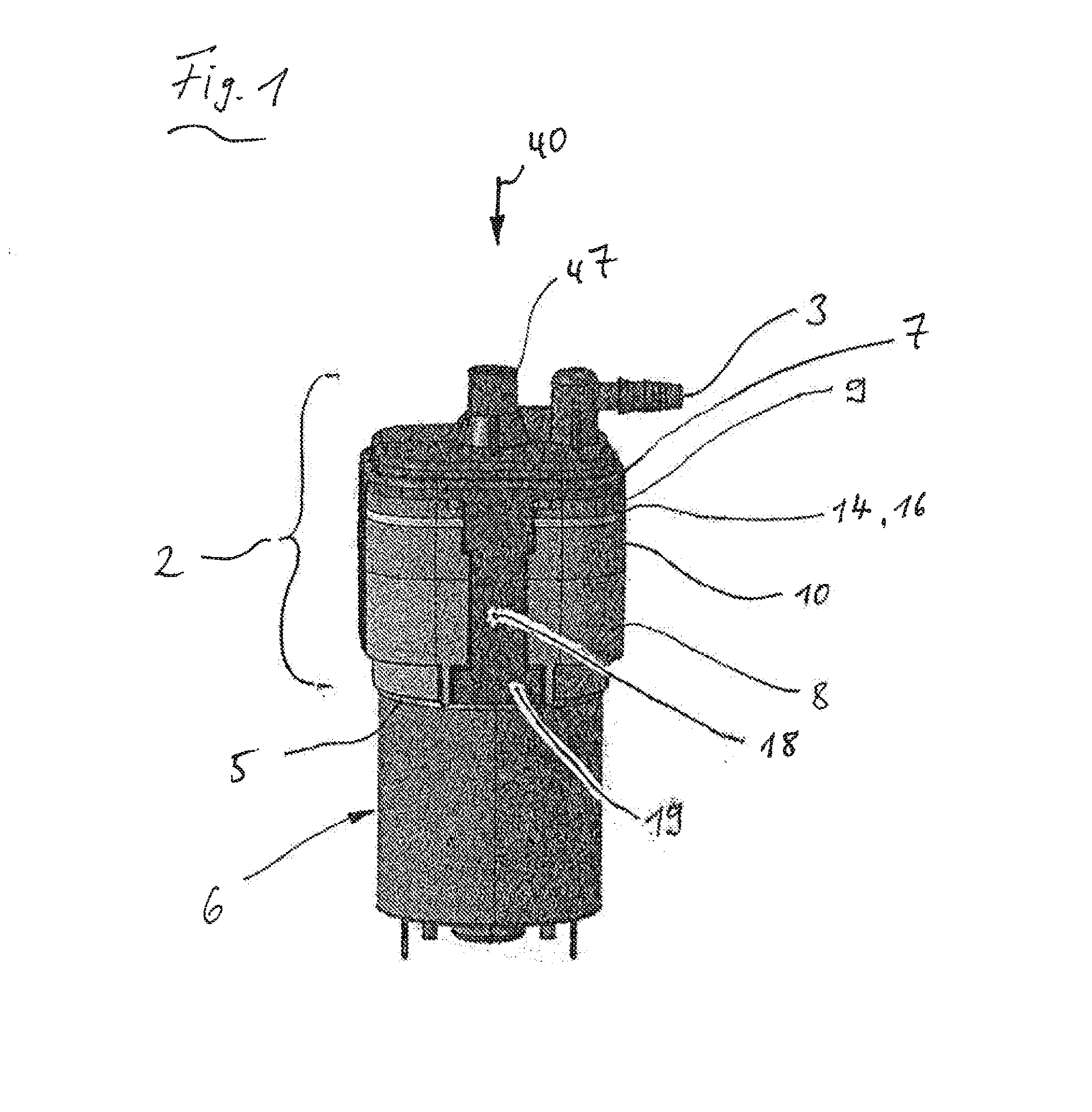
The invention refers to a pump, in particular to a pneumatic pump. Pneumatic pumps are used in the automotive sector, for example, for filling the seat bladders with air to change the contour of the seat's sitting and backrest areas. A pump used for the purpose named above, for example, has at least one pump chamber. By enlarging and reducing the chamber volume with the help of a drive unit, surrounding air is suctioned into the pump chamber during volume enlargement and air is driven out from the pump chamber during volume reduction. To control the corresponding air flows, the pump is equipped with an inlet valve that has a valve element for controlling the inlet opening. The inlet valve opens autonomously when the pump chamber enlarges and air flows into it from the surroundings. An outlet valve serves for controlling the outgoing airflow. It is likewise equipped with a valve element, but it controls an outlet opening which opens when air is driven out of the pump chamber. A pump of the type described above is additionally equipped with a pressure relief valve used especially when a vehicle's seat bladders are being filled because they can leak under an excess pressure load. The pressure relief valve, in turn, has a valve element that closes a pressure relief opening and in closing direction rests on a spring element arranged in a spring space. When the pressure in the pump chamber exceeds a preset limit value, the excess pressure valve opens when there is a limit pressure set by the spring element. With regard to the respectively permissible maximum pressure of the pneumatic system or of a designed part thereof, the limit pressure can vary depending on the application. So far, the approach has been to use springs of various strengths in the assembly of the pump, but this entails a corresponding logistical and technical assembly effort. Additionally, there is the risk of that the wrong springs could be fit into the pump during assembly. The task of the invention is to suggest a pump of the type described above to remedy this situation. This task is solved according to claim 1 by arranging a stop element accessible from the external side of the housing and movable in closing direction on which the spring element can rest with its end pointing towards the closing direction. In this way, the required limit pressure can be easily adjusted during assembly by building in a spring element in the spring space that can be universally used for limiting the pressure range. Afterwards, the stop element is brought into the spring space and—while a pressure corresponding to the limit pressure is applied on the pump—is positioned with regard to its distance to the valve element in such a way that the desired limit pressure is reached. When doing so, deviations from limit pressure resulting from manufacturing tolerances can be compensated. In an especially preferred design variant (particularly advantageous in pump housings made of plastic) it is foreseen for the inner wall of the spring space to have a regulating area extending along the closing direction by holding the excessively dimensioned stop element in a clamped way with regard to the regulating area, whereby the spring space has an actuating opening through which the stop element advancing in closing direction is accessible with a tappet or the like, for example. In this case, the clamping force can be chosen through corresponding dimensional ratios in such a way that the stop element impinged on by the spring element against the closing direction is reliably held in the intended position in the adjustment area. Depending on the chosen excess of the stop element, a more or less elastic and/or plastic deformation of the stop element takes place and/or of a housing wall that circumscribes the spring space. Particularly in the case of housings made of soft materials such as plastic, a stop element made of a material harder than the one used for the pump's housing or for the housing wall that circumscribes the spring space is advantageous. Here, the stop element is pressed into the material of a housing wall that circumscribes the spring space. A metallic stop element is preferably used. Seen in top view in closing direction, the stop element has a complementary shape to the inner transversal shape of the adjustment area. One result of this is the accomplishment of a sealing of the spring space towards the surroundings and another result is a higher clamping effect. Penetration of humidity into the spring space, for example, is thereby prevented. Preferably, a stop element executed as a sphere is used, in which case the adjustment area that acts together with the stop element is circularly cylindrical, i.e. forms the surface shell of a circular cylinder. This design rules out a wrong assembly caused by erroneously positioning the stop element in the spring space, for example in a wrong turning position with regard to an axis running parallel to the closing direction. When pressure relief valves of the type used here open, this is accompanied most of the time by the generation of noise. In at least one design variant independent from the spring space and stop element designs, noise reduction is achieved by having the lower-pressure side of the pressure relief valve end in the spring space. With regard to its surroundings, the spring space can be fully closed so there is no fluid connection to the atmosphere and therefore the propagation of an airborne noise generated inside the spring space is prevented from reaching the exterior. Even if the spring space is connected to the surroundings through a bore hole to allow pressure to equalize between spring space and surroundings—as is the case in a design variant—if excess pressure occurs, this bore hole can have a very small flow cross-section. It is different with the inlet opening, whose flow cross-section cannot be reduced at will so that an airborne noise generated in the pressure relief valve can propagate almost unhindered into the surroundings. The pressure-equalizing bore hole that connects the spring space to the surroundings mentioned above can be done completely without if the spring space is connected to the inlet opening, in which case its end located upstream (i.e. its entrance opening) does not end directly in the surroundings but in a housing space of the pump in which one drive unit for actuating the pump is arranged. In doing so, the drive unit acts like the insulating material in a sound absorber to eliminate the noise. However, in conventional pumps of the type presented here, the inlet opening is separated by a duct wall of the other housing spaces. The invention will now be explained in more detail with the help of the enclosed drawings, which show: To explain the invention, exemplary reference is made to a pneumatic pump, in which case the designs described also apply to pumps for fluids. The pump 1 shown in the illustrations is intended to be installed in a vehicle seat and serves for filling seat bladders to change the contour of a vehicle seat in the sitting or backrest area, for example. The pump 1 comprises a housing 2 (especially made of plastic) on which an outlet connection piece 3 has been form-fitted. The side of the housing 2 supporting the outlet connection piece 3 will also be referred to as upper side 4 below. A motor 6, especially an electric motor, has been flanged onto the lower side 5 of the housing 2. The housing 2 comprises an upper part 7 and a lower part 8, in which case the upper part 7 supports the connection piece 3 and forms the upper side 4. Two plate-shaped supports—namely an upper support 9 and a lower support 10—are clamped sandwich-like between the upper part 7 and the lower part 8. Between the upper support 9 and the upper part of the housing 7, a plate-shaped valve membrane 13 made of an elastic material (e.g. a rubbery polymer) has been clamped in. Four pot-shaped depressions that create pump chambers 15 have been form-fitted in the pump membrane. In its upper border, the pump membrane 14 has a circumferential bulge 16 clamped between the upper support 9 and the lower support 10. On the upper part of the housing, peripheral arms 18 extending downwards have been form-fitted along the middle longitudinal axis 17 of the pump. On the free end of two diametrically opposing arms 18, a rear grip element 18 has been fixed or form-fitted that, by creating an axially effective positive-locking fit, grips an opposing element 20 on the lower part of the housing 8 from behind. As a result of this, the valve membrane 13, the upper support 9, the pump membrane 14 and the lower support 10 are axially tensed between the upper part of the housing 7 and the lower part of the housing 8. In the lower part of the housing 9, there is a turnstile 23 obliquely positioned with respect to the middle longitudinal axis 17 that has been mounted on an eccentric 25 with an axis 24 protruding from its underside. The eccentric 25, in turn, is connected in a fixed rotary way to a drive shaft 26 of the motor 6. The pump membrane 14 has on the underside, in the area of the pump chambers 15, a tappet-shaped extension 27 with a head-shaped end 28 fixed in a recess 29 of the turnstile. Each pump chamber 15 is assigned to an inlet valve 30 and an outlet valve 33. The outlet valves 33 are arranged in an outlet port 34 that extends inwards from the pump chamber 15 all the way to the inlet connection piece 3 and finally ends in the surroundings. The inlet valves 30 are arranged in an inlet port 35 in which—with respect to the inflow direction 36—suctioned air flows towards the pump chamber, the end 37 located upstream ends in a housing space 38, in which a drive unit 39 for actuating the pump chambers 15 (i.e. for enlarging and reducing them), in this case the turnstile 23 and the eccentric 25, are arranged. The inlet valves 30 and the outlet valves 33 have in each case a valve element 30 On the upper side of the valve membrane 13, all inlet ports 35 end in a collecting space 41 (located above the valve membrane 13) arranged centrally on the pump in the direction of the arrow 40 in Apart from the inlet and outlet vales 30, 33, the pump 1 is equipped with a pressure relief valve 43 developed between a central area of the valve membrane 13 that forms a valve element 43 A largely cylindrical connection piece 47 open towards the upper side of the housing 4 juts out from a central position of the upper part of the housing 7. The interior of the connection piece creates a spring space 49 for receiving a spring element 48, namely a threaded compression spring. On its front side facing away from the upper part of the housing 7, the connection piece 47 has an assembly opening 50 over which the spring element 48 can be inserted into the spring space 49. The spring element 49 supports itself with its lower end on the valve element 43 In the design variant shown in The way the pump works will now be explained: When the air from the surroundings or from the housing space 38 is suctioned, it enlarges the pump chambers 15 by moving the extensions 27 of the pump membrane 14 downwards. The air through the openings 46, 42 If the extensions 27 move upwards, the pump chambers 15 are made smaller and air is driven out of Them. The air that was driven out flows through the outlet openings 33 If excess pressure exceeds the limit pressure, the pressure relief valve 43 reacts. When this occurs, the valve element 43 The invention relates to a pump comprising a housing (2), comprising at least one pump chamber (15), comprising an inlet valve (30) that has a valve element (30a) which controls an inlet opening (30c), comprising an outlet valve (33) that has a valve element (33a) which controls an outlet opening (33c), comprising a pressure relief valve (43) that has a valve element (43a) which controls a pressure relief opening (43c) and on which a spring element (48) acts in the closing direction (31), and comprising a spring chamber (49) that receives the spring element. A stop element (51) which can be accessed from the housing outer face and which can be adjusted in the closing direction (31) is arranged in the spring chamber (49), the spring element (48) end that faces away from the closing direction resting against the stop element. 1. Pump with a housing (2), with at least one pump chamber (15), with an inlet valve (30) equipped with a valve element (30 2. Pump according to 3. Pump according to 4. Pump according to 5. Pump according to 6. Pump according to 7. Pump according to 8. (canceled) 9. Pump according to 10. (canceled) 11. Pump according to 12. Pump according to 13. Pump according to 14. Pump according to 15. Pump according to 16. Pump according to