UTILITY POWER-LINE-JUMPER APPARATUS WITH EXTERNAL VENTING
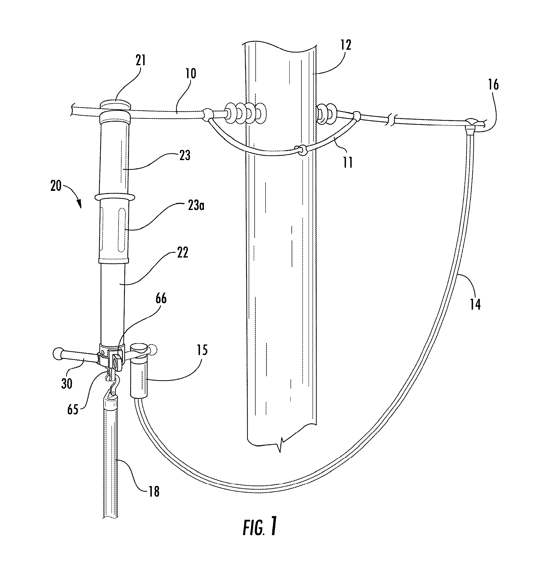
This U.S. non-provisional patent application is a continuation of, incorporates entirely by reference, and claims the benefit of priority to Ser. No. 13/628,415 filed on Sep. 27, 2012, for a Utility Power Line Jumper Apparatus with External Venting, which has issued as U.S. Pat. No. 8,759,672. This U.S. non-provisional also incorporates entirely by reference and claims the benefit of priority to U.S. Patent Application Ser. No. 61/540,533 for a Utility Power Line Jumper Apparatus with External Venting (filed Sep. 28, 2011), which is hereby incorporated by reference in its entirety. The present invention relates to the field of jumper equipment for the electric utility industry. Power is primarily distributed to residential and commercial locations using overhead-power-line networks. These overhead-power-line networks require regular maintenance and repair to ensure proper operation. This maintenance and repair work on overhead power lines can be quite dangerous. For example, cutting live power cables can result in dangerous electric arcing. Conventionally, an upstream switch must be opened before cutting any downstream portion of overhead power lines so that repairs or maintenance can be performed. Alternatively, devices have been developed for breaking and returning the load to overhead power lines without the need to open the upstream switch. An exemplary load-breaking and load-returning apparatus is disclosed in commonly assigned U.S. Pat. No. 6,078,008, which is hereby incorporated by reference in its entirety. That said, a need exists for an improved load-breaking and load-returning apparatus. In one aspect, the present invention embraces a line-jumper apparatus. The line-jumper apparatus typically includes a first connector, a second connector, and a housing attached to the first connector and the second connector. In a closed position, the housing provides a low-resistance current path and a high-resistance current path between the first connector and the second connector. In an open position, the housing inhibits current from flowing between the first connector and the second connector. The housing is configured so that, when the housing is transitioned from the closed position to the open position, the low-resistance current path is opened before the high-resistance current path. The housing typically includes a safety mechanism that prevents the low-resistance current path from being opened unless the high-resistance current path is closed. In a particular embodiment, the housing includes an outer housing, an inner housing, an intermediate assembly movably positioned within the housing, a retractable contact assembly movably positioned within the housing, and a safety key in communication with the intermediate assembly and the retractable contact assembly. When the housing is in the closed position, the low-resistance current path typically extends from the first connector to the inner housing, the inner housing to the intermediate assembly, and the intermediate assembly to the second connector. Furthermore, when the housing is in the closed position, the high-resistance current path extends from the first connector to the inner housing, the inner housing to the retractable contact assembly, the retractable contact assembly to the intermediate assembly, and the intermediate assembly to the second connector. The intermediate assembly typically includes an engaging assembly (e.g., a toggle assembly or a key assembly), a nonconductive portion, and a venting structure having vents. The retractable contact assembly is typically engageable by the engaging assembly (e.g., with a toggle or a key). The housing is typically configured so that, when the engaging assembly is engaged with the retractable contact assembly, the intermediate assembly remains in electrical communication with the retractable contact assembly in a way that the high-resistance current path remains closed. The safety key is typically configured to prevent the intermediate assembly from moving within the housing in a way that would allow the low-resistance current path to open unless the engaging assembly is engaged with the retractable contact assembly. When the housing is transitioned from the closed position to the open position, the engaging assembly typically engages then releases the retractable contact assembly. The engaging assembly typically releases the retractable contact assembly after the low-resistance current path has opened. Upon being released by the engaging assembly, the retractable contact assembly typically automatically retracts within the housing so that the intermediate assembly is not in electrical communication with a conductive portion of the retractable contact assembly. In another embodiment, the line-jumper apparatus typically includes a first connector, a second connector, and a housing attached to the first connector and the second connector. The housing typically defines a primary axis between the first connector and the second connector. In a closed position, the housing provides a low-resistance current path and a high resistance current path between the first connector and the second connector. In an open position, the housing inhibits current from flowing between the first connector and the second connector. The housing is configured is that, when the housing is transitioned from the closed position to the open position, the low-resistance current path is opened before the high resistance current path. The housing typically includes a venting structure having vents for allowing gases to escape the housing. When the housing is in the open position, the vents are configured to (i) extend out of the housing and (ii) release hot gases that occur during electric arcing primarily in one or more directions substantially perpendicular to the primary axis. In yet another embodiment, the line-jumper apparatus typically includes a first connector, a second connector, and a housing attached to the first connector and the second connector. The second connector typically defines a cavity therethrough and includes an internal pin connector that protrudes into the cavity. In a closed position, the housing provides a low-resistance current path and a high resistance current path between the first connector and the second connector. In an open position, the housing inhibits current from flowing between the first connector and the second connector. The housing is configured is that, when the housing is transitioned from the closed position to the open position, the low-resistance current path is opened before the high resistance current path. The housing typically includes a venting structure configured to (i) slidably engage the second connector's cavity and (ii) at least partially extend out of the second connector when the housing is in the open position. The venting structure typically includes (i) vents for allowing gases to escape the housing in the open position and (ii) a guide rail. The internal pin connector, when the housing is transitioned from the closed position to the open position, is configured to slidably engage the guide rail to (i) prevent the rotation of the venting structure and (ii) maintain an electrical connection between the housing and the second connector. The foregoing illustrative summary, as well as other exemplary objectives and/or advantages of the invention, and the manner in which the same are accomplished, are further explained within the following detailed description and its accompanying drawings. In one aspect, the present invention embraces a portable apparatus for breaking and returning a load to a portion of a power line. In this regard, The line-jumper apparatus 20 typically includes a lower outer housing 22 and an upper outer housing 23. The upper outer housing 23 typically includes a handle 23 The line-jumper apparatus 20 typically includes an engaging ring 65 and a reset trigger 66, which enable the line-jumper apparatus 20 to be transitioned between a closed position and an open position. As depicted in To facilitate the transition between the closed position and the open position, the line-jumper apparatus 20 typically includes a low-resistance current path and a high-resistance current path. In the closed position, both the low-resistance current path and the high-resistance current path are typically closed, whereas, in the open position, both the low-resistance current path and the high-resistance current path are open. During the transition between the closed position and the open position, the low-resistance current path will typically open before the high-resistance current path. As depicted in The line-jumper apparatus 20 typically includes an intermediate assembly 40 that is movably positioned within the outer housing (e.g., the lower outer housing 22 and the upper outer housing 23). At least a portion of the intermediate assembly 40 is also typically movably positioned within the inner housing 25. The intermediate assembly 40 typically includes a toggle assembly 45 (e.g., an engaging assembly) that is connected to an insulating portion 46 (i.e., a nonconductive portion). The toggle assembly 45 includes a key 34 and a toggle 37. A plug 47 typically surrounds an extended portion 45 An interior contact 49 is typically positioned within the insulating portion 46. At least a portion of the interior contact 49 typically protrudes from the lower portion of the insulating portion 46 and is in contact with the venting structure 55. An intermediate contact 50 connects the insulating portion 46 to the venting structure 55 (e.g., via threads). The intermediate contact 50 and the interior contact 49 are formed from one or more conductive materials. As depicted in The second connector 30 surrounds a portion of the venting structure 55 (e.g., by defining a cavity) and is typically connected to the bottom of the lower outer housing 22. The second connector 30 typically includes one or more bottom contact rings 29. The bottom contact rings 29 are typically formed from one or more canted coil springs. The second connector 30 also typically includes a pin 64 (e.g., a pin contact) that is slidably engaged with the guide rail 62. A spring 64 Finally, the second connector 30 typically includes two conductor bars 30 Because the inner-housing contact rings 28 and the bottom contact rings 29 are typically formed from canted coil springs, the inner-housing contact rings 28 and the bottom contact rings 29 typically have low surface friction. Therefore, the reset spring 63 can have a relatively low spring constant (i.e., spring rate). In this regard, the reset spring 63 typically has a spring constant of less than about 1.0 pound per inch of compression, more typically less than about 0.65 pound per inch of compression. The reset trigger 66 is typically connected to the second connector 30. When the line-jumper apparatus 20 is in the open position, the reset trigger 66 engages the locking structure 61 to lock the line-jumper apparatus 20 into the open position. When the reset trigger 66 is disengaged, the line-jumper apparatus 20 can be returned (e.g., automatically returned) to the closed position. In this regard and as depicted in As depicted in As noted above, in the closed position, the line-jumper apparatus 20 provides a closed low-resistance current path from the first connector 21 to the second connector 30. In this regard, the low-resistance current path typically flows from the first connector 21 through the inner housing 25 to the inner-housing contact rings 28, from the inner-housing contact rings 28 to the intermediate contact 50, from the intermediate contact 50 through the venting structure 55 to the bottom contact 67, and, finally, from the bottom contact 67 through the bottom contact rings 29 to the second connector 30. During the transition from the closed position to the open position, the low-resistance current path is typically broken once the intermediate contact 50 no longer forms an electrical connection with the inner-housing contact rings 28. As the line-jumper apparatus 20 is transitioned from the closed position to the open position, the intermediate contact 50 moves downward relative to the inner-housing contact rings 28. Once the intermediate contact 50 has moved sufficiently so as to no longer form an electrical connection with the inner-housing contact rings 28 (e.g., as depicted in To provide a high-resistance current path, the line-jumper apparatus 20 typically includes a retractable contact assembly 35. As depicted in FIGS. 7 and 10-13, the retractable contact assembly 35 typically includes a fixture 36, an assembly rod 38, an assembly contact 39, and an assembly plug 41. As depicted in As depicted in The springs 31 In the closed position, the line-jumper apparatus 20 provides a closed high-resistance current path from the first connector 21 to the second connector 30. In this regard, the high-resistance current path typically flows from the first connector 21 through the inner housing 25 to the springs 31 During the transition from the closed position to the open position, and immediately before the trigger plug 73 engages the locking structure 61 to lock the line-jumper apparatus 20 into the open position, the top portion of the toggle 37 typically comes into contact with a sleeve 42 that is positioned within the inner housing 25. Contact with the sleeve 42 causes the toggle 37 to unseat from the fixture recess 36 The present line-jumper apparatus 20 typically includes a safety mechanism that prevents the low-resistance current path from being broken (e.g., opened) unless the high-resistance current path is closed. To provide this safety mechanism, the toggle assembly 45 typically includes the key 34. If the toggle 37 is not in a position allowing it to engage the fixture recess 36 This safety feature is depicted in more detail in As depicted in In an alternative embodiment, the toggle may be eliminated. In this regard, As depicted in During the transition from the closed position to the open position, and immediately before the trigger plug 73 engages the locking structure 61 to lock the line-jumper apparatus 20 into the open position, the protruding portion of the key 34 typically comes into contact with a sleeve 42 that is positioned within the inner housing 25. Contact with the sleeve 42 causes the key 34 to sufficiently depress so that the key opening 34 In the specification and/or figures, typical embodiments of the invention have been disclosed. The present invention is not limited to such exemplary embodiments. The use of the term “and/or” includes any and all combinations of one or more of the associated listed items. The figures are schematic representations and so are not necessarily drawn to scale. Unless otherwise noted, specific terms have been used in a generic and descriptive sense and not for purposes of limitation. A line-jumper apparatus typically includes a first connector, a second connector, and a housing attached to the first connector and the second connector. In a closed position, the housing provides a low-resistance current path and a high-resistance current path between the first connector and the second connector. In an open position, the housing inhibits current from flowing between the first connector and the second connector. The housing is configured so that, when the housing is transitioned from the closed position to the open position, the low-resistance current path is opened before the high-resistance current path. The housing typically includes a safety mechanism that prevents the low-resistance current path from being opened unless the high-resistance current path is closed. 1. A line-jumper apparatus, comprising:
a first connector; a second connector; and a housing attached to said first connector and said second connector, said housing being capable of transitioned between a closed position and an open position, said housing in the closed position providing a low-resistance current path and a high-resistance current path between said first connector and said second connector, said housing in the open position inhibiting current from flowing between said first connector and said second connector, and said housing being configured so that, when said housing is transitioned from the closed position to the open position, said low-resistance current path is opened before said high-resistance current path is opened; wherein said housing comprises a safety mechanism, said safety mechanism preventing said low-resistance current path from being opened unless said high-resistance current path is closed. 2. A line-jumper apparatus according to 3. A line-jumper apparatus according to 4. A line-jumper apparatus according to 5. A line-jumper apparatus according to 6. A line-jumper apparatus according to an outer housing; an inner housing positioned within said outer housing; an intermediate assembly movably positioned within said housing, a portion of said intermediate assembly extending out of said housing when said housing is in the open position; and a retractable contact assembly movably positioned within said housing and within at least a portion of said intermediate assembly. 7. A line-jumper apparatus according to when said housing is in the closed position, said low-resistance current path extends from said first connector to said inner housing, said inner housing to said intermediate assembly, and said intermediate assembly to said second connector; when said housing is in the closed position, said high-resistance current path extends from said first connector to said inner housing, said inner housing to said retractable contact assembly, said retractable contact assembly to said intermediate assembly, and said intermediate assembly to said second connector; when said housing is in the open position, said inner housing is not in electrical communication with a conductive portion of said intermediate assembly, thereby opening said low-resistance current path; and when said housing is in the open position, said intermediate assembly is not in electrical communication with a conductive portion of said retractable contact assembly, thereby opening said high-resistance current path. 8. A line-jumper apparatus according to said intermediate assembly comprises an engaging assembly for engaging said retractable contact assembly; and when said engaging assembly is engaged with said retractable contact assembly, said intermediate assembly remains in electrical communication with said retractable contact assembly in a way that said high-resistance current path remains closed. 9. A line-jumper apparatus according to when said housing is transitioned from the closed position to the open position, said engaging assembly engages then releases said retractable contact assembly, said engaging assembly releasing said retractable contact assembly after said low-resistance current path has opened by said inner housing not being in electrical communication with a conductive portion of said intermediate assembly; said retractable contact assembly is configured to automatically move within said housing, upon being released by said engaging assembly, so that said intermediate assembly is not in electrical communication with a conductive portion of said retractable contact assembly. 10. A line-jumper apparatus according to 11. A line-jumper apparatus according to 12. A line-jumper apparatus according to 13. A line-jumper apparatus according to 14. A line-jumper apparatus according to 15. A line-jumper apparatus, comprising:
a first connector; a second connector; and a housing attached to said first connector and said second connector, said housing being capable of transitioning between a closed position and an open position, said housing comprising:
an outer housing; an inner housing; an intermediate assembly movably positioned within said housing, said intermediate assembly comprising (i) an engaging assembly, (ii) a nonconductive portion, and (iii) a venting structure having vents; a retractable contact assembly movably positioned within said housing and within at least a portion of said intermediate assembly, said retractable contact assembly being engageable by said engaging assembly; and a safety key in communication with said intermediate assembly and said retractable contact assembly; wherein, when said housing is in the closed position, a low-resistance current path extends from said first connector to said inner housing, said inner housing to said intermediate assembly, and said intermediate assembly to said second connector; wherein, when said housing is in the closed position, a high-resistance current path extends from said first connector to said inner housing, said inner housing to said retractable contact assembly, said retractable contact assembly to said intermediate assembly, and said intermediate assembly to said second connector; wherein, when said housing is in the open position, said low-resistance current path and said high-resistance current path are open, thereby inhibiting current from flowing between said first connector and said second connector; wherein said housing is configured so that, when said engaging assembly is engaged with said retractable contact assembly, said intermediate assembly remains in electrical communication with said retractable contact assembly in a way that said high-resistance current path remains closed; wherein, when said housing is transitioned from the closed position to the open position, said engaging assembly engages then releases said retractable contact assembly, said engaging assembly releasing said retractable contact assembly after said low-resistance current path has opened, said retractable contact assembly, upon being released by said engaging assembly, automatically retracting within said housing so that said intermediate assembly is not in electrical communication with a conductive portion of said retractable contact assembly; and wherein said safety key is configured to prevent said intermediate assembly from moving within said housing in a way that would allow said low-resistance current path to open unless said engaging assembly is engaged with said retractable contact assembly. 16. A line-jumper apparatus according to an open-position locking structure; and a reset trigger, said reset trigger being configured, when said housing is transitioned from the closed position to the open position, to automatically engage said open-position locking structure to lock said housing in the open position after said engaging assembly has released said retractable contact assembly; wherein, when said housing is in the open position, engaging said reset trigger disengages said open-position locking structure. 17. A line-jumper apparatus according to 18. A line-jumper apparatus according to 19. A line-jumper apparatus according to said safety key is connected to said engaging assembly and is configured to engage said retractable contact assembly; when said housing is transitioned from the closed position to the open position, said safety key engages then releases said retractable contact assembly, said safety key releasing said retractable contact assembly after said low-resistance current path has opened, said retractable contact assembly, upon being released by said safety key, automatically retracting within said housing so that said intermediate assembly is not in electrical communication with a conductive portion of said retractable contact assembly; 20. A line-jumper apparatus according to 21. A line-jumper apparatus according to 22. A line-jumper apparatus according to 23. A line-jumper apparatus, comprising:
a first connector; a second connector; and a housing attached to said first connector and said second connector, said housing defining a primary axis between said first connector and said second connector, said housing being capable of transitioning between a closed position and an open position, said housing in the closed position providing a low-resistance current path and a high-resistance current path between said first connector and said second connector, said housing in the open position inhibiting current from flowing between said first connector and said second connector, and said housing being configured so that, when said housing is transitioned from the closed position to the open position, said low-resistance current path is opened before said high-resistance current path is opened; wherein said housing comprises a venting structure having vents for allowing gases to escape said housing; wherein, when said housing is in the open position, said vents are configured to (i) extend out of said housing and (ii) release hot gases that occur during electric arcing primarily in one or more directions substantially perpendicular to said primary axis. 24. A line-jumper apparatus, comprising:
a first connector; a second connector defining a cavity therethrough, said second connector comprising an internal pin connector that protrudes into said cavity; and a housing attached to said first connector and said second connector, said housing being capable of transitioning between a closed position and an open position, said housing in the closed position providing a low-resistance current path and a high-resistance current path between said first connector and said second connector, said housing in the open position inhibiting current from flowing between said first connector and said second connector, and said housing being configured so that, when said housing is transitioned from the closed position to the open position, said low-resistance current path is opened before said high-resistance current path is opened; wherein said housing comprises a venting structure configured to (i) slidably engage said second connector's cavity and (ii) at least partially extend out of said second connector when said housing is in the open position, said venting structure comprising (i) vents for allowing gases to escape said housing in the open position and (ii) a guide rail; wherein said internal pin connector, when said housing is transitioned from the closed position to the open position, is configured to slidably engage said guide rail to (i) prevent the rotation of said venting structure and (ii) maintain an electrical connection between said housing and said second connector. 25. A line-jumper apparatus according to an open-position locking structure; and a reset trigger, said reset trigger being configured, when said housing is transitioned from the closed position to the open position, to automatically engage said open-position locking structure to lock said housing in the open position after said high-resistance current path has opened; wherein said housing comprises a reset spring positioned around said venting structure for automatically returning said housing to the closed position after said reset trigger disengages said open-position locking structure. 26. A line-jumper apparatus according to 27. A line-jumper apparatus according to 28. A line-jumper apparatus according to CROSS-REFERENCE TO PRIORITY APPLICATION
FIELD OF INVENTION
BACKGROUND
SUMMARY
BRIEF DESCRIPTION OF THE DRAWINGS
DETAILED DESCRIPTION