MANUFACTURING METHOD AND APPARATUS FOR FRP BAR USING ROTATIONAL NOZZLE, AND NOZZLE FOR SUCH APPARATUS
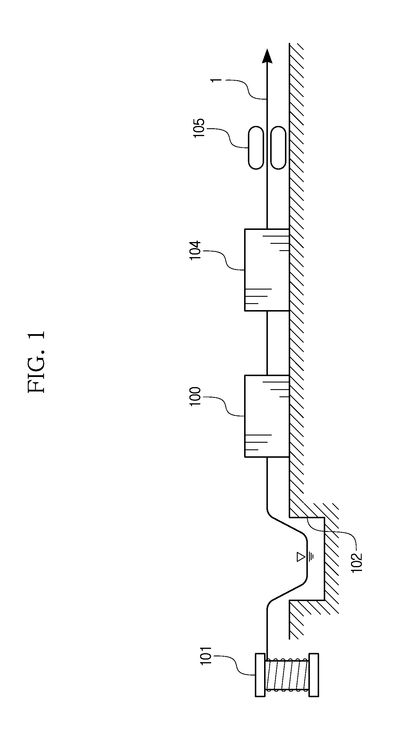
This application claims priority to Korean Patent Application No. 10-2013-0109665, filed on Sep. 12, 2013, and all the benefits accruing therefrom under 35 U.S.C. §119, the contents of which in its entirety are herein incorporated by reference. 1. Field The present invention relates to a manufacturing method and an apparatus for a fiber reinforced polymer (FRP) bar, and more particularly, to a manufacturing method and an apparatus for a FRP bar which does not cause excessive bending deflection even though a fiber having a low elastic modulus is used, by introducing a compression force in advance. In addition, the present invention relates to a method and an apparatus for manufacturing a hybrid FRP bar by using at least two kinds of fibers so that the fibers may be easily distributed to specific locations at the section of the manufactured hybrid FRP bar, and a nozzle for such an apparatus. 2. Description of the Related Art A steel bar used for a reinforced concrete structure is always exposed to possibility of corrosion. A steel bar in concrete is highly likely to contact moisture due to cracks or the like, and in particular, the steel bar is corroded due to residual moisture in the concrete, in addition to cracks. When the steel bar is corroded, the volume of the steel bar expands, which results in separation of concrete cover. Therefore, the reinforced concrete structure loses integrity, which is an essential requirement of the reinforced concrete structure, and is not able to serve as a structural member. In order to solve this problem, rod-shaped products manufactured using a fiber reinforced polymer (FRP) have been used instead of steel bars distributed in a concrete structure or to assist the steel bars. Such a rod-shaped product manufactured using FRP is generally called “FRP bar” or “FRP re-bar” since it is used for reinforcing a concrete structure. Korean Patent Registration No. 10-0702629 and Korean Unexamined Patent Publication No. 10-1987-3861 disclose a technique for manufacturing such a FRP bar. In the prior art, a FRP bar is manufactured by a manufacturing apparatus including a fiber winding reel, a resin supplier, a nozzle, a heater and a drawer. In order to manufacture the FRP bar, first, fibers as thin as threads, supplied from the fiber winding reel, are bound into a bundle and drawn to the drawer. In this time, while passing through the resin supplier, the fibers are formed into a rod shape while entering the nozzle together with a resin, and the resin is hardened through the heater, thereby making the FRP bar. The fibers used for manufacturing a rod-shaped FRP bar having a circular, oval or polygonal section by bundling the fibers impregnated in a resin as described above use carbon fibers, aramid fibers, steel wires, glass fibers or the like, among which glass fibers are advantageous for cost reduction. However, when the FRP bar is manufactured using glass fibers, the glass fibers have a lower elastic modulus than the steel bar even though its tensile strength is much greater than that of the steel bar. Therefore, if the FRP bar is used for reinforcing a bending member, a great drooping is caused at the bending member. In other words, if the FRP bar is manufactured using a fiber having a low elastic modulus such as a glass fiber, an excessive bending deflection is caused at a concrete structure to which a bending load is applied. As a solution, there has been proposed a technique for manufacturing a FRP bar by mixing several kinds of fibers having different elastic modulus. The FRP bar manufactured using several kinds of fibers together may be called a “hybrid FRP bar”. The hybrid FRP bar may ensure good economical feasibility since several kinds of fibers are mixed, thereby ensuring more improved elastic modulus in comparison to a FRP using only glass fibers. The hybrid FRP bar may use, for example, a glass fiber having a low elastic modulus and a carbon fiber having a high elastic modulus. When manufacturing a hybrid FRP bar by using several kinds of fibers, it may be needed to distribute the several kinds of fibers at different locations in the section of the FRP bar. If the hybrid FRP bar uses a glass fiber and a carbon fiber as in the above example, it may be needed to locate the glass fiber at the center of the section and the carbon fiber at the periphery of the section. The fibers used for manufacturing a FRP bar have a very small diameter like threads, and several ten or hundred fibers are bound for use. If there is proposed a technique capable of effectively manufacturing a hybrid FRP bar in a state where several kinds of such fibers are used and also each kind of fiber is distributed at a specific location on the section of the FRP bar as designed, the hybrid FRP bar will be efficiently used suitable for a stress situation or other use conditions. The present invention is directed to providing a FRP bar which does not cause excessive bending deflection even though it is used for a concrete structure to which a bending load is applied. Further, the present invention is directed to providing a manufacturing method for a hybrid FRP bar using at least two kinds of fibers which are distributed at specific locations of the section of the hybrid FRP bar as designed, and a manufacturing apparatus therefor. In addition, the present invention is directed to providing a manufacturing method for a hybrid FRP bar using at least two kinds of fibers so that a fiber distribution pattern in the section of the hybrid FRP bar may be easily changed as designed, and a manufacturing apparatus therefor. In one aspect, the present invention provides a manufacturing apparatus for a rod-shaped fiber reinforced polymer (FRP) bar composed of a fiber and resin, the manufacturing apparatus comprising a fiber winding reel, a resin supplier, a nozzle and a drawer, wherein the nozzle includes a pipe-shaped outer nozzle having a penetration hole formed at its center and a plurality of middle nozzles disposed at an inlet of the outer nozzle and disposed so that one middle nozzle is located inside another middle nozzle; wherein dividing members are disposed at an interval between the middle nozzle and the outer nozzle and an interval between the middle nozzles so that one end of the dividing member is inserted into an insert groove formed in an inner surface of the outer nozzle or an inner surface of the middle nozzle to include an elastic member therein and the other end of the dividing member is located in a hooking groove formed in an outer surface of the middle nozzle opposite thereto, the location of the dividing member being changed by a rotation of the middle nozzle; and wherein a fiber is supplied through a central hole of the middle nozzle located at an innermost side, a fiber is supplied through regions divided in a circumferential direction by the dividing member in the interval of the middle nozzles, and a fiber is supplied through a region divided in a circumferential direction by the dividing member in the interval between the middle nozzle and the outer nozzle, thereby manufacturing a hybrid FRP bar having a section in which the fibers form a greater number of fiber distribution layers from a center of the FRP bar to the outside and are also distinguishably distributed in each fiber distribution layer in a circumferential direction, wherein if the location of the dividing member is changed by a rotation of the middle nozzle, a hybrid FRP bar is manufactured so that locations of a plurality of regions divided in a circumferential direction in each fiber distribution layer are changed. Meanwhile, in other aspect, the present invention provides a manufacturing method for a FRP rod using the FRP rod manufacturing apparatus described above, and a nozzle therefor. In particular, the present invention provides a manufacturing method for a FRP rod using the FRP rod manufacturing apparatus described above, in which a fiber supplied through a central hole of the middle nozzle located at an innermost side, a fiber supplied through the interval of the middle nozzles, and a fiber supplied through the interval between the middle nozzle and the outer nozzle are different from each other, thereby manufacturing a hybrid FRP bar having a section in which different kinds of fibers are distributed in a plurality of fiber distribution layers, respectively. In addition, the present invention provides a manufacturing method for a FRP rod using the FRP rod manufacturing apparatus described above, in which different kinds of fibers are supplied to regions divided in a circumferential direction by the dividing member in the interval between the middle nozzle and the outer nozzle and in the interval of the middle nozzles, thereby manufacturing a hybrid FRP bar having a section in which different kinds of fibers are distributed in a circumferential direction in each fiber distribution layer. The above and other aspects, features and advantages of the disclosed exemplary embodiments will be more apparent from the following detailed description taken in conjunction with the accompanying drawings in which: Hereinafter, an embodiment of the present invention will be described with reference to the accompanying drawings. Even though the present invention is based on the embodiments depicted in the drawings, it is just for better understanding, and the spirit, essential configurations and operations of the present invention are not limited thereto. In the present invention, fibers impregnated in the resin are bundled and drawn to make a fiber reinforced polymer (FRP) bar. For this, similar to the prior art, a manufacturing apparatus for a FRP bar according to the present invention may include a fiber winding reel 101, a resin supplier 102, a nozzle 100 and a drawer 105. In the present invention, a fiber used for manufacturing the FRP bar may be a carbon fiber, an aramid fiber, a glass fiber or the like, and a steel wire such as a piano wire may also be used. Therefore, in the disclosure of this specification, the term “fiber” mentioned as material of the FRP bar should be understood as including a steel wire such as a piano wire in addition to the carbon fiber, the aramid fiber, the glass fiber and other fibers made of synthetic resins or other various materials. In the manufacturing apparatus and the manufacturing method for a FRP bar according to the present invention, the nozzle 100 for bundling fibers impregnated in a resin into a rod shape with a designed sectional size has the following configuration. In detail, As shown in the figures, in the present invention, the nozzle 100 is configured to include a pipe-shaped outer nozzle 11 having a penetration hole formed at its center and having an inlet with a greater sectional area than an outlet, and a plurality of middle nozzles 12 disposed at the inlet of the outer nozzle 11 and disposed so that one middle nozzle is located inside another middle nozzle. There may be provided a plurality of middle nozzles 12. In the embodiment depicted in the drawings, two middle nozzles 12 are provided. In this specification, when the plurality of middle nozzles 12 is mentioned, a reference symbol ‘12’ is used thereto. However, when two middle nozzles are separately mentioned, they are respectively called a ‘first middle nozzle 12 The outer nozzle 11 is made of a pipe-shaped member having a penetration hole formed at its center. The inlet of the outer nozzle 11 through which a fiber enters may have a greater sectional area than the outlet of the outer nozzle 11 through which a fiber is drawn out. In this configuration, when a fiber entering the inlet is pulled by the drawer to discharge through the outlet, a very strong frictional force is applied between the inner surface of the outer nozzle 11 and the fiber. Accordingly, the fiber discharging from the outlet of the outer nozzle 11 is provided with a tensile force. In other words, the fiber is in a pre-strained state. The fiber in such a pre-strained state is hardened together with the rein. In the state where the resin is hardened, the fiber is cut into a necessary length by a cutter (not shown), thereby making the FRP bar 1. Therefore, the fiber which has been already pulled while passing through the nozzle 100 has a tendency of shrinking again due to elasticity, namely an elastic restoring force, and accordingly a compression force is introduced to the FRP bar. If the FRP bar of the present invention is used for a concrete structure serving as a bending member, the tensile force applied to the FRP bar by a bending stress is offset by the compression force introduced in advance, and therefore it is possible to prevent excessive bending deflection. Meanwhile, in the present invention, when a fiber is supplied to the inlet of the outer nozzle 11, the middle nozzle 12 may allow the fiber to be supplied in a state of being distinguished into a plurality of layers. The first middle nozzle 12 The first middle nozzle 12 In the embodiment depicted in the figures, just two middle nozzles including the first middle nozzle 12 In the present invention, dividing members 13 are installed in a radial direction between the inner surface of the outer nozzle 11 and the outer surface of the first middle nozzle 12 In the present invention, a plurality of dividing members 13 may be respectively provided between the inner surface of the outer nozzle 11 and the outer surface of the first middle nozzle 12 In the nozzle 100 according to the embodiment depicted in The other end of the dividing member 13 is oriented toward the outer surface of the first middle nozzle 12 In the nozzle 100 according to the embodiment depicted in A concave hooking groove 120 is formed in the outer surface of the second middle nozzle 12 In this way, the dividing member 13 may be formed between the middle nozzles 12, respectively. As shown in In the present invention, the dividing members 13 made of a plate member and extending in a radial direction are disposed between the outer nozzle 11 and the middle nozzle 12 and between the middle nozzles 12, and the dividing member 13 also serves as a dividing means for distinguishing the kinds of fibers in a circumferential direction. Since a plurality of dividing members 13 are provided between the outer nozzle 11 and the first middle nozzle 12 For example, if a hybrid FRP bar composed of three kinds of fibers, namely glass fibers, aramid fibers and carbon fibers, is manufactured, a hybrid FRP bar including a central fiber distribution layer in which glass fibers are distributed, a second fiber distribution layer in which aramid fibers are distributed, and a first fiber distribution layer in which carbon fibers are distributed may be very easily manufactured by supplying the glass fibers through the center of the second middle nozzle 12 In particular, since the dividing member 13 is configured to be shrinkable and expandable in a radial direction in the nozzle 100 of the present invention as described above, the location of the dividing member 13 may be changed by rotating the middle nozzle 12, and accordingly a fiber arrangement may be easily changed along the circumference in each fiber distribution layer. If the first middle nozzle 12 In the present invention, the location of the dividing members 13 may be changed by rotating a middle nozzle 12 as described above, and the location of the dividing members 13 may also be changed by rotation between the middle nozzles 12. As described above, even though fibers are distinguishably distributed in a plurality of layers in the section of the hybrid FRP bar 1, by rotating the middle nozzle 12 to change the location of the dividing member 13, a pattern where different kinds of fibers are distributed in divided regions in a circumference direction in each fiber distribution layer may be easily obtained as desired. Even though it has been illustrated that the insert groove 112 is formed in the inner surface of the outer nozzle 11 and the hooking groove 120 is formed in the outer surface of the first middle nozzle 12 Meanwhile, even though it has been described that the hybrid FRP bar manufactured in the present invention has a circular section, the present invention is not limited thereto but may have an oval shape, a polygonal shape or other various sectional shapes, and the sectional shape of the nozzle may also change accordingly. Therefore, in this specification, the term “circumferential direction” should be understood as meaning a direction along which a closed line is drawn in the section of the hybrid FRP bar. In addition, the term “radial direction” should be understood as meaning a direction directed from the sectional center of the hybrid FRP bar to an outer side. As described above, according to the present invention, a hybrid FRP bar may be manufactured using at least two kinds of fibers which are distributed at specific locations of the section of the FRP bar as designed. Therefore, a fiber having a great elongation rate is distributed at an inner region of the hybrid FRP bar, and a fiber having a small elongation rate is distributed at an outer region of the hybrid FRP bar. In this way, it is possible to very easily manufacture a hybrid FRP bar with excellent performance, which does not cause great bending deflection when being used for a bending member. A rod-shaped FRP bar is manufactured with a fiber and a resin by using a nozzle 100 which includes an outer nozzle 11 having a penetration hole at its center and a plurality of middle nozzles 12 disposed at an inlet of the outer nozzle 11 so that one middle nozzle is located inside another middle nozzle with an interval. Fibers are supplied through a center hole of the middle nozzle located at an innermost location, through intervals between the middle nozzles and through intervals between the middle nozzles and the outer nozzle, thereby making a hybrid FRP bar 1 having a section in which the fibers configure a plurality of fiber distribution layers from the center of the FRP bar toward the outside. 1. A manufacturing apparatus for a rod-shaped fiber reinforced polymer (FRP) bar composed of a fiber and resin, the manufacturing apparatus comprising a fiber winding reel (101), a resin supplier (102), a nozzle (100) and a drawer (105),
wherein the nozzle (100) includes an outer nozzle (11) and a plurality of middle nozzles (12) disposed at an inlet of the outer nozzle (11) and disposed so that one middle nozzle is located inside another middle nozzle; wherein dividing members (13) are disposed at an interval between the middle nozzle and the outer nozzle and an interval between the middle nozzles so that one end of the dividing member (13) is inserted into an insert groove (110) formed in an inner surface of the outer nozzle (11) or an inner surface of the middle nozzle (12) to include an elastic member (112) therein and the other end of the dividing member (13) is located in a hooking groove (120) formed in an outer surface of the middle nozzle (12) opposite thereto, the location of the dividing member (13) being changed by a rotation of the middle nozzle; and wherein a fiber is supplied through a central hole of the middle nozzle located at an innermost side, a fiber is supplied through regions divided in a circumferential direction by the dividing member (13) in the interval of the middle nozzles, and a fiber is supplied through a region divided in a circumferential direction by the dividing member (13) in the interval between the middle nozzle and the outer nozzle, thereby manufacturing a hybrid FRP bar having a section in which the fibers form a greater number of fiber distribution layers from a center of the FRP bar to the outside and are also distinguishably distributed in each fiber distribution layer in a circumferential direction, wherein if the location of the dividing member (13) is changed by a rotation of the middle nozzle, a hybrid FRP bar is manufactured so that locations of a plurality of regions divided in a circumferential direction in each fiber distribution layer are changed. 2. A manufacturing method for a rod-shaped FRP bar by drawing fibers impregnated in a resin through a nozzle (100),
wherein the nozzle (100) includes an outer nozzle (11) and a plurality of middle nozzles (12) disposed at an inlet of the outer nozzle (11) and disposed so that one middle nozzle is located inside another middle nozzle; wherein dividing members (13) are disposed at an interval between the middle nozzle and the outer nozzle and an interval between the middle nozzles in the nozzle (100) so that one end of the dividing member (13) is inserted into an insert groove (110) formed in an inner surface of the outer nozzle (11) or an inner surface of the middle nozzle (12) to include an elastic member (112) therein and the other end of the dividing member (13) is located in a hooking groove (120) formed in an outer surface of the middle nozzle (12) opposite thereto, the location of the dividing member (13) being changed by a rotation of the middle nozzle; and wherein a fiber is supplied through a central hole of the middle nozzle located at an innermost side, a fiber is supplied through regions divided in a circumferential direction by the dividing member (13) in the interval of the middle nozzles, and a fiber is supplied through a region divided in a circumferential direction by the dividing member (13) in the interval between the middle nozzle and the outer nozzle, thereby manufacturing a hybrid FRP bar having a section in which the fibers form a greater number of fiber distribution layers from a center of the FRP bar to the outside and are also distinguishably distributed in each fiber distribution layer in a circumferential direction. 3. A nozzle (100) for manufacturing a rod-shaped FRP bar composed of a fiber and a resin,
wherein the nozzle (100) comprises an outer nozzle (11) and a plurality of middle nozzles (12) disposed at an inlet of the outer nozzle (11) and disposed so that one middle nozzle is located inside another middle nozzle; wherein dividing members (13) are disposed at an interval between the middle nozzle and the outer nozzle and an interval between the middle nozzles so that one end of the dividing member (13) is inserted into an insert groove (110) formed in an inner surface of the outer nozzle (11) or an inner surface of the middle nozzle (12) to include an elastic member (112) therein and the other end of the dividing member (13) is located in a hooking groove (120) formed in an outer surface of the middle nozzle (12) opposite thereto, the location of the dividing member (13) being changed by a rotation of the middle nozzle; and wherein a fiber is supplied through a central hole of the middle nozzle located at an innermost side, a fiber is supplied through regions divided in a circumferential direction by the dividing member (13) in the interval of the middle nozzles, and a fiber is supplied through a region divided in a circumferential direction by the dividing member (13) in the interval between the middle nozzle and the outer nozzle, thereby manufacturing a hybrid FRP bar having a section in which the fibers form a greater number of fiber distribution layers from a center of the FRP bar to the outside and are also distinguishably distributed in each fiber distribution layer in a circumferential direction, wherein if the location of the dividing member (13) is changed by a rotation of the middle nozzle, a hybrid FRP bar is manufactured so that locations of a plurality of regions divided in a circumferential direction in each fiber distribution layer are changed. CROSS-REFERENCE TO RELATED APPLICATION
BACKGROUND
SUMMARY
BRIEF DESCRIPTION OF THE DRAWINGS
DETAILED DESCRIPTION