RETENTION UNIT TO GRASP A FLEXIBLE HOSE AND CLAMP ONTO BED SHEETS AND METHODS OF MANUFACTURE AND OPERATION THEREOF
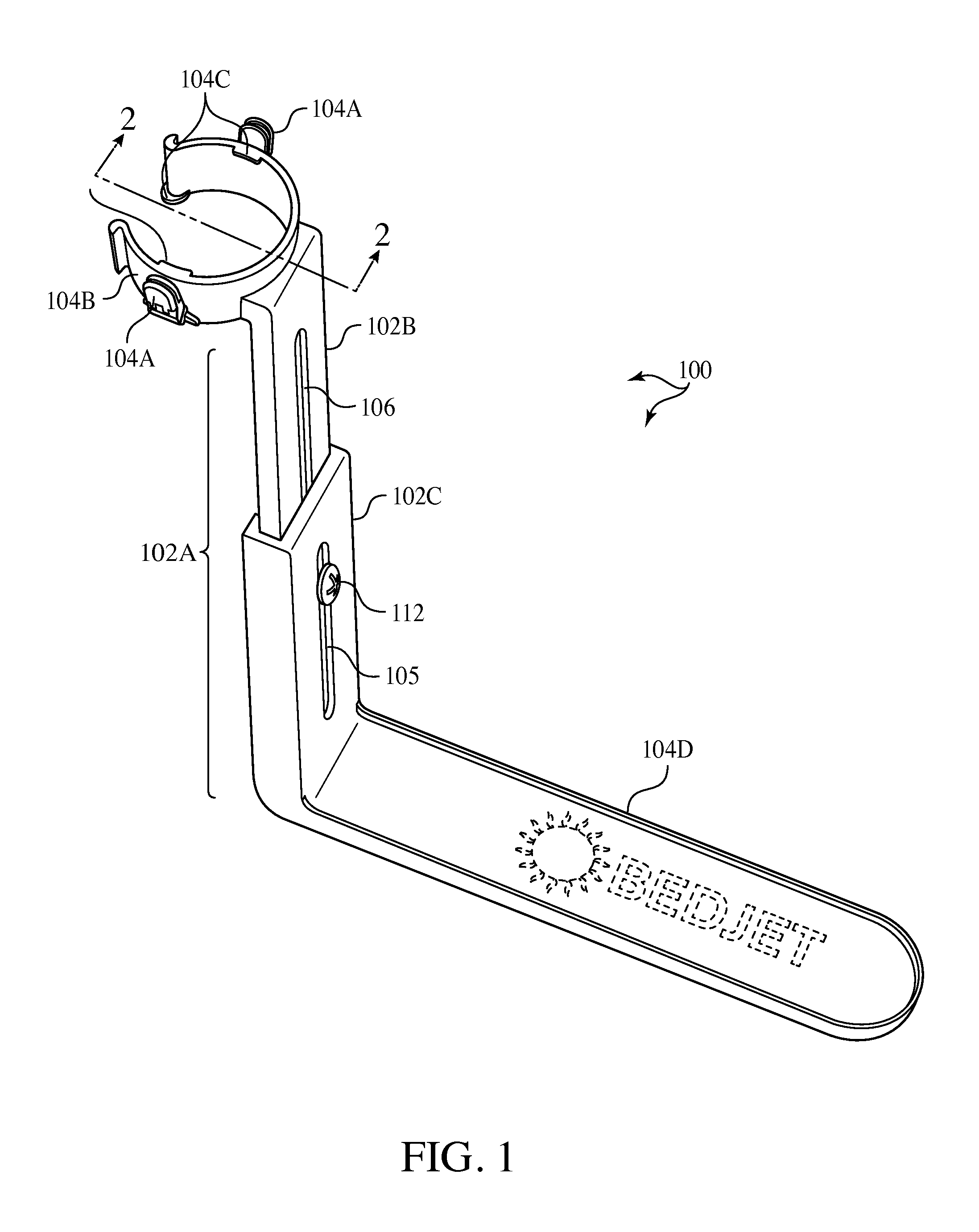
This patent application asserts the benefit of invention priority from the filing on Nov. 6, 2013 of U.S. provisional patent application No. 61/966,042 entitled “Forced air thermal device for a bed with integrated wireless RF remote controls and optional wi-fi/Bluetooth controls”. This patent application incorporates subject matter by reference to copending patent applications of the same inventor as that of the present application: (1) U.S. provisional patent application No. 61/966,042 entitled “Forced air thermal device for a bed with integrated wireless RF remote controls and optional wi-fi/Bluetooth controls. (2) U.S. design patent application Ser. No. 29/501,652 filed Sep. 5, 2014 entitled “AIR DELIVERY OUTLET NOZZLE”. (3) U.S. design patent application Ser. No. 29/501,656 filed Sep. 5, 2014 and entitled “HOUSING FOR A CLIMATE CONTROL APPARATUS”. (4) U.S. design patent application Ser. No. 29/501,647 filed Sep. 5, 2014 and entitled “SLEEVED HOSE”. (5) U.S. utility patent application filed on Nov. 6, 2014 and entitled “REMOTE SETTING AND OPERATION OF A BEDDING CLIMATE CONTROL APPARATUS WITH FORCED AIRFLOW FOR HEATING AND VENTILATING. (6) U.S. utility patent application filed on Nov. 6, 2014 and entitled “BEDDING CLIMATE CONTROL APPARATUS WITH FORCED AIRFLOW FOR HEATING AND VENTILATING”. The invention is a retention unit that is held stationary beneath a mattress and clamps to bed sheets and grasps a flexible hose that delivers tempered air. For a better understanding of the present invention, reference is made to the following description and accompanying drawings, while the scope of the invention is set forth in the appended claims. Turing to the drawing, In the case of Piece 102B is elongated and forms a recess 103 ( In the case of The ring-shaped segment 104 may be closed to grasp about a periphery of the hose to prevent horizontal movement of the flexible hose 116. If the ring-shaped segment 104 is corrugated on its inward facing side, the corrugations are sized to enter grooves on the exterior of the flexible hose 116 to retain the flexible hose 116 in position against relative vertical movement where the retention takes place. The horizontally extending base segment 104D is elongated and will lie beneath a mattress and provides firm support for the performance of the retaining and holding functions. The vertically extending riser segment 104C extends along an end of the mattress at the foot of a bed. The vertically extending riser segment 104C may be height adjustable by being formed of two sliding elements that slide relative to each other vertically and secured in any relative position with respect to each other in any convention manner that two sliding pieces may be retained in their relative position with respect to each other, such as with a series of holes in one of the sliding pieces and a spring-loaded button in the other that enters into one of the series of holes when aligned and can be urged manually against spring bias to leave the hole to free the sliding pieces from their relative position. The bedding climate control apparatus 10 and the flexible hose 116 and the air delivery outlet nozzle 118 may be constructed and operated in accordance with that of U.S. utility patent application filed in November 2014 on the same day as that of the present application and entitled “REMOTE SETTING AND OPERATION OF A BEDDING CLIMATE CONTROL APPARATUS WITH FORCED AIRFLOW FOR HEATING AND VENTILATING, whose contents are incorporated herein by reference, and with that of U.S. utility patent application filed in November 2014 on the same day as that of the present application and entitled “BEDDING CLIMATE CONTROL APPARATUS WITH FORCED AIRFLOW FOR HEATING AND VENTILATING, whose contents are incorporated herein by reference. Further, the air delivery outlet nozzle 118 may be in accordance with by U.S. design patent application Ser. No. 29/501,652 filed Sep. 5, 2014 entitled “AIR DELIVERY OUTLET NOZZLE:, whose contents are incorporated herein by reference. Also, the housing for the bedding climate control apparatus 10 may be in accordance with U.S. design patent application Ser. No. 29/501,656 filed Sep. 5, 2014 and entitled “HOUSING FOR A CLIMATE CONTROL APPARATUS”, whose contents are incorporated herein by reference. In addition, the flexible hose 116 may be in accordance with U.S. design patent application Ser. No. 29/501,647 filed Sep. 5, 2014 and entitled “SLEEVED HOSE”, whose contents are incorporated herein by reference. The flexible hose 116 is a kind of air conduit. Any air conduit may be utilized in accordance with the invention as a substitute for the flexible hose 116 that is shown regardless of the shape of its diametrical cross-section be it circular, rectangular, triangular, pentagonal, hexagonal, octagonal, etc. The air conduit may be considered to terminate into an open end portion as reflected by the air delivery outlet nozzle 118. Although the drawings show a particular shape for the air outlet delivery nozzle 118, the invention is not limited to any particular shape such as that depicted. Instead, any conventional configuration with an opening for the discharge of airflow is envisioned. The two clamps 104A may be of any configuration suited to retain the bed sheets in position that keeps the bed sheet overlaying the air outlet delivery nozzle 18. The horizontally extending base segment 104D is a kind of fixing portion in that it fixes the relative position of the rest of the retention unit when it is in position underneath a mattress that rests upon a surface. Such a fixing portion may be of a one piece unitary construction as shown or be in multiple elongated pieces with each as long as that depicted for the base segment 104D but not as wide yet preferably arranged to lay side by side with each other. The vertically extending riser segment 102A or rising portion may have a configuration different from that depicted in the drawing so long as they are retractable and expandable between fully withdrawn and fully extended positions. For instance, the two pieces may telescope one into the other with each being tubular. Since the air conduit such as the flexible hose 116 is grasped, the two clamps 104A could be attached to the air conduit itself preferably in close proximity to where the ring-shaped segment 104 grasps the air conduit. In that case, the two clamps 104A would be separate from the ring-shaped segment 104 and from the vertically extending riser segment 102A or 104B as the case may be. The two clamps 104A could be attached to a separate ring that grasps the periphery of the air conduit in a manner analogous to that of the ring-shaped segment 104. While the foregoing description and drawings represent the preferred embodiments of the present invention, various changes and modifications may be made without departing from the scope of the present invention. A retention unit that grasps a periphery of a flexible hose and that clamps onto bed sheets to prevent relative movement of the hose and bed sheets where the grasping and clamping takes place. The retention unit includes a grasping portion, a fixing portion, a rising portion and a fixing portion. The rising portion may have at least two pieces mounted in a sliding manner to slide relative to each other so as to separate the grasping portion and the fixing portion from each other and different elevations. The two pieces may be slid relative to each other and held against further relative movement by securing them. The fixing portion is positioned underneath a mattress. 1. A bedding climate control apparatus retention unit, comprising
a retention unit having: grasping means for grasping, in a secure manner with a grasping portion, an air conduit that terminates into an open end portion; fixing means for fixing, with a fixing portion, the air conduit into position with respect to a side of a bed against relative movement; and clamping means for clamping, with a clamping portion, a bed sheet in a position extending over the open end portion of the air conduit even as said grasping means grasps the air conduit in the secure manner. 2. The apparatus of 3. The apparatus of releasable retaining means for releasably retaining the at least two pieces to each other to prevent the at least two pieces from moving relative to each other until manually released from each other. 4. The apparatus of 5. The apparatus of 6. The apparatus of 7. The apparatus of 8. A method to grasp a flexible hose and retain a bed sheet, comprising the steps of:
providing a retention unit having a grasping portion, a fixing portion and a clamping portion; grasping, in a secure manner with the grasping portion an air conduit that terminates into an open end portion; fixing, with the fixing portion, the air conduit into position with respect to a side of a bed against relative movement; and clamping, with the clamping portion, a bed sheet in a position extending over open end portion of the air conduit even as the grasping portion grasps the air conduit in the secure manner. 9. The method of separating said fixing portion from said grasping and clamping portion with a rising portion to define a separation distance, the grasping and the fixing portions each extending in opposite directions from the rising portion relative to each other. 10. The method of moving at least two pieces of the rising portion with respect to each other through a plurality of relative positions so as to vary an amount of the separation distance between the fixing portion and the grasping and clamping portions; and retaining the at least two pieces to each other in a releasable manner to prevent the at least pieces from moving relative to each other until manually released from each other. 11. The method of tightening a fastener to press against outward facing surfaces of the at least two pieces to carry out the retaining of the at least two pieces in a fixed relative position to each other. 12. The method of 13. The method of 14. The method of CROSS-REFERENCE TO COPENDING PATENT APPLICATIONS
INCORPORATION BY REFERENCE TO COPENDING PATENT APPLICATIONS
BACKGROUND OF THE INVENTION
Technical Field of the Invention
BRIEF DESCRIPTION OF THE DRAWING
DETAILED DESCRIPTION OF THE INVENTION