METHOD OF SETTING FLYING HEIGHT AND FLYING HEIGHT SETTING DEVICE
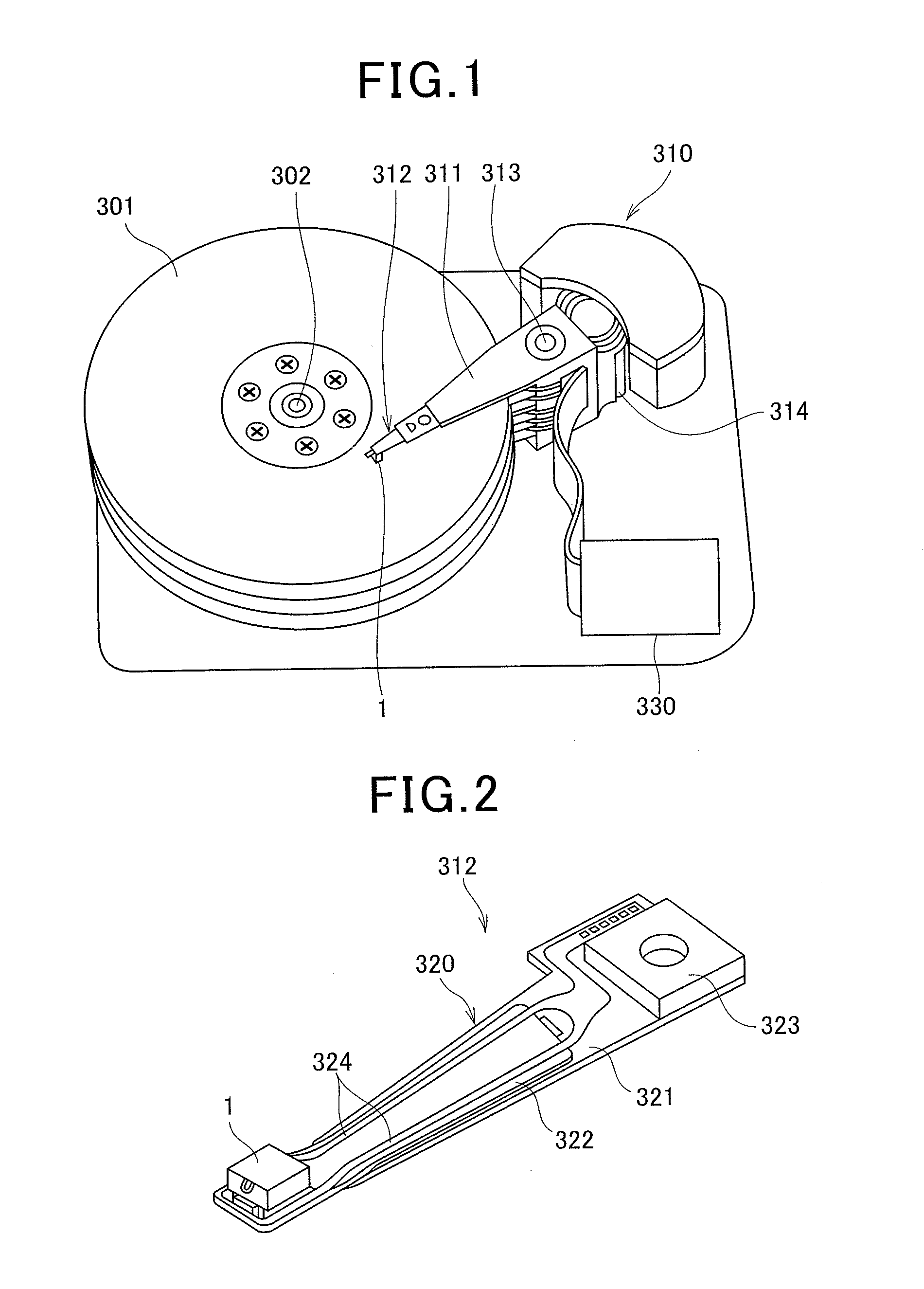
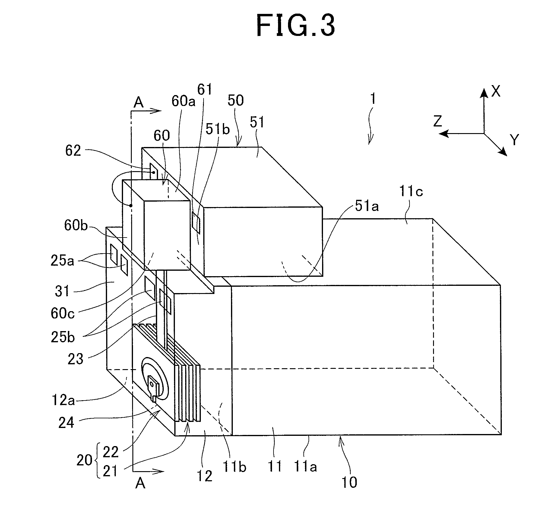
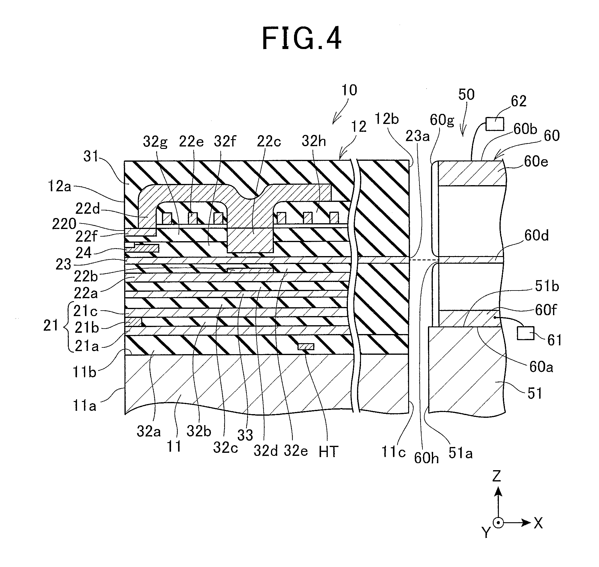
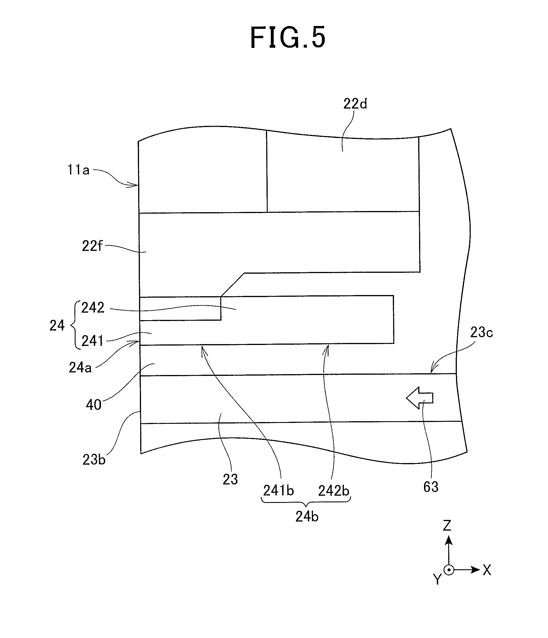
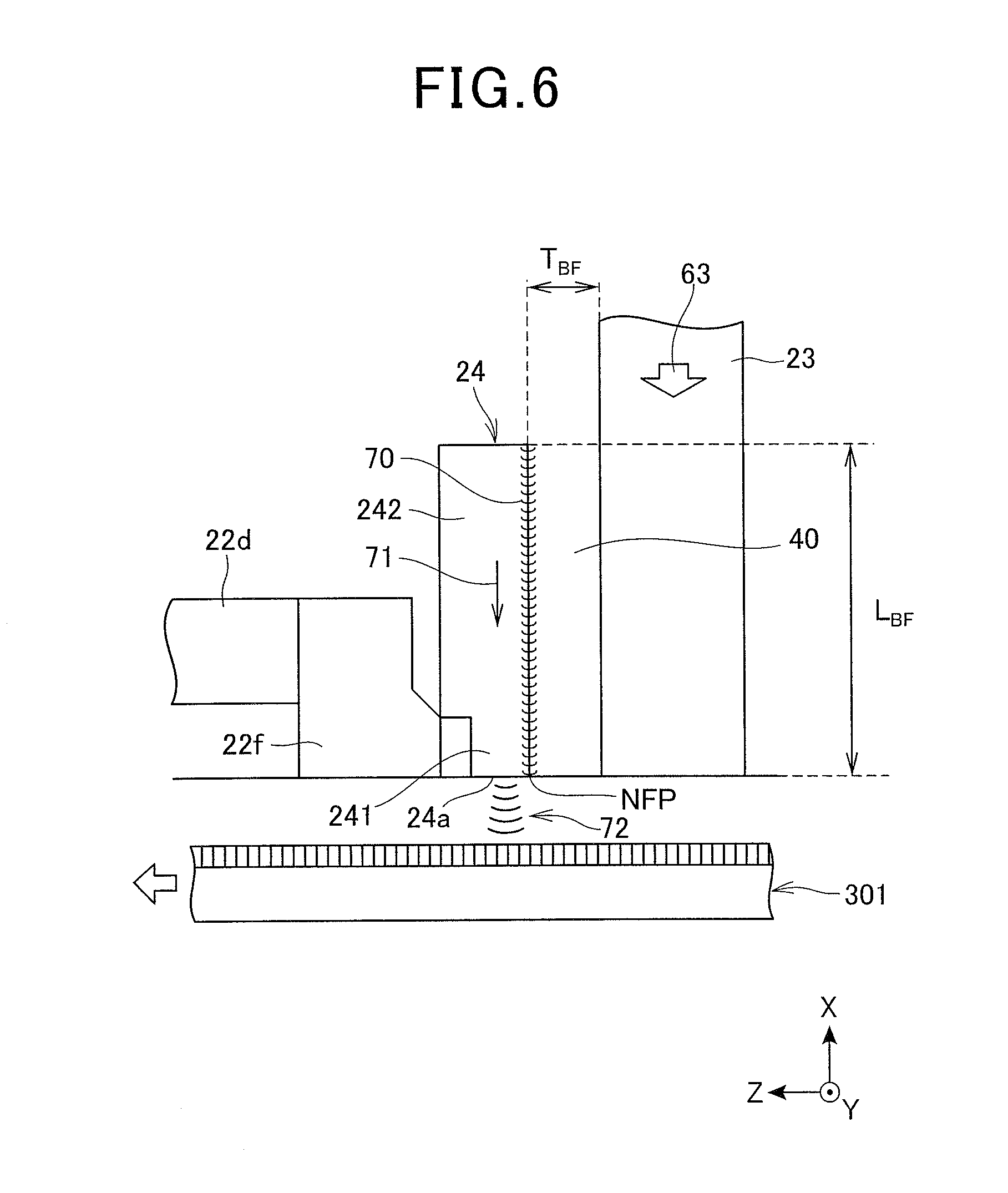
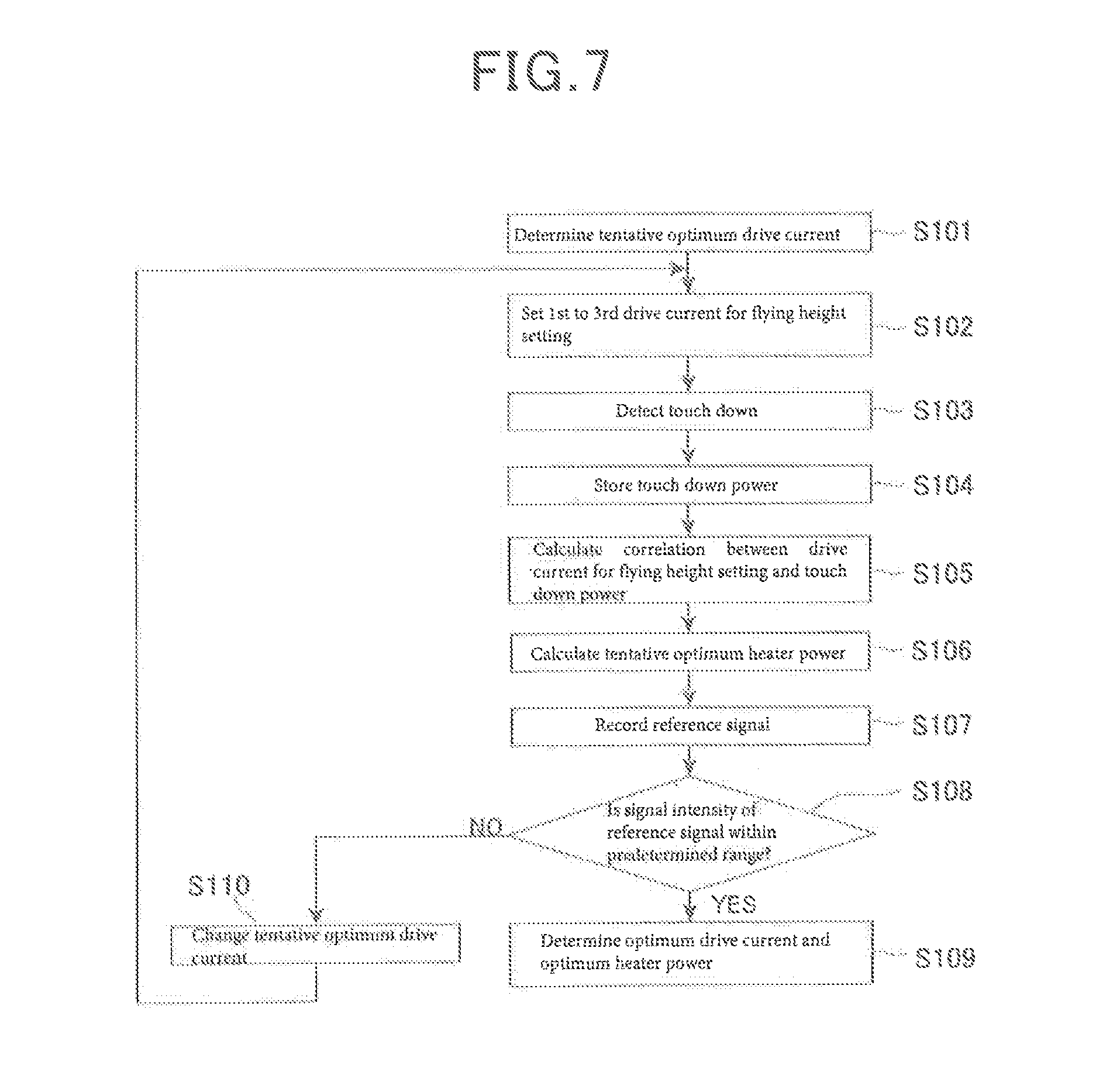
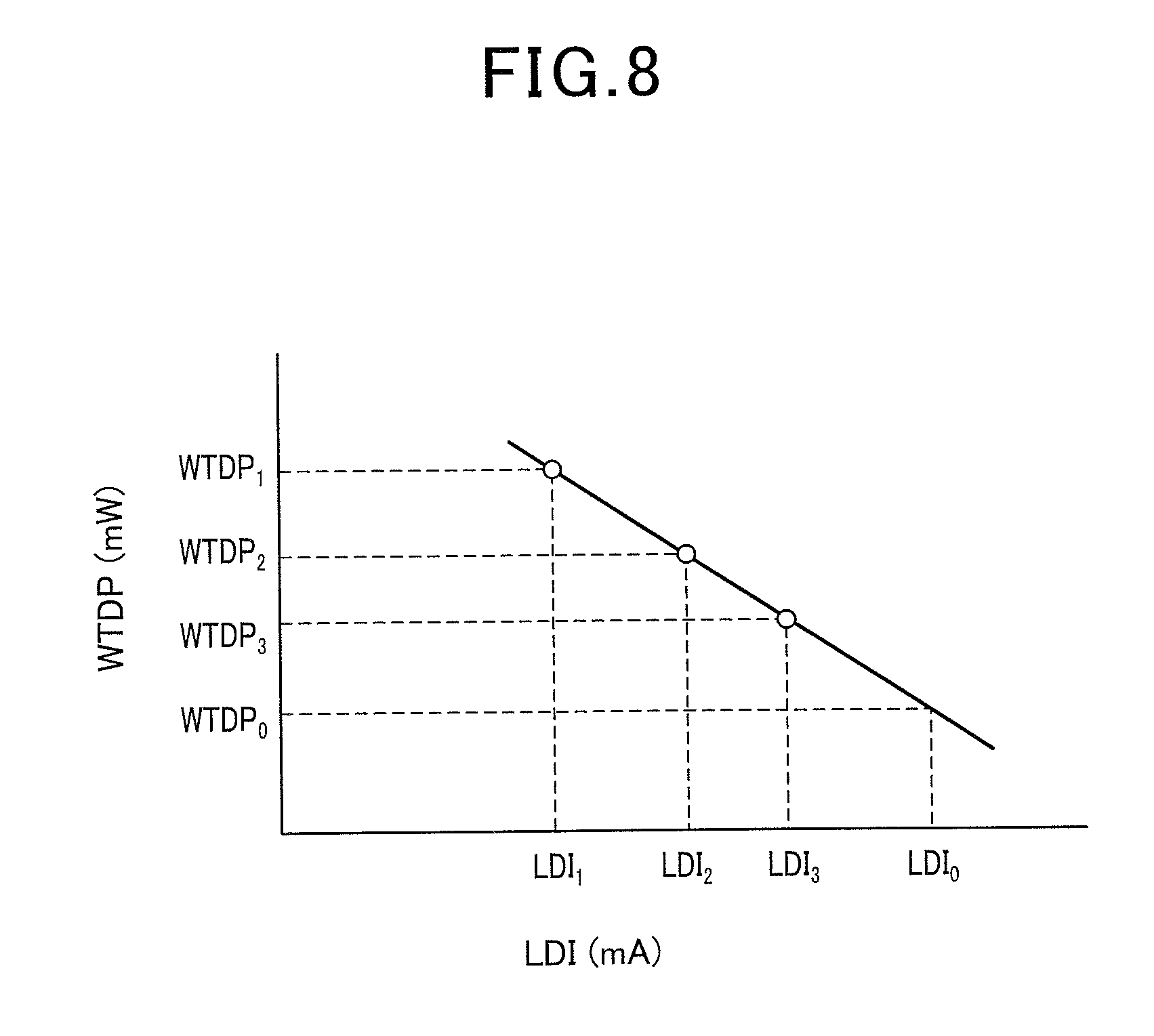
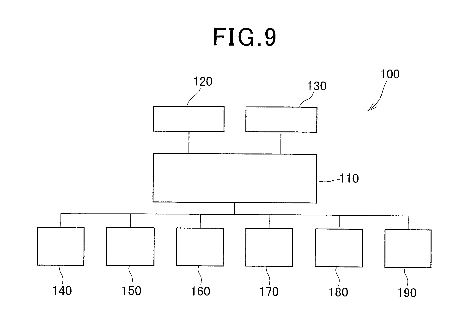
The present invention relates to a method for setting the flying height of a thermally-assisted magnetic recording head, and a device for setting the flying height in a magnetic recording device including a thermally-assisted magnetic recording head that irradiates near-field light to a magnetic recording medium, and that decreases the anisotropy field of the magnetic recording medium to record data. In the field of magnetic recording using a head and a medium, further performance improvement of thin film magnetic heads and magnetic recording media is in demand in association with the high recording density of magnetic disc devices. As a thin film magnetic head, at present, a composite type thin film magnetic head made of a structure where a magnetoresistant (MR) element for reading and an electromagnetic transducer element for writing are laminated is widely used. The magnetic recording medium is a discontinuous medium in which magnetic grains are aggregated, and each magnetic grain has a single magnetic domain structure. In the magnetic recording medium, one recording bit is configured by a plurality of magnetic grains. Consequently, in order to enhance the recording density, asperities at the border between adjacent recording bits need to be reduced by decreasing the size of the magnetic grains. However, if the magnetic grains are reduced in size, there is the problem that the thermal stability of magnetization of the magnetic grains is reduced in association with a decrease in the volume of the magnetic grain. As a countermeasure against this problem, an increase of magneto anisotropy energy Ku of magnetic grains may be considered; however, the increase of Ku results in an increase in an anisotropy field (coercive force) of a magnetic recording medium. On the other hand, the upper limit of the recording magnetic field intensity of the thin film magnetic head is substantially determined by saturation magnetic flux density of a soft magnetic material configuring a magnetic core within the head. Consequently, if the anisotropy field of the magnetic recording medium exceeds the acceptable value determined by the upper limit of the recording magnetic field intensity, it becomes impossible to write to the magnetic recording medium. Currently, as a method to solve such a thermal stability problem, a so-called thermally assisted magnetic recording method is proposed in which a recording magnetic field is applied to record information under a state where the anisotropy field is reduced by heating the magnetic recording medium while a magnetic recording medium made from a magnetic material with large Ku is used. In this thermally assisted magnetic recording method, a method using a near-field light probe, or so-called plasmon-generator, comprising a metal piece that generates NF light from plasmon excited by laser light is generally known, and as a magnetic head including such a plasmon-generator, a magnetic head including a magnetic pole, a waveguide and a plasmon-generator facing the waveguide is proposed. In a thermally-assisted magnetic recording head, light propagated through the waveguide is coupled with a plasmon-generator in a surface plasmon mode, and excites the surface plasmon. Propagation of such surface plasmon in the plasmon-generator causes the generation of near-field light at the near-field light generating portion positioned at the end portion of the plasmon-generator at the medium opposed surface side. Then, a magnetic recording medium is heated by irradiating the magnetic recording medium with the near-field light generated at the near-field light generating portion of the plasmon-generator, and information is recorded by applying a magnetic field under a state where the anisotropy field of the magnetic recording field is decreased. In a thermally-assisted magnetic disk device including such a thermally-assisted magnetic recording head, the distance between the thermally-assisted magnetic recording head and the magnetic recording medium, i.e., the flying height of the thermally-assisted magnetic recording head relative to the magnetic recording medium, is an important parameter to satisfy demands, such as reduction of the bit error rate (BER) or high recording density. Recently, in order to respond to demands, such as high recording density, a technology is proposed in which a medium opposed surface of the thermally-assisted magnetic recording head toward the magnetic recording medium side is protruded by heat-expanding the surface due to the heat generation of a heater and the like, and the flying height of the thermally-assisted magnetic recording head relative to the magnetic recording medium is reduced (see for example, JP 2010-79978). In the patent literature (JP 2010-79978), it is disclosed that the protrusion amount of the medium opposed surface is controlled by controlling the power supply to the heater, and the optimum flying height (the target flying height) can be realized. However, in a thermally-assisted magnetic disk device, in addition to the protrusion of the medium opposed surface due to supply of power to the heater and the application of writing current, since the medium opposed surface also protrudes due to the generation of near-field light, it is actually difficult to reduce the target flying height to approximately several nm (approximately 2 nm). In the technology disclosed in the patent literature, the supply of power to the heater that can accomplish the target flying height can be set by a touch down test of the thermally-assisted magnetic recording head. In other words, the medium opposed surface gradually protrudes while the supply of power to the heater is increased, contact (touch down) between the thermally-assisted magnetic recording head and the magnetic recording medium is detected, and the supply of power to the heater that can accomplish the target flying height is determined. In the meantime, in a thermally-assisted magnetic recording head, when a signal is recorded, the near-field light generated at the plasmon-generator is irradiated to the magnetic recording medium. In association with the generation of the near-field light, the vicinity of the medium opposed surface of the thermally-assisted magnetic recording head is heated, and the medium opposed surface protrudes toward the magnetic recording medium side. Therefore, taking into consideration the protrusion of the medium opposed surface of the thermally-assisted magnetic recording head due to the near-field light, it is necessary to set a supply of power to the heater that can accomplish the target flying height. It is an object of the present invention to provide a method and device for setting the flying height of the thermally-assisted magnetic head, in a thermally-assisted magnetic recording device having a thermally-assisted magnetic recording head that take into consideration protrusion of a medium opposite surface of the thermally-assisted magnetic head due to heat generation by light for heating a magnetic disk. In order to accomplish this objective, the present invention provides a method for setting a flying height of a thermally-assisted magnetic recording head relative to a magnetic recording medium in a thermally-assisted magnetic recording device, including: a magnetic recording medium, a thermally-assisted magnetic recording head, and a positioning device that supports the thermally-assisted magnetic recording head, and that positions the thermally-assisted magnetic recording head relative to the magnetic recording medium, wherein the thermally-assisted magnetic recording head includes: a magnetic pole that generates a writing magnetic field from an end surface that forms a portion of a medium opposed surface facing the magnetic recording medium, a waveguide where light for exciting surface plasmon propagates, a plasmon-generator that generates near-field light from a near-field light generating portion on a near-field light generating end surface that forms a portion of the medium opposed surface by coupling with the light in the surface plasmon mode, a light source part that irradiates the waveguide with light by applying a predetermined drive current, and a heater part that heats the vicinity of the medium opposed surface in order to protrude the medium opposed surface toward the magnetic recording medium side, wherein the setting method comprising the steps of: determining a tentative optimum drive current that is supplied to the light source part, and setting 1st to nth drive currents for flying height setting (n is an integer of 2 or more) where values are smaller than the tentative optimum drive current, and increase sequentially; supplying heater power to the heater part while supplying the 1st to nth drive currents for flying height setting to the light source part to protrude the medium opposed surface of the thermally-assisted magnetic recording head toward the magnetic recording medium side, and detecting touch down of the thermally-assisted magnetic recording head; storing the heater power that is supplied to the heater part when the touch down of the thermally-assisted magnetic recording head is detected as touch down power; calculating a correlation between the 1st to nth drive currents for flying height setting and the touch down power, determining a tentative optimum heater power to be supplied to the heater when the tentative optimum drive current is supplied to the light source part so as to set the flying height to be a target flying height; supplying the tentative optimum drive current to the light source part, supplying the tentative heater power to the heater part, and recording a reference signal on the magnetic recording medium; and determining whether or not the reference signal is recorded with a the desired signal intensity, wherein if it is determined that the reference signal is not recorded with the desired signal intensity, while the current values of the tentative optimum drive current and the 1st to nth drive currents for flying height setting are changed to greater current values, a series of steps from the step of detecting the touch down to the step of determination are repeated until the reference signal is recorded at the desired signal intensity, and when it is determined that the reference signal is recorded with the desired signal intensity, the tentative optimum drive current at that time and tentative heater power determined based on the correlation are determined as the optimum drive current to be supplied to the light source part and the optimum heater power to be supplied to the heater part, respectively (Invention 1). The vicinity of a medium opposed surface is heated by near-field light that is irradiated from the near-field light generating portion of the thermally-assisted magnetic recording head to a magnetic recording medium, and the medium opposed surface protrudes toward the magnetic recording medium side. It has become ascertained according to keen study by the inventors that the spot diameter of the near-field light may become smaller responding to demand of high recording density in recent years, and that the protrusion shape of the medium opposed surface attributable to heat in association with generation of the near-field light becomes precipitous. If the protrusion shape of the medium opposed surface of the thermally-assisted magnetic recording head is precipitous, the contact area with the magnetic recording medium in the thermally-assisted magnetic recording head becomes extremely small, so it may become difficult to precisely detect touch down relative to the magnetic recording medium of the thermally-assisted magnetic recording head can occur. If it becomes difficult to detect touch down, as a result of pushing the thermally-assisted magnetic recording head into the magnetic recording medium so as to make touch down detectable, the thermally-assisted magnetic recording head and the magnetic recording medium may be damaged. In the invention (Invention 1), touch down relative to the magnetic recording medium of the thermally-assisted magnetic recording head can be assuredly detected by touching down the thermally-assisted magnetic recording head while near-field light is generated by a drive current for setting the flying height, which is smaller than the drive current supplied to the light source to be a source for generating the near-field light. Therefore, optimum heater power that is supplied to the heater part and optimum drive current supplied to the light source in order to accomplish target flying height can be determined without causing damage to the magnetic recording medium and the thermally-assisted magnetic recording head. As a result, the flying height of the thermally-assisted magnetic recording head can be set to the target flying height. In the invention above (Invention 1), current values of the 1st to nth drive currents for flying height setting can all be set to 70% or less of the current value of the tentative optimum drive current (Invention 2) or preferably 60% or less (Invention 3). Further, in the above invention (Invention 1), the current values of the 1st to nth drive currents for flying height setting can be set within the range of 30% to 70% of the current value of the tentative optimum drive current (Invention 4), or preferably within the range of 30% to 60% (Invention 5). In the above invention (Invention 1), the thermally-assisted magnetic head further includes a writing coil for generating a writing magnetic field in the magnetic pole, and it is preferable to conduct the step of detecting touch down under a state where write current is supplied to the writing coil (Invention 6). Further, the present invention provides a device for setting a flying height of a thermally-assisted magnetic recording head relative to a magnetic recording medium in a thermally-assisted magnetic recording device, including: the magnetic recording medium, the thermally-assisted magnetic recording head, and a positioning device that supports the thermally-assisted magnetic recording head, and that positions the thermally-assisted magnetic recording head relative to the magnetic recording medium, wherein the thermally-assisted magnetic recording head includes: a magnetic pole that generates a writing magnetic field from an end surface that forms a portion of a medium opposed surface facing the magnetic recording medium, a waveguide where light for exciting surface plasmon propagates, a plasmon-generator that generates near-field light from a near-field light generating portion on a near-field light generating end surface that forms a portion of the medium opposed surface by coupling with the light in a surface plasmon mode, a light source that irradiates the waveguide with light by applying a predetermined drive current, and a heater part that heats the vicinity of the medium opposed surface in order to protrude the medium opposed surface toward the magnetic recording medium side, wherein the flying height setting device includes: a drive current determination part that determines a tentative optimum drive current that is supplied to the light source part, and that determines 1st to nth drive currents for flying height setting (n being an integer of 2 or more) where values of the drive currents are smaller than the tentative optimum drive current, and increase sequentially, a touch down detection part that detects touch down of the thermally-assisted magnetic recording medium; a storage part that stores the heater power, which is supplied to the heater part when the touch down of the thermally-assisted magnetic recording head is detected by the touch down detection part; a correlation calculation part that calculates correlation between the 1st to nth drive currents for flying height setting and the touch down power; a tentative optimum heater power determination part that determines tentative optimum heater power to be supplied to the heater part when the tentative optimum drive current is supplied to the light source part based on the correlation, so as to set the flying height as a target flying height; and a determination part that supplies the tentative optimum drive current to the light source part, and that supplies the optimum heater power to the heater part, and that determines whether or not a reference signal recorded in the magnetic recording medium is recorded with a desired signal intensity (Invention 7). According to the present invention, a method for setting flying height of the thermally-assisted magnetic recording head and a device for setting the flying height can be provided in the thermally-assisted magnetic recording device having a thermally-assisted magnetic recording head considering protrusion of a medium opposed surface of the thermally-assisted magnetic recording head due to heat generation by a light for heating the magnetic disk. Before explaining an embodiment of the present invention, terms used herein are defined. In a laminated structure or an element structure formed on an element formation surface of a slider substrate of the thermally-assisted magnetic recording head relating to one embodiment of the present invention, a substrate side is regarded as “downward” and its opposite side is regarded as “upward”, viewed from a layer or an element that is a reference. Further, the medium opposed surface side is regarded as “forward” and its opposite side is regarded as “back side” or “backward” viewed from a layer or an element that is a reference. In addition, in the magnetic recording head relating to one embodiment of the present invention, as needed, in some drawings, “X, Y and Z-axis directions” are referenced. Herein, the Z-axis direction is “vertical direction” as mentioned above, and +Z side is equivalent to a trailing side, and −Z side is equivalent to a leading side. Further, the Y-axis direction is the track width direction, and the X-axis direction is the height direction. When explaining the flying height setting method of the thermally-assisted magnetic recording head in the thermally-assisted magnetic recording device relating to one embodiment of the present invention, a thermally-assisted magnetic disk device having a thermally-assisted magnetic recording head as the subject of setting the flying height is explained. <Thermally-Assisted Magnetic Disk Device> As shown in In the present embodiment, the magnetic disk 301 is for perpendicular magnetic recording, and has a structure where a soft magnetic under layer, an intermediate layer and a magnetic recording layer (perpendicular magnetization layer) are sequentially laminated on a disk substrate. The assembly carriage device 310 is a device for positioning the thermally-assisted magnetic recording head 1 on a track of the magnetic disk 301. In the assembly carriage device 310, the drive arms 311 are stacked in a direction along a pivot bearing axis 313, and are angularly pivotable by a voice coil motor (VCM) 314 to set a pivot bearing shaft 313 as the center. Furthermore, the structure of the magnetic disk device in the present embodiment is not limited to the structure described above, but the magnetic disk 301, the drive arm 311, the HGA 312 and the thermally assisted magnetic recording head 1 may be singular, respectively. In the HGA 312 shown in As shown in Further, the light source unit 50 is formed from AlTiC (Al2O3—TiC) and the like, and includes a unit substrate 51 having an adhering surface 51 Herein, the slider 10 and the light source unit 50 are mutually adhered, while a rear surface 11 The head part 12 formed on the element formation surface 11 of the slider substrate 11 includes a head element 20 having an MR element 21 for reading data from the magnetic disk 301 and an electromagnetic transducer element 22 for writing data onto the magnetic disk 301, a waveguide 23 for guiding laser light from the laser diode 60 included in the light source unit 50 to the medium opposed surface side, a plasmon-generator 24 configuring a near-field light generation optical system along with the waveguide 23, a protection layer 31 formed on the element formation surface 11 Respective ends of the MR element 21, the electromagnetic transducer element 22, the plasmon-generator 24 and the waveguide 23 reach a head part end surface 12 Upon actual writing or reading, the thermally-assisted magnetic recording head 1 hydrodynamically flies on the rotating magnetic disk 301 surface at a predetermined flying height. In this situation, end surfaces of the MR element 21 and the electromagnetic transducer element 22 face a surface of the magnetic recording layer of the magnetic disk 301 via appropriate magnetic spacing. In this situation, the MR element 21 senses a data signal magnetic field from the magnetic recording layer and performs reading, and the electromagnetic transducer element 22 applies a data signal magnetic field to a magnetic recording layer and performs writing. A flying height in this case is a very important parameter when characteristics must be demonstrated, such as high recording density. In the present embodiment, it is possible to fly the thermally-assisted magnetic recording head 1 stably at an extremely small flying height (for example, approximately 2 nm) by setting a flying height using a method described later. When writing, laser light that has propagated through the waveguide 23 from the laser diode 60 of the light source unit 50 is coupled with the plasmon-generator 24 in a surface plasmon mode, and excites the surface plasmon in the plasmon-generator 24. Near-field light is generated at the end portion of the plasmon-generator 24 at the head part end surface 12 As shown in The lower side shield layer 21 The MR multilayer body 21 When the MR multilayer body 21 The head part 12 in the present embodiment includes a non-magnetic layer 32 The electromagnetic transducer element 22 includes a lower side yoke layer 22 The head part 12 in the present embodiment includes a dielectric layer 32 In the head part 12 of the present embodiment, the lower side yoke layer 22 It is preferable that the magnetic pole 22 Further, the width of the magnetic pole 22 The end surface of the upper side yoke layer 22 The writing coil 22 The lower side yoke layer 22 The waveguide 23 extends to a front end surface 23 The buffer portion 40 fulfills a role to couple laser light propagating in the waveguide 23 with plasmon-generator 24 in a surface plasmon mode. Furthermore, the buffer portion 40 may be a portion of the dielectric layer 32 Furthermore, specific configurations of the magnetic pole 22 A heater part HT is incorporated at the back side of the head part end surface 12 As shown in As the laser diode 60, substances that are normally used for communication, such as InP-series, GaAs-series or GaN-series, for optical system disk storage or for material analysis, are usable, and wavelength λL4of the laser light to be radiated should be within the range of, for example, 375 nm to 1.7 μm. Specifically, for example, InGaAsP/InP quaternion mixed crystal system laser diode where its possible wavelength range is identified as 1.2 μm to 1.67 μm is also usable. The laser diode 60 has a multilayer structure including an upper side electrode 60 Further, in driving of this laser diode 60, a power source within a magnetic disk device is usable. In actuality, the magnetic disk device normally includes a power source of, for example, approximately 5 V, and has sufficient voltage for the laser oscillation operation. Further, consumption power of the laser diode 60 is also, for example, approximately several dozens of mW, and it can be covered with a power source within the magnetic disk device. In actuality, a predetermined voltage is applied between the first drive terminal electrode 61 that is electrically connected to the lower side electrode 60 Although the sizes of the slider 10 and the light source unit 50 are variable, and for example, the slider 10 may be a so-called femto slider with 700 μm of width in a track width direction (Y-axis direction)×850 μm of length (in Z-axis direction)×230 μm of thickness (in X-axis direction). In this case, the light source unit 50 may be slightly smaller than this, for example, 425 μm of width in a track width direction×300 μm of length and×300 μm of thickness. The thermally-assisted magnetic recording head 1 is configured by connecting the light source unit 50 with the slider 10. In this connection, the adhering surface 51 Next, specific configuration of the waveguide 23, the plasmon-generator 24 and the magnetic pole 22 As shown in The plasmon-generator 24 has near-field light generating end surface 24 Furthermore, in the present embodiment, a side surface of the waveguide 23 refers to an end surface other than the front end surface 23 More specifically, the laser light (waveguide light) that has progressed to the vicinity of the buffer portion 40 is coupled with optical configuration of the waveguide 23 having a predetermined refractive index nWG, the buffer portion 40 having a predetermined refractive index nBF and the plasmon-generator 24 made from a conductive material, such as metal, to induce the surface plasmon mode on the lower surface 24 Space (thickness of the buffer portion 40 immediately under the plasmon-generator 24) between the upper surface of the waveguide 23 (opposite surface from the plasmon-generator 24) and the lower surface 24 The plasmon-generator 24 has a first PG part 241 extending in the perpendicular direction relative to the ABS 11 The lower surface 241 In the plasmon-generator 24, the second PG part 242 has a front end portion continuing to the first PG part 241 and a rear end portion positioned at farther back side than the front end portion. Then, width of the plasmon-generator 24 (second PG part 242) in the track width direction (Y-axis direction) is gradually increased from the front end portion of the second PG part 242 toward the rear end portion. The surface plasmon is efficiently excited on the lower surface 242 As the shape of the waveguide 23, the width in the track width direction (Y-axis direction) may be constant, but the width in the track width direction (Y-axis direction) in a portion positioned in the vicinity of the ABS 11 The upper surface 23 Further, the waveguide 23 has a multilayer structure of the dielectric material, and may have a structure where the more refractive index becomes higher as the elevation at which the layer is situated increases. For example, such multilayer structure is realized by sequentially laminating dielectric materials where a composition ratio of X and Y values in SiOXNY are appropriately changed. The number of laminations may be set to, for example, 8 layers to 12 layers. As a result, when laser light (waveguide light) is a linearly polarized light in the Z-axis direction, the laser light (waveguide light) can be propagated to the buffer portion 40 side in the Z-axis direction. On this occasion, a desired propagation position in the Z-axis direction of the laser light (waveguide light) can be realized by selecting a composition, layer thickness and the number of layers of each layer in this multilayer structure. The buffer portion 40 is formed from a dielectric material having a lower refractive index nBF than the refractive index nWG of the waveguide 23. For example, when wavelength λL of the laser light is 600 nm and the waveguide 23 is formed from Al2O3 (alumina; n=1.63), the buffer portion 40 may be made from SiO2 (silicon dioxide; n=1.46). Further, when the waveguide 23 is formed from Ta2O5 (n=2.16), the buffer portion 40 may be made from SiO2 (SiO2; n=1.46) or Al2O3 (n=1.63). In these cases, this buffer portion 40 can be a portion of the dielectric layer 32 The magnetic pole 22 <Operation of Thermally-Assisted Magnetic Recording Head> Next, operation of the thermally-assisted magnetic recording head 1 relating to the present embodiment having the configuration above is explained. As shown in In this induced surface plasmon mode, the surface plasmon 70 is excited on the lower surface 24 Thus, the surface plasmon 70 propagates in the direction of the arrow 71, and the surface plasmon 70, i.e., an electric field shall be focused onto the near-field light generating portion NFP on the near-field light generating end surface 24 The near-field light 72 generated as mentioned above is irradiated toward the magnetic recording layer of the magnetic disk 301, reaches the surface of the magnetic disk 301, and heats the magnetic recording layer portion of the magnetic disk 301. This results in reduction of the anisotropy field (coercive force) in that portion to a value that enables writing to be performed, and writing is performed by the magnetic field applied to that portion. Upon writing, regarding the space between the head part end surface 12 Herein, due to the generation of the near-field light 72, heat is generated in the vicinity of the near-field light generating portion NFP on the near-field light generating end surface 24 <Flying Height Setting Method> Subsequently, in the thermally-assisted magnetic disk device having the configuration above, a method for setting flying height of the thermally-assisted magnetic recording head is explained. First, the thermally-assisted magnetic disk device having the configuration above, which is a subject for setting the flying height, is prepared. Then, a tentative optimum drive current LDI0 that is supplied to the laser diode 60 in the thermally-assisted magnetic recording head 1 is determined (S101). The tentative optimum drive current LDI0 is a drive current that is predicted where it is possible to generate near-field light with predetermined light intensity and spot diameter from the near-field light generating portion NFP of the thermally-assisted magnetic recording head 1 that has flown with the target flying height, and it can be determined to any current value considering rated current of the laser diode 60. Next, 1st to 3rd drive currents for flying height setting LDI1 to LDI3 that are smaller than the tentative drive current LDI0 determined in S101 (for example, 50%, 60% and 70% of the tentative optimum drive current LDI0 determined in S101) are set (S102). Then, the 1st drive current for flying height setting LDI1 (a current, which is 50% of the tentative optimum drive current LDI0 determined in S101) is supplied to the laser diode 60, and near-field light is generated. Under that situation, a write current IW is supplied to the writing coil 22 When the tentative optimum drive current LDI0 determined in S101 is supplied to the laser diode 60 and near-field light is generated, protrusion shape of the head part end surface 12 The 1st to 3rd drive currents for flying height setting LDI1 to LDI3 can be set within the range of 30% to 70% of the tentative optimum drive current determined in S101, preferably 30% to 70%, more preferably 50% to 70%, and particularly preferably 50% to 60%. If the 1st drive current for flying height setting LDI1 is less than 30% of the tentative optimum drive current LDI0 determined in S101, due to the correlation described later, when touch down power WTDP corresponding to the tentative optimum drive current LDI0 determined in S101 is calculated, an error is likely to be too large. In the meantime, if the 3rd drive current for flying height setting LDI3 exceeds 70% of the tentative optimum drive current LDI0 determined in S101, the protrusion shape of the medium opposed surface becomes precipitous, and it is likely to be difficult to detect touch down. Furthermore, the mth drive current for flying height setting (m is one or greater of integer), which is M % of the tentative optimum drive current LDI0, can be calculated with the following formula: In the formula above, Ith represents “current (threshold current) starting laser oscillation in the laser diode 60”. As the method for detecting the touch down, there is no particular restriction, but a conventionally-known method can be applied. For example, a method for detecting torque upon touch down by a sensor provided at the front end portion of the suspension 320 and the like, and a method for detecting elastic wave upon touch down by an AE sensor and the like, can be applied as the method for detecting the touch down. Then, when the touch down is detected, the heater power HTP supplied to the heater part HT is stored as touch down power WTDP1 (S104). A series of steps in S103 and S104 above are conducted by supplying the 2nd and 3rd drive current for flying height setting LDI2 and LDI3 (60% and 70% of the drive currents of the tentative optimum drive current LDI0 determined in S101) to the laser diode 60, respectively. Then, correlation between the touch down power WTDP stored in S104 and the drive current for flying height settings LDI is obtained (S105). For example, as shown in From the correlation obtained as mentioned above, tentative optimum heater power HTP0, which is heater power HTP corresponding to the tentative optimum drive current LDI0 determined in S101, and where the flying height of the thermally-assisted magnetic recording head 1 is a target flying height (for example, 2 nm), is obtained (S106). As shown in Furthermore, the relationship of the change volume of the protrusion amount of the head part end surface 12 The tentative optimum heater power HTP0 obtained as mentioned above is supplied to the heater part HT, the tentative optimum drive current LDI0 determined in S101 is supplied to the laser diode 60 and a reference signal is recorded in the magnetic disk 301 (S107). Then, the reference signal is reproduced, and it is determined whether or not the signal intensity of the reference signal is within a desired range (S108). For example, according to whether or not SNR of the reference signal is a desired value or greater, it can be determined whether or not the signal intensity of the reference signal is within the desired range. If the tentative optimum drive current LDI0 determined in S101 is a drive current, which can generate near-field light required for recording to the desired signal in the thermally-assisted magnetic recording head 1, the reference signal should be recorded into the magnetic disk 301 with the desired signal intensity. In the meantime, if the tentative optimum drive current LDI0 determined in S101 is not enough to generate near-field light required for recording the desired signal, the signal intensity of the reference signal is out of the desired range. In other words, whether or not the tentative optimum drive current LDI0 determined in S101 is an optimum drive current LDIOP that can realize characteristics (such as writing characteristic) of the thermally-assisted magnetic recording head 1 can be determined by the signal intensity of the reference signal recorded in S107 above. In S108 above, when it is determined that the signal intensity of the reference signal is within the desired range (S108, Yes), the tentative optimum drive current LDI0 determined in S101 is determined as the optimum drive current LDIOP that is supplied to the laser diode 60, and the tentative optimum heater power HTP0 determined in S106 is determined as the optimum heater power HTPOP that is supplied to the heater part HT (S109). While the flying height of the thermally-assisted magnetic recording head 1 is set to the target flying height that can respond to the high recording density, a desired signal can be recorded, by supplying the optimum drive current LDIOP determined as mentioned above to the laser diode 60, and by supplying the optimum heater power HTPOP to the heater part HT. In the meantime, if it is determined that the signal intensity of the reference signal is not within the desired range in S108 above (S108, No), the 4th drive current for flying height setting LDI4 that is greater than the 3rd drive current for flying height setting LDI3 is presumed, for example, as 70% of the current of the optimum drive current LDIOP, and then the steps in S103 to S107 are conducted again. In other words, the tentative optimum drive current LDI0 determined in S101 is changed to a greater current value, and the steps in S102 to S107 are conducted again. For example, a current value where a current value for the 3rd drive current for flying height setting LDI3 is divided by 0.9 can be set as a current value for the 4th drive current for flying height setting LDI4. Then, until it is determined that the signal intensity of the reference signal is within the desired range in S108 (S108, Yes), the tentative optimum drive current LDI0 determined in S101 is changed to a greater current value, and the steps in S102 to S107 are repeated. Thus, the optimum drive current LDIOP and the optimum heater power HTPOP in the thermally-assisted magnetic recording head 1 are obtained. Thus, according to the flying height setting method relating to the present embodiment, the optimum drive current LDIOP and the optimum heater power HTPOP where the target flying height is accomplishable per thermally-assisted magnetic recording heads 1 individually having processing variation, and that can respond to the demand for the high recording density can be obtained without damaging the thermally-assisted magnetic recording head 1 and the magnetic disk 301. <Flying Height Setting Device> Subsequently, a flying height setting device where the flying height setting method can be implemented is explained. As shown in The control part 110 is connected to the ROM 120, the RAM 130, the drive current control part 140, the write current control part 150, the heater power control part 160, the VCM control part 170, the SPM control part 180 and the touch down detection part 190, and produces a control signal for operating the drive current control part 140, the write current control part 150, the heater power control part 160, the VCM control part 170, the SPM control part 180 and the touch down detection part 190 based on various programs stored in the ROM 120. Further, the control part 110 calculates the drive currents for flying height setting LDI1 to LDIn (n is an integer of 2 or greater), the touch down power WTDP0 and the tentative optimum heater power HTP0 corresponding to the tentative optimum drive current LDI0, and determines whether or not the SNR of the read reference signal is a predetermined value or greater, based on the various programs stored in the ROM 120. The various programs for operation by the control part 110 are stored in the ROM 120. For example, a program for producing a control signal for determining magnitude of the drive currents (such as the tentative optimum drive current LDI0, the drive currents for flying height setting LDI1 to LDIn (n is an integer of 2 or greater) or the optimum drive current LDIOP) by the drive current control part 140, a control signal for determining magnitude of the write current IW that is supplied to the writing coil 22 The drive current control part 140 is connected to the laser diode 60; determines magnitude of the drive currents (such as the tentative optimum drive current LDI0, the drive currents for flying height setting LDI1 to LDIn (n is an integer of 2 or greater) or the optimum drive current LDIOP) that are supplied to the laser diode 60 based on the control signal(s) from the control part 110; and supplies the drive current(s) to the laser diode 60. The write current control part 150 is connected to the writing coil 22 The heater power control part 160 is connected to the heater part HT; determines heater power (such as tentative optimum heater power HTP0 or the optimum heater power HTPOP) that is supplied to the heater part HT based on the control signal(s) from the control part 110; and supplies the heater power to the heater part HT. The VCM control part 170 and the SPM control part 180 are connected to VCM and SPM, and supply a drive current to VCM and SPM based upon the control signal(s) from the control part 110, respectively. The touch down detection part 190 is connected to a sensor included in the front end portion of the suspension 320 or the slider 10; detects contact (touch down) between the thermally-assisted magnetic recording head 1 and the magnetic disk 301; and sends a touch down detection signal to the control part 110. In a flying height setting device 100 having the configuration above, when the tentative optimum drive current LDI0 is entered by a user via an input device (not shown), the tentative optimum drive current LDI0 is stored in the RAM 130, and the 1st to 3rd drive currents for flying height setting LDI1 to LDI3 are calculated and set, and stored in the RAM 130. Then, a control signal for supplying the 1st drive current for flying height setting LDI1 to the laser diode 60 is sent to the drive current control part 140, and, control signals for supplying the write current IW and the heater power HTP are sent to the write current control part 150 and the heater power control part 160, respectively. The drive current control part 140 supplies the 1st drive current for flying height setting LDI1 to the laser diode 60 based on a control signal from the control part 110. The write current control part 150 and the heater power control part 160 supply the write current IW and the heater power HTP to the writing coil 22 When the touch down of the thermally-assisted magnetic recording head 1 is detected by the touch down detection part 190 and the touch down detection signal is sent to the control part 110, the control part 110 relates the heater power (touch down power) upon touch down to the 1st drive current for flying height setting LDI1 and stores them in the RAM 130. Then, the control signal for supplying the 2nd drive current for flying height setting LDI2 is sent to the drive current control part 140, and control signals for supplying the write current IW and the heater power HTP are sent to the write current control part 150 and the heater power control part 160. Similarly, when the 2nd drive current for flying height setting LDI2 is supplied to the laser diode 60 and a touch down detection signal is sent to the control part 110 by the touch down detection part 190, the control part 110 stores the heater power (touch down power) upon touch down by relating to the 2nd drive current for flying height setting LDI2, and control signals for supplying the 3rd drive current for flying height setting LDI3, the write current IW and the heater power HTP are sent to the drive current control part 140, the write current control part 150 and the heater power control part 160, respectively. Similarly, the 3rd drive current for flying height setting LDI3 is supplied to the laser diode 60, and when the touch down detection signal is sent to the control part 110 by the touch down detection part 190, the control part 110 stores the heater power (touch down power) upon touching down in the RAM 130 by relating to the 3rd drive current for flying height setting LDI3, and calculates correlation between the drive currents for flying height setting and the touch down power. Then, the tentative optimum heater power HTP0 is calculated based on the correlation and the target flying height stored in the RAM 130. The control part 110 sends control signals for supplying the tentative optimum drive current LDI0 and the tentative optimum heater power HTP0 to the drive current control part 140 and the heater power control part 160, respectively. Then, when a reference signal is recorded by the thermally-assisted recording head 1, the control part 110 determines whether or not the signal intensity of the reference signal is within a predetermined range, and if it is determined as within the predetermined range, the tentative optimum drive current LDIOP and the tentative optimum heater power HTPOP are determined as the optimum drive current LDIOP and the optimum heater power HTPOP, and they are stored in the RAM 130. In the meantime, when the signal intensity of the reference signal is determined not within the predetermined range, the touch down test is repeatedly continued until it is determined that the signal intensity of the reference signal is within the predetermined range while the tentative optimum drive current LDI0 stored in the RAM 130 is changed. Thus, according to the flying height setting device 100 in the present embodiment, the target flying height is accomplishable per thermally-assisted magnetic recording head 1 individually having processing variation, and the optimum drive current LDIOP and the optimum heater power HTPOP that can respond to the demand of the high recording density can be obtained without damaging the thermally-assisted magnetic recording head 1 and the magnetic disk 301. The embodiment explained above is described for facilitating the understanding of the present invention, and is not described for limiting the present invention. Therefore, each element disclosed in the present embodiment is an intent including all design changes and equivalents in the technical scope of the present invention, as well. In the embodiment above, three drive currents for flying height setting: the 1st to 3rd drive currents for flying height setting LDI1 to LDI3 are set in order to calculate the optimum drive current LDIOP and the optimum heater power HTPOP, but the present invention shall not be limited to such mode. For example, there can be at least two drive currents for flying height setting. In the embodiment above, a reference signal is recorded in the magnetic disk 301 included in the thermally-assisted magnetic disk device (see S106 in In the embodiment above, while a certain write current IW is supplied to the writing coil 22 In the embodiment above, the thermally-assisted magnetic recording head 1, which is subject for the flying height setting, incorporates one heater part HT within the insulation layer 32 In the embodiment above, the thermally-assisted magnetic recording head 1 has one MR element 21, but the present invention shall not be limited to such mode. The thermally-assisted magnetic recording head may have a plurality of MR elements. Hereafter, the present invention will be described in detail with reference to examples, but the present invention shall not be limited by the examples below. The thermally-assisted magnetic disk device having a configuration shown in Then, based on the formulae below, the 1st to 3rd drive currents for flying height setting LDI1 to LDI3, which would be 50%, 60% and 70% of the tentative optimum drive current LDI0, were calculated and set. The 1st to 3rd drive currents for flying height setting LDI1 to LDI3 were supplied to the laser diode 60, respectively; the heater power HTP was supplied to the heater part HT, a write current IW (=65 mA) was supplied to the writing coil 22 The touch down power WTDP0 (=67.3 mW) corresponding to the tentative optimum drive current LDI0 was calculated from the formula (1) indicating the correlation above, and the tentative optimum heater power HTP0 (=37.3 mW) where flying height of the thermally-assisted magnetic recording head 1 would become 2 nm was calculated. Next, the tentative optimum drive current LDI0 (=35 mA) was supplied to the laser diode 60, the calculated tentative optimum heater power HTP0 (=37.3 mW) was supplied to the heater part HT, and a reference signal was recorded in the magnetic disk 301. Then, SNR of a track average signal output (TAA) of the recorded reference signal was obtained, and it was determined whether or not SNR would be 44 dB or greater. Furthermore, in order to record a servo signal in the magnetic disk under predetermined conditions, based on a rule of thumb indicating that it would be necessary to use a thermally-assisted magnetic recording head that can record signals when SNR was 44 dB or greater, an index: “SNR of TAA is 44 dB or greater” was used in the present embodiment. Since the SNR of the TAA of the reference signal was less than 44 dB, a value where the 3rd drive current for flying height setting LDI3(=29.15 mA) was divided by 0.9 was regarded as the 4th flying height setting device current LDI4 (=32.39 mA). Then, it was assumed that the 2nd drive current for flying height setting LDI2 (=27.2 mA), the 3rd drive current for flying height setting LDI3 (=29.15 mA) and the 4th drive current for flying height setting LDI4 (=32.39 mA) were 50%, 60% and 70% of current values relative to the tentative optimum drive current LDI0, and a relational expression (LDI=35.7X+6.86) between the drive current for flying height setting LDI and a ratio (X) to the tentative optimum drive current LDI0 was obtained from the 2nd to 4th drive currents for flying height setting LDI2 to LDI4. Then, from the relational expression, the tentative optimum current LDI0 (=42.56 mA) where a ratio to the tentative optimum drive current LDI0 becomes 100% (X=1) was calculated. Correlation between the drive currents for flying height setting LDI and the touch down power WTDP was obtained under conditions of the tentative optimum drive current LDI0 and the 2nd to 4th drive currents for flying height setting LDI2 to LDI4 (LDI0=42.56 mA, LDI2=27.2 mA, LDI3=29.15 mA, LDI4=32.39 mA). The correlation obtained above was expressed with the formula (2) below. The touch down power WTDP0 (=56.8 mW) corresponding to the tentative optimum drive current LDI0 (=42.56 mA) was obtained from the formula (2) indicating the correlation, and the tentative optimum heater power HTP0 (=26.8 mW) where the flying height of the thermally-assisted magnetic recording head 1 becomes 2 nm was calculated. Next, the tentative optimum drive current LDI0(=42.56 mA) was supplied to the laser diode 60, the re-calculated tentative optimum heater power HTP0 (=26.8 mW) was supplied to the heater part HT, and a reference signal was recorded in the magnetic disk 301. Then, when SNR of the track average signal output (TAA) of the recorded reference signal was obtained, SNR was 44 dB or greater. According to this, it was determined that the reference signal would be recorded with a desired signal intensity, and the tentative optimum drive current LDI0 (=42.56 mA) and the recalculated tentative optimum heater power HTP0 (=26.8 mW) were determined as the optimum drive current LDIOP and the optimum heater power HTPOP that could accomplish the target flying height (2 nm), respectively. For the protrusion shape of the head part end surface 12 This simulation analysis experiment was conducted using a finite element method. In the present experimental example, a model where the waveguide 23 in the thermally-assisted magnetic recording head 1, the dielectric layer 32 Further, in the model, width of the magnetic pole 22 In addition, in the model, height of the first PG part 241 of the plasmon-generator 24 in the Z-axis direction, height of the 2nd PG part 242 in the Z-axis direction, width of the first PG part 241 in the track width direction (Y-axis direction), length of the first PG part 241 in the height direction (X-axis direction), and length of the 2nd PG part 242 in the height direction (X-axis direction) were set to 90 nm, 110 nm, 50 nm, 1 μm and 0.85 μm, respectively. Then, protrusion shape of the head part end surface 12 As a result, it was determined that the head part end surface 12 According to the results of Experimental example 1, the optimum drive current LDIOP showed excellent correlation with the drive current for flying height setting LDI with 50% to 70% of current value. According to the result of Experimental example 1, if the drive current for flying height setting LDI with a current value exceeding 70% of the optimum drive current was supplied to the laser diode 60, it was confirmed that the head part end surface 12 According to the results above, it was ascertained that the optimum drive current LDIOP and the optimum heater power HTPOP that can record signals with high recording density can be set under the state where thermally-assisted magnetic recording head 1 stably fries with the flying height even if the flying height is extremely small target flying height, by conducting a touch down test using the drive current for flying height setting LDI, which is 70% or less of the optimum drive current LDIOP, preferably 30% to 70%, more preferably 50% to 60%. While a plurality of drive currents for flying height setting with current values smaller than a tentative optimum drive current are supplied to a light source, respectively, heater power is supplied to a heater part, and touch down of a thermally-assisted magnetic recording head is detected. Tentative optimum heater power is determined based on a correlation between the heater power when the touch down is detected and each drive current for flying height setting. The tentative optimum drive current is supplied to the light source part; the tentative optimum heater power is supplied to the heater part; a reference signal is recorded in a magnetic recording medium; and flying height of the thermally-assisted magnetic recording head is set by determining whether or not the reference signal is recorded with the desired signal intensity. 1. A method for setting a flying height of a thermally-assisted magnetic recording head relative to a magnetic recording medium in a thermally-assisted magnetic recording device, including
the magnetic recording medium, the thermally-assisted magnetic recording head, and a positioning device that supports the thermally-assisted magnetic recording head, and that positions the thermally-assisted magnetic recording head relative to the magnetic recording medium, wherein the thermally-assisted magnetic recording head includes:
a magnetic pole that generates a writing magnetic field from an end surface that forms a portion of a medium opposed surface facing the magnetic recording medium, a waveguide where light for exciting surface plasmon propagates, a plasmon-generator that generates near-field light from a near-field light generating portion on a near-field light generating end surface that forms a portion of the medium opposed surface by coupling with the light in a surface plasmon mode, a light source part that irradiates the waveguide with light by applying a predetermined drive current, and a heater part that heats the vicinity of the medium opposed surface in order to protrude the medium opposed surface toward the magnetic recording medium side, wherein the setting method comprising the steps of: determining a tentative optimum drive current that is supplied to the light source part, and setting 1st to nth drive currents for flying height setting (n being an integer of 2 or more) where values of the drive currents are smaller than the tentative optimum drive current, and increase sequentially; supplying heater power to the heater part while supplying the 1st to nth drive currents for flying height setting to the light source part to protrude the medium opposed surface of the thermally-assisted magnetic recording head toward the magnetic recording medium side, and detecting touch down of the thermally-assisted magnetic recording head; storing the heater power that is supplied to the heater part when the touch down of the thermally-assisted magnetic recording head is detected, as touch down power; calculating a correlation between the 1st to nth drive currents for flying height setting and the touch down power; determining a tentative optimum heater power to be supplied to the heater part when the tentative optimum drive current is supplied to the light source part so as to set the flying height to be a target flying height, supplying the tentative optimum drive current to the light source part, supplying the tentative heater power to the heater part, and recording a reference signal to the magnetic recording medium; and determining whether or not the reference signal is recorded with a desired signal intensity, wherein when it is determined that the reference signal is not recorded with the desired signal intensity, while current values of the tentative optimum drive current and the 1st to nth drive currents for flying height setting are changed to greater current values, a series of steps from the step of detecting the touch down to the step of determination are repeated until the reference signal is recorded with the desired signal intensity, and when it is determined that the reference signal is recorded with the desired signal intensity, tentative optimum drive current at that time and tentative heater power determined based on the correlation are determined as the optimum drive current to be supplied to the light source part and the optimum heater power to be supplied to the heater part, respectively. 2. The flying height setting method according to 3. The flying height setting method according to 4. The flying height setting method according to 5. The flying height setting method according to 6. The flying height setting method according to the thermally-assisted magnetic head further comprises a writing coil for generating a writing magnetic field in the magnetic pole; and the step of detecting the touch down is conducted under the state where a write current is supplied to the writing coil. 7. A device for setting a flying height of a thermally-assisted magnetic recording head relative to a magnetic recording medium in a thermally-assisted magnetic recording device, including:
the magnetic recording medium, the thermally-assisted magnetic recording head, and a positioning device that supports the thermally-assisted magnetic recording head, and that positions the thermally-assisted magnetic recording head relative to the magnetic recording medium, wherein the thermally-assisted magnetic recording head includes:
a magnetic pole that generates a writing magnetic field from an end surface that forms a portion of a medium opposed surface facing the magnetic recording medium, a waveguide where light for exciting surface plasmon propagates, a plasmon-generator that generates near-field light from a near-field light generating portion on a near-field light generating end surface that forms a portion of the medium opposed surface by coupling with the light in a surface plasmon mode, a light source part that irradiates the waveguide with light by applying a predetermined drive current, and a heater part that heats the vicinity of the medium opposed surface in order to protrude the medium opposed surface toward the magnetic recording medium side, wherein the flying height setting device comprises:
a drive current determination part that determines a tentative optimum drive current that is supplied to the light source part, and that determines 1st to nth drive currents for flying height setting (n being an integer of 2 or more) where values of the drive currents are smaller than the tentative optimum drive current, and increase sequentially; a touch down detection part that detects touch down of the thermally-assisted magnetic recording medium; a storage part that stores the heater power, which is supplied to the heater part when the touch down of the of the thermally-assisted magnetic recording head is detected by the touch down detection part; a correlation calculation part that calculates a correlation between the 1st to nth drive currents for flying height setting and the touch down power; a tentative optimum heater power determination part that determines tentative optimum heater power to be supplied to the heater part when the tentative optimum drive current is supplied to the light source part based on the correlation, so as to set the flying height as a target flying height; and a determination part that supplies the tentative optimum drive current to the light source part, and that supplies the optimum heater power to the heater part, and that determines whether or not a reference signal recorded in the magnetic recording medium is recorded with a desired signal intensity. FIELD OF THE INVENTION
BACKGROUND OF THE INVENTION
SUMMARY OF THE INVENTION
BRIEF DESCRIPTION OF THE DRAWINGS
DETAILED DESCRIPTION OF THE INVENTION
EXAMPLES
Example 1
Experimental Example 1
Measurement of Protrusion Shape Profile of Medium Opposed Surface (Head Part End Surface) in Thermally-Assisted Magnetic Recording Head