RECHARGEABLE BATTERY
This application claims priority to and the benefit of Korean Patent Application No. 10-2014-0152320 filed in the Korean Intellectual Property Office on Nov. 4, 2014, the entire contents of which are incorporated herein by reference. 1. Field The present invention relates to a rechargeable battery. 2. Description of the Related Art With advancement of technology for mobile devices, demand for rechargeable batteries as energy sources has been increasing. A rechargeable battery differs from a primary battery in that it can be repeatedly charged and discharged, while the latter is incapable of being recharged. A low-capacity rechargeable battery is used in small portable electronic devices such as mobile phones, notebook computers, and camcorders, while a high-capacity rechargeable battery can be used as a power source for driving motors of a hybrid vehicle, an electric vehicle, and the like. For example, a rechargeable battery may include an electrode assembly for performing charging and discharging operations, a case (or pouch) for accommodating the electrode assembly, and electrode tabs through which the electrode assembly is drawn out of the cap plate. As the trend of increasingly high-capacity rechargeable batteries continues, energy density increases and safety deteriorates as well. In order to improve this, sometimes uncoated regions are provided to be elongated at terminal end portions of the positive and negative electrodes, thereby causing an initial short-circuit between a positive electrode member and a negative electrode member when a conductive member penetrates. Accordingly, when heat is generated due to a high current, the elongated uncoated regions serve to prevent other members, for example, a separator, from catching fire. The additional uncoated regions of the positive and negative electrode members and a resultant additional portion of the separator decrease internal volume of the rechargeable battery while not affecting battery capacity. The above information disclosed in this Background section is only for enhancement of understanding of the background of the invention and therefore it may contain information that does not form the prior art that is already known in this country to a person of ordinary skill in the art. One aspect of the present invention provides a rechargeable battery for enabling increased battery capacity and improved safety. A rechargeable battery according to an exemplary embodiment of the present invention includes: an electrode assembly spirally wound by interposing a separator between a first electrode and a second electrode that include uncoated regions and coated regions; a case for accommodating the electrode assembly; and a first electrode terminal and a second electrode terminal coupled to the first and second electrodes to be drawn out of the case. An uncoated region of the first electrode includes inner and outer uncoated regions of a terminal end portion that is disposed at an outermost side of the electrode assembly, and the second electrode includes an outer uncoated region of a terminal end portion facing the inner uncoated region of the first electrode and an additional inner coated region at an opposite side of the outer uncoated region. In the terminal end portion, the inner uncoated region of the first electrode may have a first length L1 corresponding to a width W of the electrode assembly, and the outer uncoated region of the first electrode may have a second length L2 corresponding to one winding range of the outermost side of the electrode assembly. The outer uncoated region of the second electrode may have a third length L3 that is greater than a width W of the electrode assembly or set to two-thirds thereof. The additional inner coated region may be formed at the opposite side of the outer uncoated region of the second electrode to have the same length as the third length. The additional inner coated region may include one portion that is formed to have a thickness which is greater than a thickness of the inner coated region that is formed at an inner side of the second electrode. The first electrode may further include double-sided uncoated regions of a front end portion that is disposed at a center of the electrode assembly, the second electrode may include inner and outer uncoated regions of the front end portion in the front end portion that is disposed at the center of the electrode assembly, the second electrode terminal may be coupled to the inner uncoated region of the front end portion, and an additional outer coated region may be provided at an opposite side of the inner uncoated region of the front end portion. The additional outer coated region may be formed to have the same thickness as that of the outer coated region that is formed at an outer side of the second electrode. The second electrode may include an additional inner coated region that is formed at an opposite side of the outer uncoated region in the terminal end portion of the electrode assembly, and an additional outer coated region that is formed at an opposite side of the inner uncoated region of the front end portion in the front end portion of the electrode assembly. The uncoated region of the first electrode may further include double-sided uncoated regions corresponding to the outer uncoated region of the second electrode in the front end portion of the electrode assembly, and the coated region of the first electrode includes double-sided coated regions corresponding to the additional outer coated region. As described above, in the exemplary embodiment of the present invention, the battery capacity can be increased since the additional inner coated region is provided at the opposite side of the outer uncoated region of the second electrode to face the coated region of the first electrode, and an initial short-circuit is caused to improve safety when the conductive member penetrates since the outer uncoated region of the second electrode faces the inner uncoated region of the first electrode. The present invention will be described more fully hereinafter with reference to the accompanying drawings, in which exemplary embodiments of the invention are shown. As those skilled in the art would realize, the described embodiments may be modified in various different ways, all without departing from the spirit or scope of the present invention. The drawings and description are to be regarded as illustrative in nature and not restrictive, and like reference numerals designate like elements throughout the specification. Referring to The electrode assembly 110 is formed in a jelly-roll form by providing a first electrode 11 (for convenience, referred to as a “positive electrode”) and a second electrode 12 (for convenience, referred to as a “negative electrode”) with a separator 13 therebetween. The separator 13 may be formed of a polymer film through which lithium ions can pass. The electrode assembly 110 further includes a first electrode terminal 14 (for convenience, referred to as a “positive electrode terminal”) and a second electrode terminal 15 (for convenience, referred to as a “negative electrode terminal”) that are respectively coupled to the positive and negative electrodes 11 and 12. Referring to For example, the current collector of the positive electrode 11 and the positive electrode terminal 14 may be formed of aluminum (Al). The negative electrode 12 includes a coated region 12 For example, the current collector of the negative electrode 12 and the negative terminal 15 may be formed of copper (Cu). The positive electrode terminal 14 is coupled to the uncoated region 11 The positive and negative electrode terminals 14 and 15 separately extend from the same lateral side of the electrode assembly 10 (to the left of Though not illustrated, the positive and negative terminals may be located at different lateral sides of the electrode assembly (for example, to the left and right of Referring back to In one embodiment, the positive and negative electrode terminals 14 and 15 are coated with insulating members 16 and 17 to extend from the pouch 120 through the thermo-bonded portion. In other words, the insulating members 16 and 17 electrically insulate the positive electrode terminal 14 from the negative electrode terminal 15, and electrically insulate the positive and negative electrode terminals 14 and 15 from the pouch 120. The pouch 120 may be formed to have a multi-layered sheet structure that encloses an exterior of the electrode assembly 110. In one embodiment, the pouch 120 includes a polymer sheet 121 that forms an inner side and performs insulating and thermo-bonding functions, a PET (polyethylene terephthalate) sheet that forms an outer side and performs a protecting function, a nylon sheet or a PET-nylon composite sheet 122 (for convenience, a “nylon sheet” will be exemplarily described), and a metal sheet 123 that provides mechanical strength. The metal sheet 123 is interposed between the polymer sheet 121 and the nylon sheet 122, and may be formed of, for example, an aluminum sheet. The pouch 120 includes a first exterior member 201 that accommodates the electrode assembly 110, and a second exterior member 202 that is thermo-bonded to the first exterior member 201 outside of the electrode assembly 110 while covering the electrode assembly 110. The first and second exterior members 201 and 202 may be formed to have the same structure in which the polymer sheet 121, the nylon sheet 122, and the metal sheet 123 are layered. For example, the first exterior member 201 is formed to have a concave shape for accommodating the electrode assembly 110, and the second exterior member 202 is formed to have a flat shape for covering the electrode assembly 110 accommodated in the first exterior member 201. In one embodiment, the second exterior member may be coupled to the first exterior member. Referring back to In the terminal end portion of the electrode assembly 110, the inner uncoated region 111 The outer uncoated region 112 The outer uncoated region 112 The negative electrode 12 includes an outer uncoated region 121 The outer uncoated region 121 The outer uncoated region 121 The additional inner coated region 123 The additional inner coated region 123 The additional inner coated region 123 The additional inner coated region 123 Accordingly, lithium is not deposited in the current collector of the negative electrode 12 that corresponds to the additional inner coated region 123 In other words, compared with an electrode assembly that is not provided with the additional inner coated region, the electrode assembly 110 of the present invention may have higher stability. In one embodiment, in the front end portion disposed at a center of the electrode assembly 110, the positive electrode 11 further includes double-sided uncoated regions 113 In the front end portion located at the center of the electrode assembly 110, the negative electrode 12 includes an inner uncoated region 122 The negative electrode terminal 15 is coupled to the inner uncoated region 122 The coated region 11 The additional outer coated region 124 The additional outer coated region 124 Accordingly, when the same area is compared, the additional outer coated region 124 In other words, in the negative electrode 12, the additional inner coated region 123 Thus, the additional inner coated region 123 The uncoated region 11 The double-sided uncoated regions 113 In the exemplary embodiment of the present invention, a pouch type of rechargeable battery is illustrated, but it may also be applicable to cylindrical and prismatic rechargeable batteries. While this invention has been described in connection with what is presently considered to be practical exemplary embodiments, it is to be understood that the invention is not limited to the disclosed embodiments, but, on the contrary, is intended to cover various modifications and equivalent arrangements included within the spirit and scope of the appended claims. A rechargeable battery includes a wound electrode assembly comprising a separator between a first electrode and a second electrode, wherein the first and second electrodes each include uncoated regions and coated regions; a case accommodating the electrode assembly; and a first electrode terminal and a second electrode terminal respectively coupled to the first and second electrodes and extending from the case, wherein an uncoated region of the first electrode includes inner and outer uncoated regions of a terminal end portion located at an outermost side of the electrode assembly, and wherein the second electrode includes an outer uncoated region of a terminal end portion facing the inner uncoated region of the first electrode and an additional inner coated region at an opposite side of the outer uncoated region. 1. A rechargeable battery comprising:
a wound electrode assembly comprising a separator between a first electrode and a second electrode, wherein the first and second electrodes each include uncoated regions and coated regions; a case accommodating the electrode assembly; and a first electrode terminal and a second electrode terminal respectively coupled to the first and second electrodes and extending from the case, wherein an uncoated region of the first electrode includes inner and outer uncoated regions of a terminal end portion located at an outermost side of the electrode assembly, and wherein the second electrode includes an outer uncoated region of a terminal end portion facing the inner uncoated region of the first electrode and an additional inner coated region at an opposite side of the outer uncoated region. 2. The rechargeable battery of 3. The rechargeable battery of 4. The rechargeable battery of 5. The rechargeable battery of 6. The rechargeable battery of 7. The rechargeable battery of 8. The rechargeable battery of 9. The rechargeable battery of CROSS-REFERENCE TO RELATED APPLICATION
BACKGROUND
SUMMARY
BRIEF DESCRIPTION OF THE DRAWINGS
DETAILED DESCRIPTION
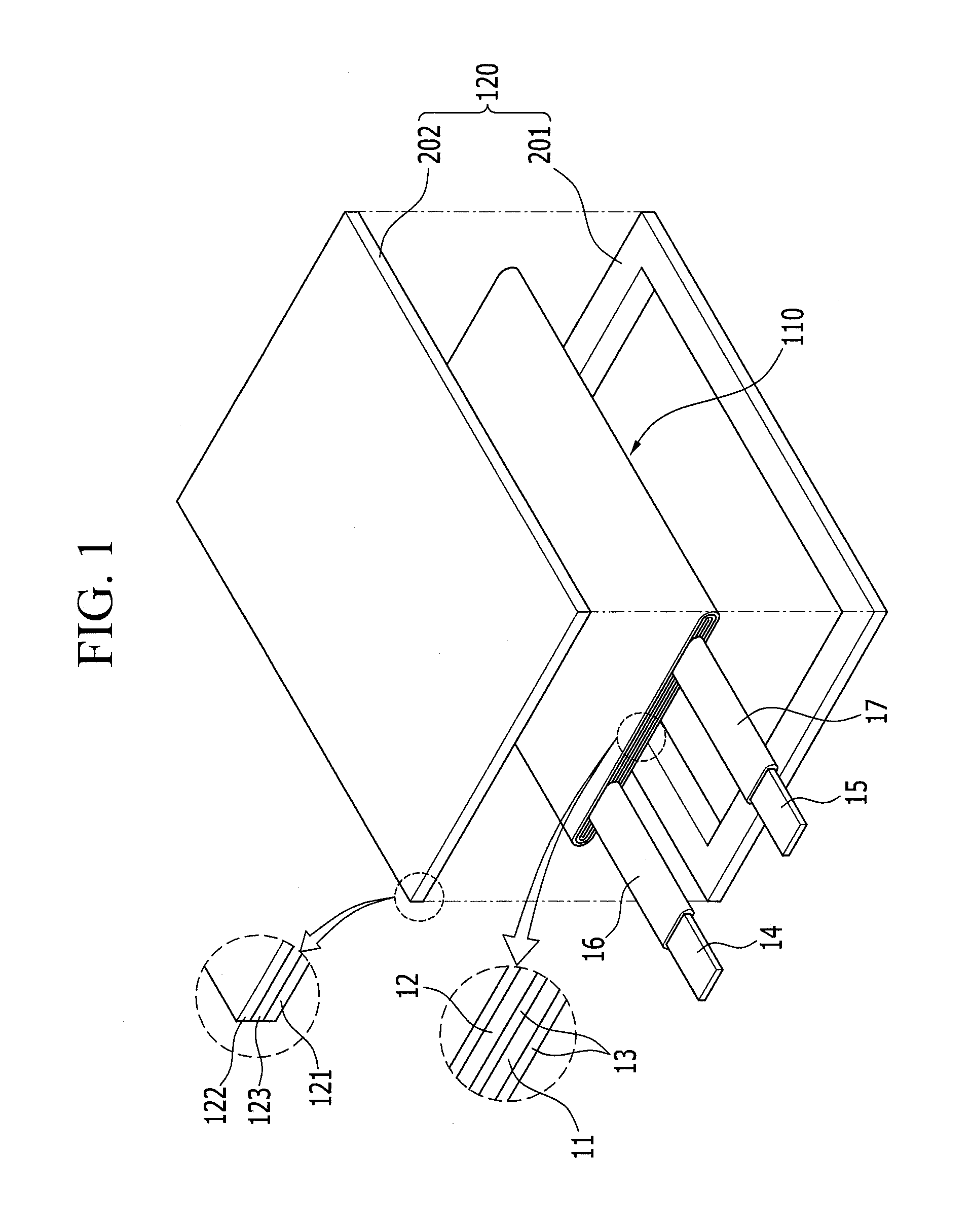
11: first electrode (positive electrode) 11a, 12a: coated region 11b, 12b: uncoated region 12: second electrode (negative electrode) 13: separator 14: first electrode terminal (positive electrode terminal) 15: second electrode terminal (negative electrode terminal) 16, 17: insulating member 110: electrode assembly 111a, 121a: inner coated region 111b: inner uncoated region 112a, 122a: outer coated region 112b, 121b: outer uncoated region 113a, 114a: double-sided (inner and outer side) coated region 113b, 114b: double-sided uncoated 120: case (pouch) region 121: polymer sheet 122: nylon sheet 122b: inner uncoated region of front end portion 123a: additional inner coated region 123b: outer uncoated region of front 123: metal sheet end portion 124a: additional outer coated region 201: first exterior member 202: second exterior member L1, L2, L3: first, second, third length t1, t2, t3: thickness W: width of electrode assembly