COMPRESSED AIR ENERGY STORAGE SYSTEM UTILIZING TWO-PHASE FLOW TO FACILITATE HEAT EXCHANGE
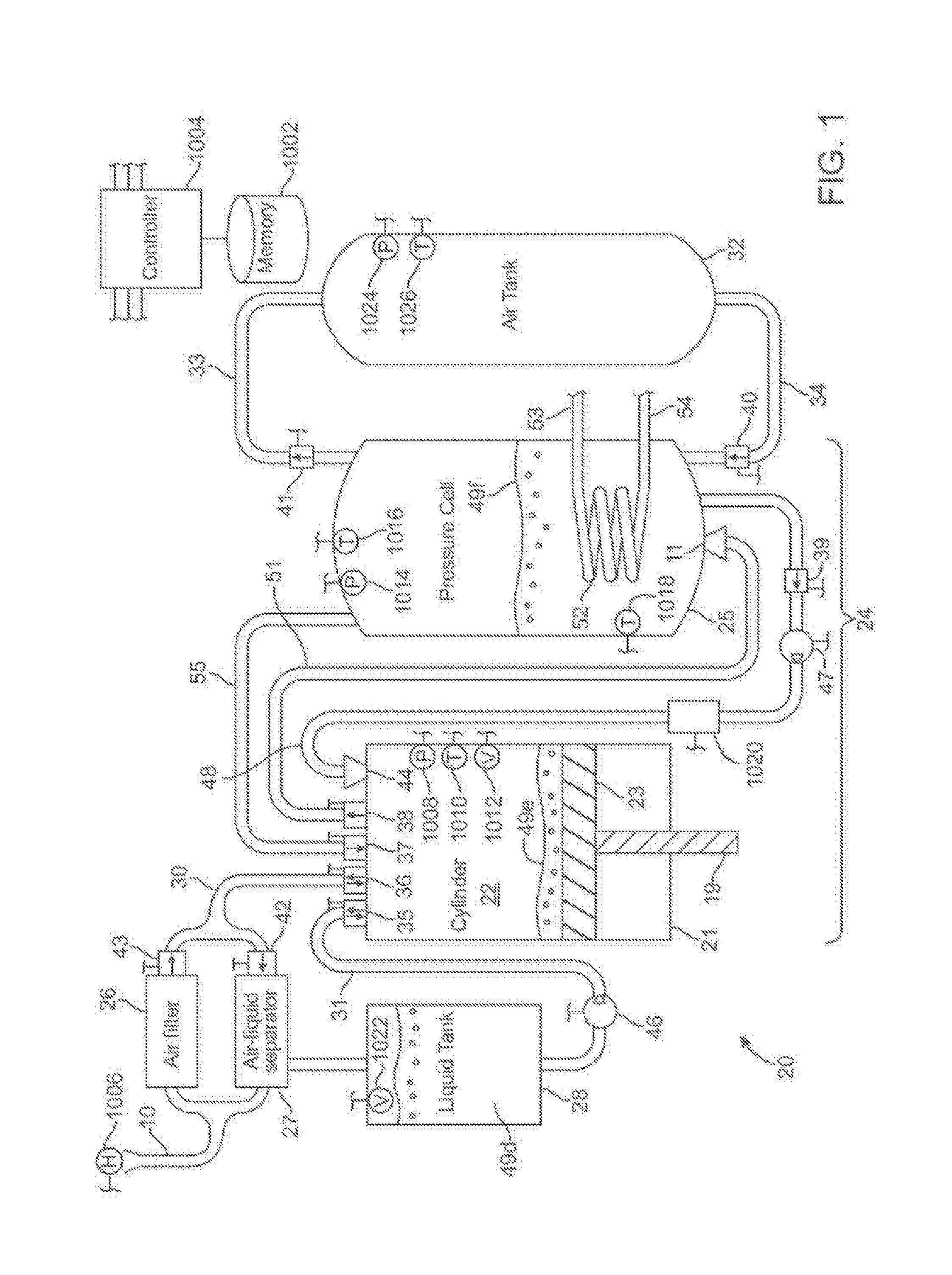
The instant nonprovisional patent application claims priority to and is a continuation of U.S. Nonprovisional patent application Ser. No. 13/952,440 filed Jul. 26, 2013, which claims priority to and is a continuation of U.S. Nonprovisional patent application Ser. No. 13/355,455 filed Jan. 20, 2012, now U.S. Pat. No. 8,516,810 issued on Aug. 27, 2013, which claims priority to and is a continuation U.S. Nonprovisional patent application Ser. No. 12/701,146 filed Feb. 5, 2010, now U.S. Pat. No. 8,182,240 issued on May 22, 2012, which claims priority to and is a continuation of U.S. Nonprovisional patent application Ser. No. 12/695,922 filed Jan. 28, 2010, now U.S. Pat. No. 8,146,354 issued on Apr. 3, 2012, which claims priority to and is a nonprovisional of U.S. Provisional Patent Application No. 61/221,487 filed Jun. 29, 2009, and incorporated by reference in its entirety herein for all purposes. Air compressed to 300 bar has energy density comparable to that of lead-acid batteries and other energy storage technologies. However, the process of compressing and decompressing the air typically is inefficient due to thermal and mechanical losses. Such inefficiency limits the economic viability of compressed air for energy storage applications, despite its obvious advantages. It is well known that a compressor will be more efficient if the compression process occurs isothermally, which requires cooling of the air before or during compression. Patents for isothermal gas compressors have been issued on a regular basis since 1930 (e.g., U.S. Pat. No. 1,751,537 and No. 1,929,350). One approach to compressing air efficiently is to effect the compression in several stages, each stage comprising a reciprocating piston in a cylinder device with an intercooler between stages (e.g., U.S. Pat. No. 5,195,874). Cooling of the air can also be achieved by injecting a liquid, such as mineral oil, refrigerant, or water into the compression chamber or into the airstream between stages (e.g., U.S. Pat. No. 5,076,067). Several patents exist for energy storage systems that mix compressed air with natural gas and feed the mixture to a combustion turbine, thereby increasing the power output of the turbine (e.g., U.S. Pat. No. 5,634,340). The air is compressed by an electrically-driven air compressor that operates at periods of low electricity demand. The compressed-air enhanced combustion turbine runs a generator at times of peak demand. Two such systems have been built, and others proposed, that use underground caverns to store the compressed air. Patents have been issued for improved versions of this energy storage scheme that apply a saturator upstream of the combustion turbine to warm and humidify the incoming air, thereby improving the efficiency of the system (e.g., U.S. Pat. No. 5,491,969). Other patents have been issued that mention the possibility of using low-grade heat (such as waste heat from some other process) to warm the air prior to expansion, also improving efficiency (e.g., U.S. Pat. No. 5,537,822). Embodiments of the present invention relate generally to energy storage systems, and more particularly, relates to energy storage systems that utilize compressed air as the energy storage medium, comprising an air compression/expansion mechanism, a heat exchanger, and one or more air storage tanks. According to embodiments of the present invention, a compressed-air energy storage system is provided comprising a reversible mechanism to compress and expand air, one or more compressed air storage tanks, a control system, one or more heat exchangers, and, in certain embodiments of the invention, a motor-generator. The reversible air compressor-expander uses mechanical power to compress air (when it is acting as a compressor) and converts the energy stored in compressed air to mechanical power (when it is acting as an expander). The compressor-expander comprises one or more stages, each stage consisting of pressure vessel (the “pressure cell”) partially filled with water or other liquid. In some embodiments, the pressure vessel communicates with one or more cylinder devices to exchange air and liquid with the cylinder chamber(s) thereof. Suitable valving allows air to enter and leave the pressure cell and cylinder device, if present, under electronic control. The cylinder device referred to above may be constructed in one of several ways. In one specific embodiment, it can have a piston connected to a piston rod, so that mechanical power coming in or out of the cylinder device is transmitted by this piston rod. In another configuration, the cylinder device can contain hydraulic liquid, in which case the liquid is driven by the pressure of the expanding air, transmitting power out of the cylinder device in that way. In such a configuration, the hydraulic liquid can interact with the air directly, or a diaphragm across the diameter of the cylinder device can separate the air from the liquid. In low-pressure stages, liquid is pumped through an atomizing nozzle into the pressure cell or, in certain embodiments, the cylinder device during the expansion or compression stroke to facilitate heat exchange. The amount of liquid entering the chamber is sufficient to absorb (during compression) or release (during expansion) all the heat associated with the compression or expansion process, allowing those processes to proceed near-isothermally. This liquid is then returned to the pressure cell during the non-power phase of the stroke, where it can exchange heat with the external environment via a conventional heat exchanger. This allows the compression or expansion to occur at high efficiency. Operation of embodiments according the present invention may be characterized by a magnitude of temperature change of the gas being compressed or expanded. According to one embodiment, during a compression cycle the gas may experience an increase in temperate of 100 degrees Celsius or less, or a temperature increase of 60 degrees Celsius or less. In some embodiments, during an expansion cycle, the gas may experience a decrease in temperature of 100 degrees Celsius or less, 15 degrees Celsius or less, or 11 degrees Celsius or less—nearing the freezing point of water from an initial point of room temperature. Instead of injecting liquid via a nozzle, as described above, air may be bubbled though a quantity of liquid in one or more of the cylinder devices in order to facilitate heat exchange. This approach is preferred at high pressures. During expansion, the valve timing is controlled electronically so that only so much air as is required to expand by the desired expansion ratio is admitted to the cylinder device. This volume changes as the storage tank depletes, so that the valve timing must be adjusted dynamically. The volume of the cylinder chambers (if present) and pressure cells increases from the high to low pressure stages. In other specific embodiments of the invention, rather than having cylinder chambers of different volumes, a plurality of cylinder devices is provided with chambers of the same volume are used, their total volume equating to the required larger volume. During compression, a motor or other source of shaft torque drives the pistons or creates the hydraulic pressure via a pump which compresses the air in the cylinder device. During expansion, the reverse is true. Expanding air drives the piston or hydraulic liquid, sending mechanical power out of the system. This mechanical power can be converted to or from electrical power using a conventional motor-generator. While certain drawings and systems depicted herein may be configured using standard symbols, the drawings have been prepared in a more general manner to reflect the variety of implementations that may be realized from different embodiments. While the present invention will be described with reference to a few specific embodiments, the description is illustrative of the invention and is not to be construed as limiting the invention. Various modifications to the present invention can be made to the preferred embodiments by those skilled in the art without departing from the true spirit and scope of the invention. It will be noted here that for a better understanding, like components are designated by like reference numerals throughout the various figures. Single-Stage System As best shown in Briefly, atmospheric air enters the system via pipe 10, passes through the filter 26 and enters the cylinder chamber 22 of cylinder device 21, via pipe 30, where it is compressed by the action of piston 23, by hydraulic pressure, or by other mechanical approaches (see The compressed air/liquid mixture is then transferred into the pressure cell 25 through outlet nozzle 11, via pipe 51. In the pressure cell 25, the transferred mixture exchanges the captured heat generated by compression to a body of liquid 49 The expansion cycle is essentially the reverse process of the compression cycle. Air leaves the air storage tank 32, via pipe 34, bubbling up through the liquid 49 The liquid 49 The apparatus of As described in detail below, based upon input received from one or more system elements, and also possibly values calculated from those inputs, controller/processor 4 may dynamically control operation of the system to achieve one or more objectives, including but not limited to maximized or controlled efficiency of conversion of stored energy into useful work; maximized, minimized, or controlled power output; an expected power output; an expected output speed of a rotating shaft in communication with the piston; an expected output torque of a rotating shaft in communication with the piston; an expected input speed of a rotating shaft in communication with the piston; an expected input torque of a rotating shaft in communication with the piston; a maximum output speed of a rotating shaft in communication with the piston; a maximum output torque of a rotating shaft in communication with the piston; a minimum output speed of a rotating shaft in communication with the piston; a minimum output torque of a rotating shaft in communication with the piston; a maximum input speed of a rotating shaft in communication with the piston; a maximum input torque of a rotating shaft in communication with the piston; a minimum input speed of a rotating shaft in communication with the piston; a minimum input torque of a rotating shaft in communication with the piston; or a maximum expected temperature difference of air at each stage. The compression cycle for this single-stage system proceeds as follows: During step 1 of the compression cycle, liquid 49 During step 2 of the compression cycle, liquid mist from pressure cell 25 is pumped, via pump 47, into the cylinder chamber 22, via pipe 48 and nozzle 44. The selected quantity of mist is sufficient to absorb the heat generated during the compression step (step 3). The volume fraction of liquid must sufficiently low enough that the droplets will not substantially fuse together, thus reducing the effective surface area available for heat exchange (that is, the interface between air and liquid). Typically, the pressure differential between the pressure cell 25 and the chamber 22 of the cylinder device 21 is sufficiently high so that the operation of pump 47 is not required. During step 3 of the compression cycle, the piston 23 is driven upward by a crankshaft (not shown) coupled to a piston rod 19, by hydraulic pressure, or by some other mechanical structure (as shown in Step 4 of the compression cycle begins when the air pressure inside the cylinder chamber 22 is substantially equal to the pressure inside the pressure cell 25, at which point outlet valve 38 opens, allowing compressed air to flow from the cylinder chamber to the pressure cell. Because of the liquid added to the cylinder device during step 1 of the compression cycle, substantially all the air in the cylinder chamber can be pushed out during this step. The compressed air is introduced into the pressure cell 25 through an inlet nozzle 11, along with any entrained mist, creating fine bubbles so that the heat generated during compression will exchange with the liquid 49 During step 5 of the compression cycle, the piston 23 is pulled down allowing low-pressure air to refill it, via valve 36 and pipe 30. The above table shows valve 39 as being closed during this step, and shows pump 47 as being off during this step 5. However, this is not required. In other embodiments valve 39 could be open and pump 47 could be on, during the step 5 such that mist is introduced into the cylinder chamber as it is refilled with air. The expansion cycle for this single-stage system proceeds as follows: During step 1 of the expansion cycle, liquid is added to the cylinder chamber from the liquid tank 28 to eliminate dead volume in the system. This will be required only rarely, as mentioned above. Similar to the compression cycle, the pump 46 can be eliminated if the liquid tank 28 is oriented at an elevation higher than that of the chamber of cylinder device 21. During step 2 of the expansion cycle, a pre-determined amount of air, V0, is added to the chamber of the cylinder device by opening inlet valve 37 for the correct interval, which is dependent on the pressure of the air in the pressure cell and the desired expansion ratio. The V0required is the total cylinder device volume divided by the desired expansion ratio. For a single stage system, that ratio is less than or equal to the pressure of air in the air storage tank in atmospheres. At the same time air is being introduced into the cylinder chamber 22, liquid mist from the pressure cell is being pumped (via pump 47) through inlet nozzle 44 into the cylinder chamber. If a sufficient pressure differential exists between the pressure cell 25 and the cylinder device 21, pump 47 is not required. Once the pressure inside of the cylinder chamber is sufficiently high, valve 37 is closed. The piston 23 is urged in the direction of BDC beginning with this step, transmitting power out of the system via a crankshaft, hydraulic pressure, or other mechanical structure. During step 3 of the expansion cycle, the air introduced in step 2 is allowed to expand in the chamber 22. Liquid mist also continues to be pumped into the chamber 22 through nozzle 44. The predetermined total amount of mist introduced is that required to add enough heat to the system to keep the temperature substantially constant during air expansion. The piston 23 is driven to the bottom of the cylinder device during this step. It will be appreciated that this two-step expansion process (a quantity of air V0introduced in the first step—step 2—and then allowed to expand in the second step—step 3) allows the system to extract substantially all the energy available in the compressed air. During step 4 of the expansion cycle, the crankshaft or other mechanical linkage moves the piston 19 back up to top dead-center (TDC), exhausting the spent air and liquid mist from the cylinder device. The power required to drive the piston comes from the momentum of the system and/or from the motion of other out-of-phase pistons. The exhausted air passes through an air-liquid separator, and the liquid that is separated out is returned to the liquid tank 28. It will be appreciated that in accordance with the present invention, at any given time, energy is either being stored or delivered. The two processes are never carried out simultaneously. As a result, the same mechanism can be used for both compression and expansion, reducing system cost, size and complexity. This is also the situation with all of the other embodiments of the present invention to be described below. Multi-Stage System When a larger compression/expansion ratio is required than can be accommodated by the mechanical or hydraulic approach by which mechanical power is conveyed to and from the system, then multiple stages should be utilized. A multi-stage compressed air energy storage system 20 with three stages (i.e., first stage 24 In accordance with the present invention, each stage may typically have substantially the same expansion ratio. A stage's expansion ratio, r1, is the Nth root of the overall expansion ratio. That is, Where R is the overall expansion ratio and N is the number of stages. It will be appreciated, however, that the different stages can have different expansion ratios, so long as the product of the expansion ratios of all of the stages is R. That is, in a three-stage system, for example: In order for the mass flow rate through each stage to be substantially the, the lower pressure stages will need to have cylinder chambers with greater displacements. In a multi-stage system, the relative displacements of the cylinder chambers are governed by the following equation: Where Viis the volume of the ithcylinder device, and Vfis the total displacement of the system (that is, the sum of the displacements of all of the cylinder devices). As an example, suppose that the total displacement of a three-stage system is one liter. If the stroke length of each piston is substantially the same and substantially equal to the bore (diameter) of the final cylinder chamber, then the volumes of the three cylinder chambers are about 19 cm3, 127 cm3, and 854 cm3. The bores are about 1.54 cm, 3.96 cm, and 10.3 cm, with a stroke length of about 10.3 cm for all three. The lowest-pressure cylinder device is the largest and the highest-pressure cylinder device the smallest. The chambers of the air-driven cylinder devices 21 Stages Using Liquid Mist to Effect Heat Exchange in a Multi-Stage System If a stage is single-acting and uses liquid mist to effect heat exchange, it operates according to the scheme described in the section titled Single-Stage System above. Each single-acting stage of a multi-stage system 20 (e.g., the second stage 24 In contrast, air passes from pressure cell 25 If the stage illustrated is the lowest-pressure-stage (e.g., first stage 24 Single-Acting Stage Utilizing Bubbles to Effect Heat Exchange Instead of using liquid mist sprayed into the cylinder device or pressure cell in order to cool the air as it compresses or warm it as it expands, one specific embodiment of the present invention utilizes the inverse process. As best illustrated in As described above in connection with In contrast, the expansion cycle for this single-acting stage system uses the following process: An air-liquid mixture from the chamber 22 In contrast, air from the pressure cell 25 It will be appreciated that, in some multi-stage systems, some (lower-pressure) stages might employ the liquid mist technique while other (higher-pressure) stages may employ the bubbles technique to store and remove energy therefrom. Multiple Phases The systems as described so far represent a single phase embodiment. That is, all pistons operate together over the course of one cycle. During expansion, for example, this produces a varying amount of mechanical work output during one half of the cycle and requires some work input during the other half of the cycle. Such work input may be facilitated by the use of a flywheel (not shown). To smooth out the power output over the course of one cycle and reduce the flywheel requirements, in one embodiment, multiple systems phases may be employed. N sets of pistons thus may be operated 360/N degrees apart. For example, four complete sets of pistons may be operated 90 degrees out of phase, smoothing the output power and effecting self-starting and a preferential direction of operation. Note that valves connecting cylinder devices to a pressure cell are only opened during less than one-half of a cycle, so it is possible to share a pressure cell between two phases 180 degrees apart. If N phases are used, and N is even, pairs of phases are 180 degrees apart and may be implemented using double-acting pistons. As described above in connection with The compression cycle for the double-acting stage illustrated in In contrast, the expansion cycle for the double-acting stage illustrated in Stages with Multiple Cylinder Devices If it is desirable that all the cylinder devices in a multi-stage system 20 be of substantially similar size, the larger (lower-pressure) cylinder devices may be divided up into two or more smaller cylinder devices communicating in parallel. An example of such a stage is illustrated in Referring back to the embodiment of Multi-cylinder device stages may be single or double-acting, and may use either liquid mist or bubbles to effect heat exchange. A multi-stage system may have some stages with a single cylinder device and others with multiple cylinder devices. Options for Conveying Mechanical Power to and from the System At least four methods may be applied to convey power to and from a stage in accordance with the present invention. These are described as follows, and illustrated in W. A direct-acting hydraulic cylinder device 21 X. A single-acting piston 23 Y. A double-acting piston (also illustrated in Z. A hydraulic cylinder device 21 with a diaphragm 125 is illustrated such that when air enters the cylinder chamber 22 Note that all four of these options can be used with either the liquid mist technique or the bubbles technique to effect heat transfer. The necessary valves and nozzles to supply the mist or bubbles are not shown on While the above examples describe the use of pistons, other types of moveable elements may be utilized and still remain within the scope of the present invention. Examples of alternative types of apparatuses which could be utilized include but are not limited to screw compressors, multi-lobe blowers, vane compressors, gerotors, and quasi-turbines. Single-Stage, Single-Acting Energy Storage System: Referring now to the embodiment of As described above in connection with The compression cycle of the single-stage, single-acting energy storage system 20 proceeds as follows: During step 1, fluid is pumped from pressure cell 25 When all the air has been driven out of cell 25 The expansion cycle of the single-stage, single-acting energy storage system proceeds as follows: In step 1, compressed air is bubbled into pressure cell 25 In step 2, the valve 133 admitting the compressed air into cell 25 As fluid passes through the hydraulic motor 57 during steps 1, 2, and 3, it continues through pipe 139 Steps 4, 5, and 6 mirror steps 1, 2, and 3. That is, compressed air is bubbled into pressure cell 25 If reservoir 13 Over time, both liquid traps 13 The volume of compressed air bubbled into the cells during steps 1 and 3 depends on the power output desired. If the air can expand fully to one atmosphere without displacing all the liquid in the cell, then the maximum amount of work will be done during the stroke. If the air does not fully expand during the stroke, all else being equal the power output will be higher at the expense of efficiency. Note that the pressure cells cannot be of insufficient height so that the air bubbles reach the surface of the liquid during the course of the stroke, since almost all heat exchange with the body of liquid occurs while the bubbles are rising through it. However, they must be sufficiently tall for the column of bubbles to completely separate from the fluid by the time the exhaust stroke completes. If the system must be run slowly, some of the bubbles will reach the top before expansion completes. In this event, liquid mist is sprayed through nozzles 141 (in step 3) or 142 (in step 6) of the expansion cycle. System Configurations It will be understood that a plurality of energy storage system embodiments, designed in accordance with this invention, are possible. These energy storage systems 20 may be single or multi-stage. Stages may be single-cylinder device or multi-cylinder device. Heat exchange may be effected via liquid mist or via bubbles. Power may be conveyed in and out of the system via any of the at least four methods described in the previous section. Each possible configuration has advantages for a specific application or set of design priorities. It would not be practicable to describe every one of these configurations here, but it is intended that the information given should be sufficient for one practiced in the art to configure any of these possible energy storage systems as required. All of the many possible configurations have three elements in common: 1. Near-isothermal expansion and compression of air, with the required heat exchange effected by a liquid phase in high-surface-area contact with the air. 2. A reversible mechanism capable of both compression and expansion of air. 3. Electronic control of valve timing so as to obtain the highest possible work output from a given volume of compressed air. Note that all the configurations described herein use and generate power in mechanical form, be it hydraulic pressure or the reciprocating action of a piston. In most applications, however, the requirement will be for the storage of electrical energy. In that case, a generator, along with appropriate power conditioning electronics, must be added to convert the mechanical power supplied by the system during expansion to electrical power. Similarly, the mechanical power required by the system during compression must be supplied by a motor. Since compression and expansion are never done simultaneously, a motor-generator may be used to perform both functions. If the energy storage system utilizes a hydraulic motor or a hydro turbine, then the shaft of that device connects directly or via a gearbox to the motor-generator. If the energy storage system utilizes reciprocating pistons, then a crankshaft or other mechanical linkage that can convert reciprocating motion to shaft torque is required. Use of Waste Heat During Expansion In order to operate isothermally, the tendency of air to cool as it expands while doing work (i.e. by pushing a piston or displacing hydraulic liquid) must be counteracted by heat exchange with the ambient air or with a body of water (e.g. a stream or lake). If, however, some other source of heat is available—for example, hot water from a steam condenser—it may be used advantageously during the expansion cycle. In Because the system operates substantially at or near ambient temperature, the source of heat need only be a few degrees above ambient in order to be useful in this regard. The heat source must, however, have sufficient thermal mass to supply all the heat required to keep the expansion process at or above ambient temperature throughout the cycle. As described in detail above, embodiments of systems and methods for storing and recovering energy according to the present invention are particularly suited for implementation in conjunction with a host computer including a processor and a computer-readable storage medium. Such a processor and computer-readable storage medium may be embedded in the apparatus, and/or may be controlled or monitored through external input/output devices. As noted, mouse 2170 can have one or more buttons such as buttons 2180. Cabinet 2140 houses familiar computer components such as disk drives, a processor, storage device, etc. Storage devices include, but are not limited to, disk drives, magnetic tape, solid-state memory, bubble memory, etc. Cabinet 2140 can include additional hardware such as input/output (I/O) interface cards for connecting computer system 2110 to external devices external storage, other computers or additional peripherals, further described below. An example of such an operational parameter that may be controlled is the timing of opening and closing of a valve allowing the inlet of air to the cylinder during an expansion cycle. Specifically, during step 2 of the expansion cycle, a pre-determined amount of air V0, is added to the chamber from the pressure cell, by opening valve 37 for a controlled interval of time. This amount of air V0is calculated such that when the piston reaches the end of the expansion stroke, a desired pressure within the chamber will be achieved. In certain cases, this desired pressure will approximately equal that of the next lower pressure stage, or atmospheric pressure if the stage is the lowest pressure stage or is the only stage. Thus at the end of the expansion stroke, the energy in the initial air volume V0has been fully expended, and little or no energy is wasted in moving that expanded air to the next lower pressure stage. To achieve this goal, valve 37 is opened only for so long as to allow the desired amount of air (V0) to enter the chamber, and thereafter in steps 3-4 ( In other embodiments, the controller/processor may control valve 37 to cause it to admit an initial volume of air that is greater than V0. Such instructions may be given, for example, when greater power is desired from a given expansion cycle, at the expense of efficiency of energy recovery. Timing of opening and closing of valves may also be carefully controlled during compression. For example, as shown in In conventional compressor apparatuses, accumulated compressed air is contained within the vessel by a check valve, that is designed to mechanically open in response to a threshold pressure. Such use of the energy of the compressed air to actuate a check valve, detracts from the efficiency of recovery of energy from the air for performing useful work. By contrast, as shown in While the timing of operation of valves 37 and 38 of the single stage apparatus may be controlled as described above, it should be appreciated that valves in other embodiments may be similarly controlled. Examples of such valves include but are not limited to valves 130, 132, 133, 134, 136, and 137 of Another example of a system parameter that can be controlled by the processor, is the amount of liquid introduced into the chamber. Based upon one or more values such as pressure, humidity, calculated efficiency, and others, an amount of liquid that is introduced into the chamber during compression or expansion, can be carefully controlled to maintain efficiency of operation. For example, where an amount of air greater than V0is inlet into the chamber during an expansion cycle, additional liquid may need to be introduced in order to maintain the temperature of that expanding air within a desired temperature range. The present invention is not limited to those particular embodiments described above. Other methods and apparatuses may fall within the scope of the invention. For example, the step of adding liquid to a cylinder device is not required during every cycle. In addition, liquid may be added to the chamber at the same time air is being inlet. Accordingly, the following table describes steps in an embodiment of a compression cycle for a single-stage system utilizing liquid mist to effect heat exchange, as shown in connection with The corresponding expansion cycle where liquid is introduced at the same time as air, is shown in the table below, in connection with Moreover, where bubbles are utilized to effect heat exchange, the step of replenishing liquid is not required in every cycle. The following table, in conjunction with The corresponding expansion cycle for this system is shown in the table below in conjunction with Shown in The corresponding expansion cycle for the double-acting stage is illustrated in A compression cycle for a single-stage, single-acting energy storage system shown in The corresponding expansion cycle of the single-stage, single-acting energy storage system proceeds as follows as shown in Variations on the specific embodiments describe above, are possible. For example, in some embodiments, a plurality of pistons may be in communication with a common chamber. In other embodiments, a multistage apparatus may not include a separate pressure cell. For example, in the embodiment of The timing is controlled so the pressures on either side of heat exchanger 10024 are substantially the same when valves 37 and 10058 are open. Liquid for spray nozzle 44 is supplied from an excess water in cylinder 22 by opening valve 10036 and turning on pump 10032. Similarly, liquid for spray nozzle 10064 is supplied from an excess water in cylinder 10046 by opening valve 10038 and turning on pump 10034. Such precise timing during operation may be achieved with the operation of a controller/processor that is communication with a plurality of the system elements, as has been previously described. The present invention is not limited to the embodiments specifically described above. For example, while water has been described as the liquid that is injected into air as a mist, other liquids could be utilized and fall within the scope of the present invention. Examples of liquids that could be used include polypropylene glycol, polyethylene glycol, and alcohols. The following claims relate to compression. 1. A method for storing energy, the method comprising: introducing a first quantity of air at a first temperature into a first chamber;
2. The method of claim 1 wherein the first determined quantity of fluid is based upon one or more control parameters. 3. The method of claim 2 wherein the control parameter is calculated for the compression cycle from a measured physical property. 4. The method of claim 2 wherein the control parameter comprises a maximum increase in a temperature of the first quantity of air during compression. 5. The method of claim 2 wherein the control parameter comprises an amount of the fluid present in liquid form inside the chamber. 6. The method of claim 2 wherein the control parameter comprises an efficiency. 7. The method of claim 2 wherein the control parameter comprises a power input to the piston. 8. The method of claim 2 wherein the control parameter comprises a speed of the piston. 9. The method of claim 2 wherein the control parameter comprises a force on the piston. 10. The method of claim 1 wherein the piston is solid, liquid, or a combination of solid and liquid. 11. The method of claim 1 wherein the first temperature range is reflected by a change in a temperature of the first quantity of air from a first temperature to a second temperature below a boiling point of the fluid. 12. The method of claim 11 wherein the fluid comprises water. 13. The method of claim 12 wherein the first temperature range is about 60 degrees Celsius or less. 14. The method of claim 1 wherein the first determined quantity of fluid is injected by spraying or misting. 15. The method of claim 1 wherein the thermal energy transferred from the first quantity of air to the first determined quantity of fluid is facilitated by bubbling air through a liquid. 16. The method of claim 1 further comprising transferring compressed air within the pressure cell to a storage tank. The following claims relate to compression and expansion. 17. The method of claim 1 further comprising: in an expansion cycle, transferring a second quantity of air from the first pressure cell to the first chamber;
18. The method of claim 17 further comprising generating electrical power from the driving of the first piston. 19. The method of claim 17 wherein the second determined quantity of fluid is based upon one or more control parameters. 20. The method of claim 17 wherein the control parameter is calculated for the expansion cycle from a measured physical property. 21. The method of claim 17 wherein the control parameter comprises a maximum decrease in a temperature of the second quantity of air during the expansion. 22. The method of claim 17 wherein the control parameter comprises an amount of the fluid present in liquid form inside the chamber. 23. The method of claim 17 wherein the control parameter comprises an efficiency. 24. The method of claim 17 wherein the control parameter comprises a power output by the first piston. 25. The method of claim 17 wherein the control parameter comprises a speed of the piston. 26. The method of claim 17 wherein the control parameter comprises a force on the piston. 27. The method of claim 17 wherein the first determined quantity of fluid is injected by spraying or misting. 28. The method of claim 17 wherein thermal energy is transferred from the second quantity of air to the second determined quantity of fluid facilitated by bubbling air through a liquid. 29. The method of claim 17 wherein the fluid comprises water. 30. The method of claim 17 further comprising placing the chamber in communication with additional thermal energy during the expansion cycle. 31. The method of claim 30 wherein the additional thermal energy is waste heat from another thermal source. 32. The method of claim 17 wherein the second temperature range is reflected by a change in a temperature of the second quantity of air from a first temperature to a second temperature above a freezing point of the fluid. 33. The method of claim 32 wherein the fluid comprises water. 34. The method of claim 33 wherein the second temperature range is about 11 degrees Celsius or less. 34a. The method of claim 17 wherein at an end of an expansion stroke of the first piston, the second quantity of air is configured to produce a pressure on the first piston substantially equal to a desired pressure. 34b. The method of claim 34a, wherein the desired pressure is an input pressure of the next lowest pressure stage, or is ambient pressure. 34c. The method of claim 34a wherein the desired pressure is calculated to maximize an efficiency of expansion. 34d. The method of claim 34a wherein the desired pressure is calculated to produce a desired level of power output. 34e. The method of claim 34a wherein the desired pressure is within approximately 5 psi of an input pressure of the next lowest pressure stage. The following claims relate to multi-stage operation. 35. The method of claim 17 further comprising: providing a second chamber in selective fluid communication with the first pressure cell and with a second pressure cell;
36. The method of claim 35 further comprising: in an expansion cycle of the second chamber, transferring a fourth quantity of air from the second pressure cell to the second chamber;
The following claims relate to expansion. 37. A method for releasing stored energy, the method comprising: in an expansion cycle, transferring a quantity of air from a pressure cell to a chamber having a piston disposed therein;
38. The method of claim 37 wherein the determined quantity of fluid is based upon one or more control parameters. 39. The method of claim 38 wherein the control parameter is calculated from a measured physical property. 40. The method of claim 38 wherein the control parameter comprises a maximum decrease in a temperature of the quantity of air during the expansion. 41. The method of claim 38 wherein the control parameter comprises an amount of the fluid present in liquid form inside the chamber. 42. The method of claim 38 wherein the control parameter comprises an efficiency. 43. The method of claim 38 wherein the control parameter comprises a power input to the piston. 44. The method of claim 38 wherein the control parameter comprises a speed of the piston. 45. The method of claim 38 wherein the control parameter comprises a force of the piston. 46. The method of claim 38 wherein the piston is solid, liquid, or a combination of solid and liquid. 47. The method of claim 38 wherein the fluid comprises water. 48. The method of claim 38 wherein the first temperature range is reflected by a change in a temperature of the first quantity of air from a first temperature to a second temperature, the change less than a determined value. 49. The method of claim 48 wherein the lower temperature is greater than a freezing point of the fluid. 50. The method of claim 48 wherein the higher temperature is less than a boiling point of the fluid. 51. The method of claim 38 wherein the first determined quantity of fluid is injected by spraying or misting. 52. The method of claim 38 wherein the thermal energy transferred from the quantity of air to the determined quantity of fluid is facilitated by bubbling air through a liquid. 52a. The method of claim 37 wherein at an end of an expansion stroke of the piston, the quantity of air is configured to produce a pressure on the piston substantially equal to a desired pressure. 52b. The method of claim 37, wherein the desired pressure is an input pressure of the next lowest pressure stage, or is ambient pressure. 52c. The method of claim 37 wherein the desired pressure is calculated to maximize an efficiency of expansion. 52d. The method of claim 37 wherein the desired pressure is calculated to produce a desired level of power output. 52e. The method of claim 37 wherein the desired pressure is within approximately 5 psi of an input pressure of the next lowest pressure stage. The following claims relate to temperature difference during system operation. 53. A method comprising: providing an energy storage system comprising a pressure cell in selective fluid communication with a chamber having a moveable piston disposed therein;
54. The method of claim 53 wherein determining an operational parameter comprises controlling an amount of a liquid introduced into the air within the chamber during the compression cycle. 55. The method of claim 53 wherein the liquid comprises water. 56. The method of claim 53 wherein determining an operational parameter comprises controlling an amount of a liquid introduced into the air within the chamber during the expansion cycle. 57. The method of claim 56 wherein the liquid comprises water. 58. The method of claim 53 wherein a lower bound of the range is greater than a freezing point of a liquid introduced into the air within the chamber. 59. The method of claim 58 wherein the liquid comprises water. 60. The method of claim 53 wherein an upper bound of the range is lower than a boiling point of a liquid introduced into the air within the chamber. 61. The method of claim 60 wherein the liquid comprises water. 62. The method of claim 53 wherein determining an operational parameter comprises controlling a timing of the transfer of air from the pressure cell into the chamber during the expansion cycle. 62a. The method of claim 62 wherein the timing is controlled such that at an end of an expansion stroke of the piston, the transferred air is configured to produce a desired pressure on the piston. 62b. The method of claim 62a, wherein the desired pressure is an input pressure of the next lowest pressure stage, or is ambient pressure. 62c. The method of claim 62a wherein the desired pressure is calculated to maximize an efficiency of expansion. 62d. The method of claim 62a wherein the desired pressure is calculated to produce a desired level of power output. 62e. The method of claim 62a wherein the desired pressure is within approximately 5 psi of an input pressure of the next lowest pressure stage. 63. The method of claim 53 wherein determining an operational parameter comprises monitoring a pressure in the pressure cell. 64. The method of claim 53 wherein determining an operational parameter comprises monitoring a pressure in the chamber. 65. The method of claim 53 wherein determining an operational parameter comprises monitoring a temperature of the air in the chamber. 66. The method of claim 53 wherein determining an operational parameter comprises monitoring a humidity of the air flowed into the chamber. 67. The method of claim 53 wherein determining an operational parameter comprises monitoring a humidity of air exhausted from the chamber. 68. The method of claim 53 wherein determining an operational parameter comprises monitoring a power released during the expansion cycle. 69. The method of claim 53 wherein determining an operational parameter comprises monitoring a position of the piston. 70. The method of claim 53 wherein determining an operational parameter comprises monitoring a force on the piston. 71. The method of claim 54 wherein determining an operational parameter comprises monitoring a temperature of the liquid. 72. The method of claim 56 wherein determining an operational parameter comprises monitoring a temperature of the liquid. 73. The method of claim 54 wherein determining an operational parameter comprises monitoring a rate of flow of the liquid. 74. The method of claim 56 wherein determining an operational parameter comprises monitoring a rate of flow of the liquid. 75. The method of claim 54 wherein determining an operational parameter comprises monitoring a level of the liquid in the chamber. 76. The method of claim 56 wherein determining an operational parameter comprises monitoring a level of the liquid in the chamber. 77. The method of claim 54 wherein determining an operational parameter comprises monitoring a volume of the liquid in the chamber. 78. The method of claim 56 wherein determining an operational parameter comprises monitoring a volume of the liquid in the chamber. 79. The method of claim 53 wherein: the piston is in communication with a rotating shaft; and
80. The method of claim 53 wherein: the piston is in communication with a rotating shaft; and
81. The method of claim 53 wherein the operational parameter is controlled based upon a derived parameter calculated from the monitored operational parameter. 82. The method of claim 81 wherein the derived parameter is selected from the group comprising, an efficiency of power conversion, an expected power output, an expected output speed of a rotating shaft in communication with the piston, an expected output torque of a rotating shaft in communication with the piston, an expected input speed of a rotating shaft in communication with the piston, an expected input torque of a rotating shaft in communication with the piston, a maximum output speed of a rotating shaft in communication with the piston, a maximum output torque of a rotating shaft in communication with the piston, a minimum output speed of a rotating shaft in communication with the piston, a minimum output torque of a rotating shaft in communication with the piston, a maximum input speed of a rotating shaft in communication with the piston, a maximum input torque of a rotating shaft in communication with the piston, a minimum input speed of a rotating shaft in communication with the piston, a minimum input torque of a rotating shaft in communication with the piston, or a maximum expected temperature difference of air at each stage. 83. The method of claim 53 wherein controlling the operational parameter comprises controlling a timing of the transfer of air from the chamber to the pressure cell during the compression cycle. 84. The method of claim 53 wherein controlling the operational parameter comprises controlling a timing of the transfer of air from the pressure cell to the chamber during the expansion cycle. 85. The method of claim 54 wherein controlling the operational parameter comprises controlling a timing of a flow of liquid to the chamber. 86. The method of claim 56 wherein controlling the operational parameter comprises controlling a timing of a flow of liquid to the chamber. 87. The method of claim 53 wherein: during the compression cycle, the piston is in communication with a motor or a motor-generator; and
88. The method of claim 53 wherein: during the expansion cycle, the piston is in communication with a generator or a motor-generator; and
89. The method of claim 54 wherein: the liquid is flowed to the chamber utilizing a pump; and
90. The method of claim 56 wherein: the liquid is flowed to the chamber utilizing a pump; and
91. The method of claim 53 wherein: liquid in the pressure cell is circulated through a heat exchanger that is in thermal communication with a fan; and
92. The method of claim 53 further comprising placing the chamber in communication with additional thermal energy during the expansion cycle. 93. The method of claim 92 wherein the additional thermal energy is waste heat from another thermal source. 94. The method of claim 53 wherein controlling the operational parameter comprises controlling a compression ratio. 95. The method of claim 53 further comprising transferring compressed air within the pressure cell to a storage tank. The following claims relate to a system. 96. An energy storage and recovery system comprising: a first chamber having a moveable piston disposed therein and in selective communication with an energy source;
97. The energy storage and recovery system of claim 96 wherein the moveable piston comprises a solid piston. 98. The energy storage and recovery system of claim 96 wherein the moveable piston comprises a liquid piston. 99. The energy storage and recovery system of claim 96 further comprising a sprayer configured to inject the liquid into the air within the chamber. 100. The energy storage and recovery system of claim 99 wherein the liquid comprises water. 101. The energy storage and recovery system of claim 96 further comprising a bubbler configured to transfer heat between the liquid and air within the pressure cell. 102. The energy storage and recovery system of claim 101 wherein the liquid comprises water. 103. The energy storage and recovery system of claim 96 further comprising a sensor configured to detect a volume of liquid present within the chamber, the sensor in electronic communication with the controller and referenced to determine the operational parameter. 104. The energy storage and recovery system of claim 96 further comprising a sensor configured to detect a property selected from the group comprising, a pressure, a temperature, a humidity, a position of the piston, a force on the piston, a liquid flow rate, a liquid level, a liquid volume, a speed of a shaft driven by the piston, or a torque of the shaft driven by the piston, wherein the sensor is in electronic communication with the controller and referenced to determine the operational parameter. 105. The energy storage and recovery system of claim 96 further comprising a power generator or motor-generator configured to be in selective communication with the piston during the expansion stroke. 106. The energy storage and recovery system of claim 96 wherein the chamber is configured to be in thermal communication with a thermal energy source. 107. The energy storage and recovery system of claim 96 further comprising a storage tank configured to receive compressed air from the pressure cell. 107a. The energy storage and recovery system of claim 96 wherein during the expansion the controller is configured to operate the first valve to inlet the air such that at an end of an expansion stroke of the piston, a pressure on the piston is substantially equal to a desired pressure. 107b. The method of claim 107a, wherein the desired pressure is an input pressure of the next lowest pressure stage, or is ambient pressure. 107c. The method of claim 107a wherein the desired pressure is calculated to maximize an efficiency of expansion. 107d. The method of claim 107a wherein the desired pressure is calculated to produce a desired level of power output. 107e. The method of claim 107a wherein the desired pressure is within approximately 5 psi of an input pressure of the next lowest pressure stage. The following claims relate to a system having multiple stages. 108. The energy storage and recovery system of claim 96, further comprising: a second chamber having a moveable piston disposed therein and in selective communication with the energy source; and
109. The energy storage and recovery system of claim 96, further comprising a plurality of a second chamber and second pressure cell connected in series with the first chamber and first pressure cell, such that output from the first chamber is communicated to the second chamber. The following claims relate to a processor. 110. An apparatus for storing and recovering energy, the apparatus comprising: a host computer comprising a processor in electronic communication with a computer-readable storage medium, the computer readable storage medium having stored thereon one or more codes to instruct the processor to,
111. The apparatus of claim 110 wherein the code stored on the computer readable storage medium is configured to receive the signal indicating a pressure in the pressure cell. 112. The apparatus of claim 110 wherein the code stored on the computer readable storage medium is configured to receive the signal indicating a pressure in the first chamber. 113. The apparatus of claim 110 wherein the code stored on the computer readable storage medium is configured to receive the signal indicating a temperature of the air in the first chamber. 114. The apparatus of claim 110 wherein the code stored on the computer readable storage medium is configured to receive the signal indicating a temperature of the air in the pressure cell. 115. The apparatus of claim 110 wherein the code stored on the computer readable storage medium is configured to receive the signal indicating a humidity of the air inlet to the first chamber. 116. The apparatus of claim 110 wherein the code stored on the computer readable storage medium is configured to receive the signal indicating a power output. 117. The apparatus of claim 110 wherein the code stored on the computer readable storage medium is configured to receive the signal indicating a humidity of the air exhausted from the first chamber. 118. The apparatus of claim 110 wherein the code stored on the computer readable storage medium is configured to receive the signal indicating a position of the piston. 119. The apparatus of claim 110 wherein the code stored on the computer readable storage medium is configured to receive the signal indicating a force on the piston. 120. The apparatus of claim 110 wherein the code stored on the computer readable storage medium is configured to receive the signal indicating a temperature of liquid flowed to the chamber. 121. The apparatus of claim 110 wherein the code stored on the computer readable storage medium is configured to receive the signal indicating rate of flow of liquid to the chamber. 122. The apparatus of claim 110 wherein the code stored on the computer readable storage medium is configured to receive the signal indicating a level of liquid in the chamber. 123. The apparatus of claim 110 wherein the code stored on the computer readable storage medium is configured to receive the signal indicating volume of liquid in the chamber. 124. The apparatus of claim 110 wherein the code stored on the computer readable storage medium is configured to receive the signal indicating a speed of a rotating shaft in communication with the piston. 125. The apparatus of claim 110 wherein the code stored on the computer readable storage medium is configured to receive the signal indicating torque of a rotating shaft in communication with the piston. 126. The apparatus of claim 110 wherein in response to the received signal, the code stored on the computer readable storage medium is configured to instruct the processor to control a timing of a transfer of air from the chamber to the pressure cell during a compression cycle. 126a. The apparatus of claim 110 wherein in response to the received signal, the code stored on the computer readable storage medium is configured to instruct the processor to control a timing of a transfer of air from the pressure cell to the chamber during an expansion cycle. 127. The apparatus of claim 110 wherein in response to the received signal, the code stored on the computer readable storage medium is configured to instruct the processor to control a timing of a transfer of liquid to the chamber. 128. The apparatus of claim 110 wherein in response to the received signal, the code stored on the computer readable storage medium is configured to instruct the processor to control the amount of liquid transferred to the chamber. 129. The apparatus of claim 110 wherein in response to the received signal, the code stored on the computer readable storage medium is configured to instruct the processor to control an electrical load applied to a generator or a motor-generator in communication with the piston, during an expansion cycle. 130. The apparatus of claim 110 wherein in response to the received signal, the code stored on the computer readable storage medium is configured to instruct the processor to control an electrical power applied to a motor or a motor-generator in communication with the piston, during a compression cycle. 131. The apparatus of claim 110 wherein in response to the received signal, the code stored on the computer readable storage medium is configured to instruct the processor to control an electrical power applied to a pump to flow liquid into the chamber. 132. The apparatus of claim 110 wherein in response to the received signal, the code stored on the computer readable storage medium is configured to instruct the processor to control an electrical power applied to fans associated with a heat exchanger configured to receive liquid from the pressure cell. 133. The apparatus of claim 110 wherein in response to the received signal, the code stored on the computer readable storage medium is configured to instruct the processor to control a compression ratio. The following claims relate to a multi-stage system. 134. An energy storage and recovery system comprising: a first stage comprising a first element moveable to compress air in the first stage, the first stage in selective fluid communication with an ambient air supply through a first valve;
135. The energy storage and recovery system of claim 134, wherein the first moveable element is also moveable in response to expanding air within the first stage. 136. The energy storage and recovery system of claim 134, wherein the first moveable element comprises a piston. 137. The energy storage and recovery system of claim 134, wherein the first moveable element comprises a screw. 138. The energy storage and recovery system of claim 134, wherein the first stage or the final stage comprises a pressure cell in selective fluid communication with a chamber. 139. The energy storage and recovery system of claim 134, wherein the first stage is configured to transfer to, and receive compressed air from, the final stage through a third valve. 140. The energy storage and recovery system of claim 139, wherein the first stage comprises a first chamber having a first piston disposed therein as the first moveable element, and the final stage comprises a second chamber having a second piston disposed therein as the second moveable element, the first and final stages lacking a pressure cell. 141. The energy storage and recovery system of claim 134, further comprising an intermediate stage positioned in series and in selective fluid communication between the first stage and the final stage, the intermediate stage comprising a third element moveable to compress air in the intermediate stage, and moveable in response to expanding air within the intermediate stage. 142. The energy storage and recovery system of claim 141, wherein the first moveable element is also moveable in response to expanding air within the first stage. 143. The energy storage and recovery system of claim 142, wherein the first stage comprises a first chamber having a first piston disposed therein as the first moveable element, and the intermediate stage comprises a second chamber having a second piston disposed therein as the third moveable element. 144. The energy storage and recovery system of claim 141, wherein the intermediate stage comprises a first chamber having a first piston disposed therein as the third moveable element, and the final stage comprises a second chamber having a second piston disposed therein as the second moveable element. 145. The energy storage and recovery system of claim 141, wherein the first stage, the intermediate stage, or the final stage comprises a chamber in selective fluid communication with a pressure cell. 146. The energy storage and recovery system of claim 141, wherein consecutive stages do not include a pressure cell. 147. The energy storage and recovery system of claim 141, further comprising additional intermediate stages positioned in series between the first stage and the final stage. 148. The energy storage and recovery system of claim 134, wherein the second moveable element comprises a piston. 149. The energy storage and recovery system of claim 148, wherein the second moveable element comprises a liquid piston. 150. The energy storage and recovery system of claim 148, wherein the second moveable element comprises a solid piston. 151. The energy storage and recovery system of claim 134, wherein a compression ratio of the first stage is larger than a compression ratio of the final stage. 152. The energy storage and recovery system of claim 141, wherein a compression ratio of the first stage is larger than a compression ratio of the intermediate stage, and the compression ratio of the intermediate stage is greater than a compression ratio of the final stage. 153. The energy storage and recovery system of claim 134, wherein the liquid comprises water. 154. A method of storing energy, the method comprising: receiving ambient air in a first stage;
155. The method of claim 154 wherein the determined operational parameter comprises a timing of opening or closing valves controlling movement of air into or out of the stages. 156. The method of claim 154 wherein the determined operational parameter comprises an amount of liquid injected into the first stage or into the final stage during the compression or the further compression. 157. The method of claim 154 wherein compressing the ambient air comprises placing a piston disposed within a chamber of the first stage, in communication with an energy source. 158. The method of claim 154 wherein compressing the ambient air comprises placing a screw disposed within a chamber of the first stage, in communication with an energy source. 159. The method of claim 154 wherein compressed air is transferred to the final stage via an intermediate stage in which additional compression takes place. 160. The method of claim 154 further comprising: transferring compressed air from the storage tank to the final stage;
161. The method of claim 160 wherein the determined operational parameter comprises a timing of opening or closing valves controlling movement of air into or out of the stages. 162. The method of claim 160 wherein the determined operational parameter comprises an amount of liquid injected into the first stage or into the final stage during expansion of air within the first stage or the second stage. 163. The method of claim 160 wherein the first moveable element comprises a piston. 164. The method of claim 160 wherein the second moveable element comprises a piston. 165. The method of claim 160 wherein air is transferred from the final stage to the first stage via an intermediate stage wherein further expansion of air takes place. A compressed-air energy storage system according to embodiments of the present invention comprises a reversible mechanism to compress and expand air, one or more compressed air storage tanks, a control system, one or more heat exchangers, and, in certain embodiments of the invention, a motor-generator. The reversible air compressor-expander uses mechanical power to compress air (when it is acting as a compressor) and converts the energy stored in compressed air to mechanical power (when it is acting as an expander). In certain embodiments, the compressor-expander comprises one or more stages, each stage consisting of pressure vessel (the “pressure cell”) partially filled with water or other liquid. In some embodiments, the pressure vessel communicates with one or more cylinder devices to exchange air and liquid with the cylinder chamber(s) thereof. Suitable valving allows air to enter and leave the pressure cell and cylinder device, if present, under electronic control. 1. A method comprising:
introducing a first quantity of a gas at a first temperature into a first chamber; in a compression cycle, subjecting the first quantity of gas to compression by a first piston coupled to the first chamber; injecting a first determined quantity of liquid into the first quantity of gas to absorb thermal energy generated by the compression cycle and thereby maintain the first quantity of gas in a first temperature range during the compression; and transferring at least a portion of the first quantity of gas to a pressure vessel partially filled with the liquid. 2. The method of 3. The method of 4. The method of 5. The method of 6. The method of 7. The method of 8. The method of 9. The method of 10. The method of 11. The method of 12. The method of 13. The method of 14. The method of 15. The method of 16. The method of 17. The method of 18. The method of 19. The method of 20. The method of CROSS-REFERENCE TO RELATED APPLICATION
BACKGROUND
BRIEF SUMMARY OF THE INVENTION
BRIEF DESCRIPTION OF THE DRAWINGS
DETAILED DESCRIPTION OF THE INVENTION
Step 1 2 3 4 5 Description Move Add liquid Add mist compressed Refill to cylinder to cylinder air to cylinder device device Compress pressure cell device Valve 35 Open Closed Closed Closed Closed Valve 36 Open Closed Closed Closed Open Valve 37 Closed Closed Closed Closed Closed Valve 38 Closed Closed Closed Open Closed Valve 39 Closed Open Closed Closed Closed Valve 40 Closed Closed Closed Closed Closed Valve 41 Closed Closed Closed Open Closed Valve 42 Open Closed Closed Closed Closed Valve 43 Closed Closed Closed Closed Open Pump 46 On Off Off Off Off Pump 47 Off On Off Off Off Piston 23 Near bottom Near BDC At BDC at Between At TDC dead center start of BDC and at start (BDC) step TDC of step Step 1 2 3 4 Description Add compressed air and liquid Add liquid to mist to cylinder Exhaust cylinder device device Expansion spent air Valve 35 Open Closed Closed Closed Valve 36 Open Closed Closed Open Valve 37 Closed Open Closed Closed Valve 38 Closed Closed Closed Closed Valve 39 Closed Open Closed Closed Valve 40 Closed Open Closed Closed Valve 41 Closed Closed Closed Closed Valve 42 Closed Closed Closed Open Valve 43 Closed Closed Closed Closed Pump 46 On Off Off Off Pump 47 Off On Off Off Piston 23 Near TDC At TDC at start Near TDC at At BDC of step start of step at start of step Step 1 2 3 4 Description Fill Transfer cylinder air to device pressure Replenish with air Compress cell liquid Valve 108c Closed Closed Closed Closed Valve 109c Closed Closed Open Closed Valve 114c Closed Closed Closed Closed Valve 41c Closed Closed Open Closed Valve 40c Closed Closed Closed Closed Valve 106c Open Closed Closed Closed Valve 110c Closed Closed Closed Closed Valve 111c Closed Closed Closed Open Pump 105c On Off Off Off Pump 113c Off Off Off On Piston 23c At top At TDC Near At BDC 23c of liquid at start BDC at at start at start of step start of of step of step step Step 1 2 3 4 Description Add Replenish compressed liquid air to in cylinder cylinder Exhaust device device Expansion spent air Valve 108c Closed Closed Closed Open Valve 109c Closed Closed Closed Closed Valve 114c Closed Open Closed Closed Valve 41c Closed Closed Closed Closed Valve 40c Closed Open Closed Closed Valve 106c Closed Closed Closed Closed Valve 110c Open Closed Closed Closed Valve 111c Closed Closed Closed Closed Pump 105c Off Off Off Off Pump 113c On Off Off Off Piston 23c At BDC At top Near At TDC at start of liquid BDC at at start start Step 1 2 3 4 5 Description Add mist to Move air to chamber 22b1 Compress air pressure cell and move air in chamber from chamber Refill chamber Replenish to pressure 22b1 and 22b1 and add 22b1 and liquids in cell from refill chamber mist to compress air in cylinder chamber 22b2 22b2 chamber 22b2 chamber 22b2 device Valve 35b1 Closed Closed Open Open Closed Valve 36b1 Closed Closed Closed Closed Open Valve 37b1 Closed Closed Closed Closed Closed Valve 38b1 Closed Closed Open Closed Closed Valve 39b1 Open Closed Closed Closed Closed Valve 35b2 Open Open Closed Closed Closed Valve 36b2 Closed Closed Closed Closed Open Valve 37b2 Closed Closed Closed Closed Closed Valve 38b2 Open Closed Closed Closed Closed Valve 39b2 Closed Closed Open Closed Closed Valve 40b Closed Closed Closed Closed Closed Valve 41b Open Closed Open Closed Closed Pump 47b On Off On Off Off Piston 23b Near TDC at Between TDC Near BDC at Between TDC Between start of step and BDC, start of step and BDC, TDC and moving down moving up BDC Note that step 5 is unnecessary, in some specific embodiments, and can be omitted in the great majority of cycles since the liquid levels in the piston remain substantially the same across long periods of operation. Step 1 2 3 4 5 Description Allow air in Allow air in Add mist and chamber 22b1 Add mist and chamber 22b2 air to chamber to expand and air to chamber to expand and 22b1 and continue 22b2 and continue Replenish exhaust air exhausting air exhaust air exhausting air liquids in from chamber from chamber from chamber from chamber cylinder 22b2 22b2 22b1 22b1 device Valve 35b1 Closed Closed Open Open Closed Valve 36b1 Closed Closed Closed Closed Open Valve 37b1 Open Closed Closed Closed Closed Valve 38b1 Closed Closed Closed Closed Closed Valve 39b1 Open Closed Closed Closed Closed Valve 35b2 Open Open Closed Closed Closed Valve 36b2 Closed Closed Closed Closed Open Valve 37b2 Closed Closed Open Closed Closed Valve 38b2 Closed Closed Closed Closed Closed Valve 39b2 Closed Closed Open Closed Closed Valve 40b Open Closed Open Closed Closed Valve 41b Closed Closed Closed Closed Closed Pump 47b On Off On Off Off Piston 23b Near TDC at Between TDC Near BDC at Between TDC Between start of step and BDC, start of step and BDC, TDC and moving down moving up BDC Note that, as with compression, step 5 is rarely necessary and can be omitted in the great majority of cycles. Step 1 2 3 4 Description Compress air in Compress air in cell 25d while Move cell 25e while Move spraying mist, compressed air spraying mist, compressed air and replenish the from cell 25d to and replenish the from cell 25e to air in cell 25e air tank air in cell 25d air tank Valve 130 Closed Closed Open Open Valve 131 Open Open Closed Closed Valve 132 Closed Open Closed Closed Valve 133 Closed Closed Closed Closed Valve 134 Open Open Closed Closed Valve 135 Closed Closed Open Open Valve 136 Closed Closed Closed Open Valve 137 Closed Closed Closed Closed Valve 138 Pump out to cell Pump out to Pump out to cell Pump out to cell 25d, pump in cell25d, pump 25e, pump in 25e, pump in from cell 25e in from cell 25e from cell 25d from cell 25d Pump 46 On On On On Step 1 2 3 Description Move Refill compressed cylinder air to device Compress pressure cell Valve 35 Closed Closed Closed Valve 36 Open Closed Closed Valve 37 Closed Closed Closed Valve 38 Closed Closed Open Valve 39 Open Closed Closed Valve 40 Closed Closed Closed Valve 41 Open Open Open Valve 42 Closed Closed Closed Valve 43 Open Closed Closed Pump 46 Off Off Off Pump 47 On Off Off Piston 23 At TDC At BDC Between at start at start BDC and of step of step TDC Step 1 2 3 Description Add compressed air and liquid mist to cylinder Exhaust device Expansion spent air Valve 35 Closed Closed Closed Valve 36 Closed Closed Open Valve 37 Open Closed Closed Valve 38 Closed Closed Closed Valve 39 Open Closed Closed Valve 40 Open Open Open Valve 41 Closed Closed Closed Valve 42 Closed Closed Open Valve 43 Closed Closed Closed Pump 46 Off Off Off Pump 47 On Off Off Piston 23 At TDC at Near TDC at At BDC at start of step start of step start of step Step 1 2 3 Description Fill cylinder device Transfer air to with air Compress pressure cell Valve 108c Closed Closed Closed Valve 109c Closed Closed Open Valve 114c Closed Closed Closed Valve 41c Open Open Open Valve 40c Closed Closed Closed Valve 106c Open Closed Closed Valve 110c Closed Closed Closed Valve 111c Closed Closed Closed Pump 105c On Off Off Pump 113c Off Off Off Piston 23c At top of liquid At TDC at Near BDC at at start of step start of step start of step Step 1 2 3 Description Add compressed air to Exhaust cylinder device Expansion spent air Valve 108c Closed Closed Open Valve 109c Closed Closed Closed Valve 114c Open Closed Closed Valve 41c Closed Closed Closed Valve 40c Open Open Open Valve 106c Closed Closed Closed Valve 110c Closed Closed Closed Valve 111c Closed Closed Closed Pump 105c Off Off Off Pump 113c Off Off Off Piston 23c At top of liquid Near top of At TDC at start liquid Step 1 2 3 4 Description Add mist and air to Add mist and air chamber 22b1 and Continue, to chamber 22b2 Continue, compress air in moving air to and compress air moving air to chamber 22b2 pressure cell in chamber 22b1 pressure cell Valve 35b1 Open Open Closed Closed Valve 36b1 Closed Closed Closed Closed Valve 37b1 Closed Closed Closed Closed Valve 38b1 Closed Closed Closed Open Valve 39b1 Open Open Closed Closed Valve 35b2 Closed Closed Open Open Valve 36b2 Closed Closed Closed Closed Valve 37b2 Closed Closed Closed Closed Valve 38b2 Closed Open Closed Closed Valve 39b2 Closed Closed Open Open Valve 40b Closed Closed Closed Closed Valve 41b Open Open Open Open Pump 47b On On On On Piston 23b TDC at start of step Between TDC BDC at start of Between BDC and BDC, step and TDC, moving down moving up Step 1 2 3 4 Description Allow air in Allow air in chamber 22b1 chamber 22b2 to expand and Add mist and air to expand and Add mist and air to continue to chamber 22b2 continue chamber 22b1 and exhausting air and exhaust air exhausting air exhaust air from from chamber from chamber from chamber chamber 22b2 22b2 22b1 22b1 Valve 35b1 Closed Closed Open Open Valve 36b1 Closed Closed Closed Closed Valve 37b1 Open Closed Closed Closed Valve 38b1 Closed Closed Closed Closed Valve 39b1 Open Closed Closed Closed Valve 35b2 Open Open Closed Closed Valve 36b2 Closed Closed Closed Closed Valve 37b2 Closed Closed Open Closed Valve 38b2 Closed Closed Closed Closed Valve 39b2 Closed Closed Open Closed Valve 40b Open Open Open Open Valve 41b Closed Closed Closed Closed Pump 47b On Off On Off Piston 23b TDC at start of step Between TDC BDC at start of Between BDC and BDC, step and TDC, moving down moving up Step 1 2 3 4 Description Compress air Compress air in cell 25d in cell 25e while spraying Move while spraying mist, and compressed mist, and Move compressed replenish the air from cell replenish the air from cell 25e to air in cell 25e 25d to air tank air in cell 25d air tank Valve 130 Closed Closed Open Open Valve 131 Closed Closed Open Open Valve 132 Closed Open Closed Closed Valve 133 Closed Closed Closed Closed Valve 134 Open Open Closed Closed Valve 135 Open Open Closed Closed Valve 136 Closed Closed Closed Open Valve 137 Closed Closed Closed Closed Valve 138 Fluid out from Fluid out from Fluid out from Fluid out from cell cell 25e, in to cell 25e, in to cell 25d, in to 25d, in to cell 25e cell 25d cell 25d cell 25e Pump 46 On On On On Step 1 2 3 4 Description Expand air in cell 25d while spraying Expand air in Add air to cell mist, Add air to cell cell 25e while 25d while continue 25e while spraying mist, spraying mist, to spraying mist, continue to and move air exhaust and move air exhaust cell from cell 25e cell 25e from cell 25d 25d Valve 130 Closed Closed Open Open Valve 131 Open Open Closed Closed Valve 132 Closed Closed Closed Closed Valve 133 Open Closed Closed Closed Valve 134 Open Open Closed Closed Valve 135 Closed Closed Open Open Valve 136 Closed Closed Closed Closed Valve 137 Closed Closed Open Closed Valve 138 Fluid out from Fluid out Fluid out from Fluid out from cell 25d, in to from cell 25e, in to cell 25e, in to cell 25e cell 25d, cell 25d cell 25d in to cell 25e Pump 46 On On On On
in a compression cycle, subjecting the first quantity of air to compression by a first piston coupled to the first chamber;
injecting a first determined quantity of fluid into the first quantity of air to absorb thermal energy generated by the compression cycle and thereby maintain the first quantity of air in a first temperature range during the compression; and
transferring at least a portion of the first quantity of air to a first pressure cell.
allowing the second quantity of air to expand and drive the first piston; and
injecting a second determined quantity of fluid into the second quantity of air to provide thermal energy absorbed by the expanding air and thereby maintains the second quantity of air in a second temperature range during the expansion.
introducing from the first pressure cell, a third quantity of air at a second temperature into the second chamber;
in a compression cycle of the second chamber,
subjecting the third quantity of air to compression by a second piston coupled to the second chamber;
injecting a third determined quantity of fluid into the third quantity of air to absorb thermal energy generated by the compression and thereby maintain the third quantity of air in a third temperature range during the compression; and
transferring at least a portion of the third quantity of air to the second pressure cell.
allowing the fourth quantity of air to expand and drive the second piston;
injecting a fourth determined quantity of fluid into the fourth quantity of air to provide thermal energy absorbed by the expanding air and thereby maintain the fourth quantity of air in a fourth temperature range during the expansion; and
transferring at least a portion of the fourth quantity of air from the second chamber to the first pressure cell.
allowing the quantity of air to expand and drive the piston; and
injecting a determined quantity of fluid into the quantity of air to provide thermal energy absorbed by the expanding air and thereby maintains the quantity of air in a first temperature range during the expansion.
flowing air into the chamber;
in a compression cycle, storing energy by placing the piston in communication with an energy source to compress the air within the chamber, and then transferring the compressed air to the pressure cell; and then
in an expansion cycle, releasing energy by transferring air from the pressure cell back into the chamber while allowing the piston to move in response to expansion of air inside the chamber;
monitoring an operational parameter of the compression cycle and/or the expansion cycle; and
controlling the operational parameter to maintain a temperature of air in the chamber within a range.
determining an operational parameter comprises monitoring a speed of the rotating shaft.
determining an operational parameter comprises monitoring a torque of the rotating shaft.
controlling the operational parameter comprises controlling an amount of electrical power applied to the motor or the motor-generator.
controlling the operational parameter comprises controlling an electrical load applied to the generator or the motor-generator.
controlling the operational parameter comprises controlling an amount of electrical power supplied to the pump.
controlling the operational parameter comprises controlling an amount of electrical power supplied to the pump.
controlling the operational parameter comprises controlling an amount of electrical power supplied to the fan.
a pressure cell in selective fluid communication with the first chamber through a first valve;
an air source in selective fluid communication with the first chamber through a second valve;
a liquid source in selective fluid communication with the first chamber through a third valve; and
a controller in electronic communication with, and configured to operate, system elements in one of the following states:
an intake step wherein the first valve is closed, the second valve is open, and the third valve may be open or closed;
a compression step wherein the piston is in communication with the energy source, the first and second valves are closed, the third valve is open or closed, and then the first valve is opened upon compression of the air in the chamber by the piston,
an expansion step wherein the piston is not in communication with the energy source, the first valve is opened, the second valve is closed, and the third valve may be open or closed, such that the air expands in the chamber to move the piston, and then the first valve is closed as the air continues to expand, and
an exhaust step wherein the piston is not in communication with the energy source, the first valve is closed, the second valve is open, and the third valve may be open or closed; and;
wherein the controller is configured to determine an operational parameter in order to maintain a temperature of the air in the first chamber within a range.
a second pressure cell in selective fluid communication with the second chamber through a fourth valve, in selective fluid communication with the first pressure cell through a fifth valve, the fourth and fifth valves in communication with and configured to be operated by the controller.
receive a signal indicating a property of an energy storage and recovery system comprising a first chamber having a moveable piston disposed therein and in selective communication with an energy source, and a pressure cell in selective fluid communication with the first chamber,
in response to the received signal, control an element of the energy storage and recovery system to maintain a temperature of air within the first chamber within a temperature range.
a final stage comprising a second element moveable to compress air in the final stage, and moveable in response to expanding air within the final stage, the final stage in selective fluid communication with a compressed air storage tank through a second valve;
a controller configured to determine an amount of liquid to be injected into the first stage or the final stage to maintain a temperature of air in the first stage or in the final stage within a temperature range; and
a liquid source in communication with the controller and configured to inject the determined amount of liquid into the first stage or into the final stage.
compressing the ambient air in the first stage;
transferring compressed air to a final stage;
further compressing air in the final stage;
transferring the further compressed air from the final stage to a storage tank; and
determining an operational parameter to maintain a temperature change of air in the first stage or in the second stage within a range during the compression or the further compression.
allowing the compressed air to expand and drive a first moveable element in the final stage;
transferring air from the final stage to the first stage;
allowing compressed air in the first stage to expand and drive a second moveable element in the first stage; and
determining an operational parameter to maintain a temperature change of air in the first stage or in the second stage within a range, during expansion of air within the first stage or within the second stage.