SEALED STORAGE BATTERY
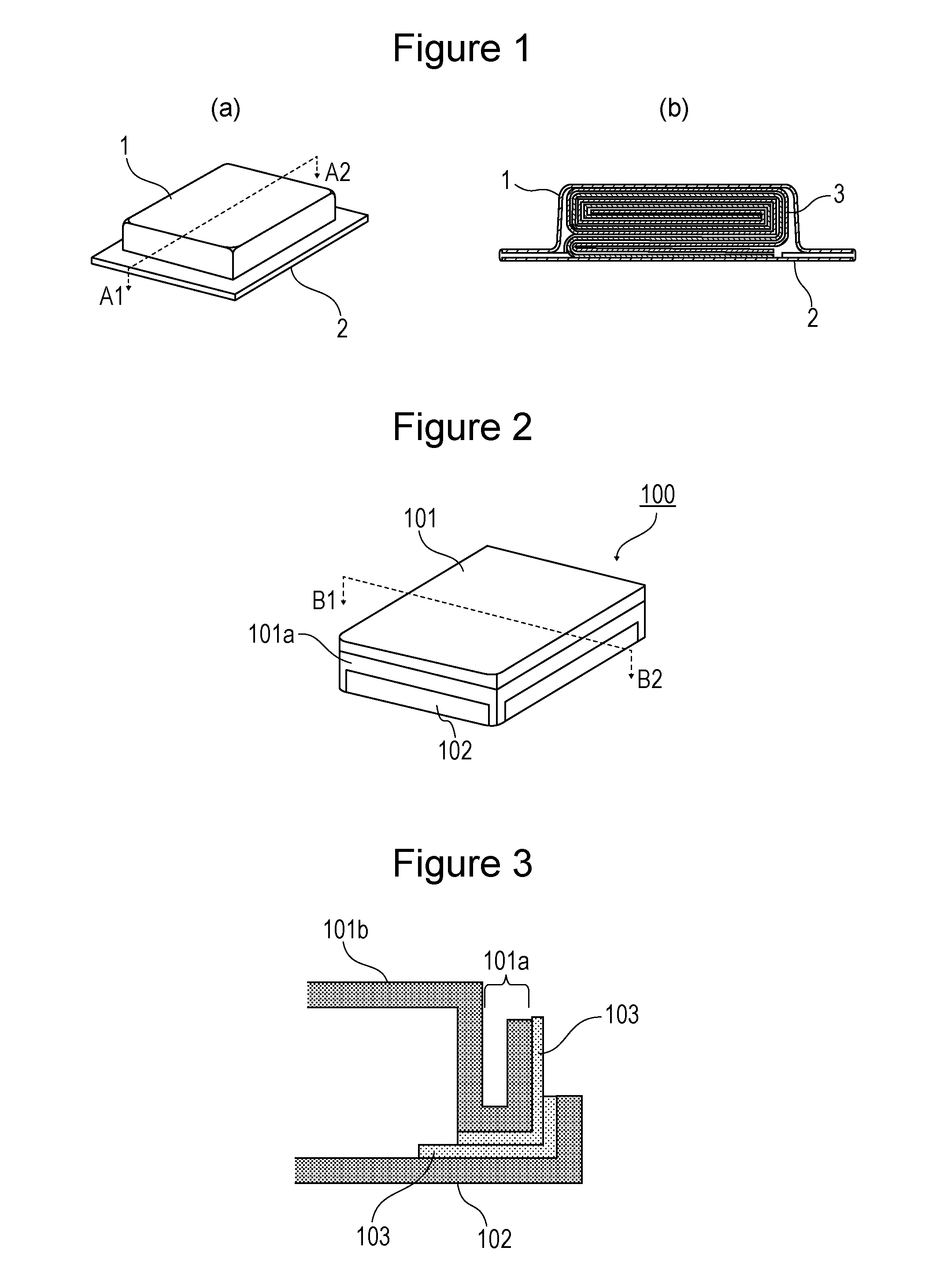
The present invention relates to a sealed storage battery that includes two metal sheets also serving as electrodes. Patent Literature 1 discloses a sealed storage battery that includes a housing composed of two metal sheets also serving as electrodes, as illustrated in a perspective view of PTL 1: Japanese Published Unexamined Patent Application No. 2004-6124 The technique described in Patent Literature 1 obviates the need for a metal terminal protruding from the housing and improves the production efficiency of the battery. However, the flange portion joining the two metal sheets decreases the total energy density of the battery. It is an object of the present invention to provide a sealed storage battery that is easy to produce, has a low short circuit risk, and has an improved total energy density. In order to achieve the object, a sealed storage battery according to the present invention is a battery that includes a first metal sheet having a recessed portion, the recessed portion having a flange portion at its periphery, a multilayer electrode assembly housed in the recessed portion, and a second metal sheet covering the flange portion and the recessed portion. The first metal sheet and the second metal sheet also serve as electrodes. The flange portion is joined to the second metal sheet with a hot-melt resin. A joint between the flange portion and the second metal sheet is folded back toward the recessed portion. An outer edge of the flange portion folded back toward the recessed portion protrudes relative to an outer edge of the second metal sheet folded back toward the recessed portion. A sealed storage battery according to the present invention has an improved total energy density because the joint between the flange portion of the first metal sheet and the second metal sheet is folded back toward the recessed portion. Furthermore, since the outer edge of the flange portion folded back toward the recessed portion protrudes relative to the outer edge of the second metal sheet folded back toward the recessed portion, a battery having a low short circuit risk can be easily produced. Embodiments of the present invention will be described in detail below. The drawings referred in the embodiments are schematically illustrated, and the dimensions of constituents in the drawings may be different from the actual dimensions of the constituents. Specific dimensions should be determined in consideration of the following description. As illustrated in A method for producing the battery 100 will be described below. <Production of Positive Electrode> 94 parts by weight of a positive-electrode active material LiCoO2, 3 parts by weight of a conductive aid carbon black, and 3 parts by weight of a poly(vinylidene fluoride) binder were mixed with a N-methyl-2-pyrrolidone (NMP) solution serving as a solvent to prepare a positive electrode slurry. The positive electrode slurry was applied to both faces of a positive electrode current collector formed of aluminum foil having a thickness of 15 μm and was dried to form a positive electrode active material layer. The positive electrode active material layer was then pressed with a roller and was cut into a belt-like positive electrode of a predetermined size. The completed positive electrode was placed on a negative electrode with a separator interposed therebetween and was wound to form an electrode assembly having a winding structure. The outermost periphery of the electrode assembly was not coated with a positive electrode mixture paste, thereby leaving an exposed portion on both faces of the positive electrode current collector. The positive electrode had a width of 332 mm and a height of 22 mm. The exposed portion at the outermost periphery of the wound positive electrode current collector had a length of 20 mm. <Production of Negative Electrode> 96% by mass of a graphite powder serving as a negative-electrode active material, 2% by mass of a carboxymethylcellulose (CMC) binder, 2% by mass of styrene-butadiene rubber (SBR), and pure water serving as a solvent were mixed to prepare a negative electrode slurry. The negative electrode slurry was applied to both faces of a negative electrode current collector formed of copper foil having a thickness of 10 μm and was dried to form a negative electrode slurry. The negative electrode slurry was then pressed with a roller and was cut into a sheet-like negative electrode of a predetermined size. The completed negative electrode was placed on a positive electrode with a separator interposed therebetween and was wound to form an electrode assembly having a winding structure. The outermost periphery of the electrode assembly was not coated with a paste containing a negative electrode, thereby leaving an exposed portion on both faces of the negative electrode current collector. The negative electrode had a width of 331 mm and a height of 23 mm. The exposed portion at the outermost periphery of the wound negative electrode current collector had a length of 20 mm. <Preparation of Non-Aqueous Electrolytic Solution> 1 M (mol/l) of LiPF6was dissolved in a mixed solvent of ethylene carbonate (EC) and diethyl carbonate (DEC) mixed at a volume ratio of 30:70 to prepare a non-aqueous electrolytic solution. <Production of Multilayer Electrode Assembly> The positive electrode and the negative electrode were wound with a polyethylene microporous membrane (width: 751 mm, height: 24 mm, thickness: 20 μm) separator interposed therebetween and were pressed flat. The separator was then fixed with a tape. <Production of Battery> A first metal sheet 101 illustrated in The recessed portion 101 A 70 μm hot-melt resin 103 was deposited in advance on the flange portion 101 The exposed portion of the positive electrode current collector was welded to the inner surface of the recessed portion 101 The flange portion 101 The flange portion 101 In the battery 100 according to the first embodiment having no metal terminal for collecting electric current, the flange portion 101 The recessed portion for folding back is formed, for example, by press working or notching of the first metal sheets 101 and 102. When a recessed portion for folding back is formed by press working in the first metal sheet 101 or 102, a raised portion may be formed opposite the recessed portion of each metal sheet. The phrase “a joint between a flange portion 101 Each outer edge of the flange portion 101 The flange portion 101 Except for the recessed portion 101 The hot-melt resin 103 may be a modified polyolefin. The hot-melt resin may have a heat-resistant layer. The heat-resistant layer may be formed of polyimide. Although the flange portion 101 In the case where the second metal sheet 102 is a flat sheet, the hot-melt resin 103 on the second metal sheet 102 can extend 0.1 to 3 mm from the bonded inner edge and thereby more reliably prevent the short circuit between the positive and negative metal sheets. Although the second metal sheet 102 is a flat sheet in the first embodiment, the second metal sheet 102 may have a recessed portion and a flange portion, like the first metal sheet 101. The first metal sheets 101 and 102 may be formed of aluminum, stainless steel, nickel, and/or copper. The first metal sheets 101 and 102 preferably have a thickness in the range of 10 to 300 μm. [Others] The positive-electrode active material is not limited to lithium cobalt oxide used in the first embodiment and may be lithium nickel oxide, lithium manganese oxide, lithium cobalt nickel composite oxide, lithium cobalt manganese composite oxide, lithium nickel manganese composite oxide, or one of these compounds in which these transition metal elements are partly substituted with Al, Mg, Zr, and/or the like. The negative-electrode active material may be any material that allows intercalation/deintercalation of lithium ions, such as graphite, coke, tin oxide, metallic lithium, silicon, or a mixture thereof, as well as graphite such as natural graphite or artificial graphite. The non-aqueous electrolytic solution is also not limited to one described in the first embodiment. For example, LiBF4, LiPF6, LiN(SO2CF3)2, LiN(SO2C2F5)2, and/or LiPF6−x(CnF2n+1)x[1<x<6, n=1 or 2] may be used alone or in combination as a supporting salt or supporting salts. The concentration of the supporting salt is not particularly limited and desirably ranges from 0.8 to 1.8 mol per liter of electrolytic solution. Apart from EC and MEC, the type of solvent is preferably a carbonate solvent, such as propylene carbonate (PC), γ-butyrolactone (GBL), ethyl methyl carbonate (EMC), dimethyl carbonate (DMC), or diethyl carbonate (DEC), more preferably a combination of a cyclic carbonate and a chain carbonate. A polymer electrolyte as well as a non-aqueous electrolytic solution may be used as a non-aqueous electrolyte. 1 Housing and positive electrode, 2 housing and negative electrode, 3 electric-power generating element, 100 battery, 101 first metal sheet, 101 A sealed storage battery that is easy to produce, has a low short circuit risk, and has an improved total energy density is provided. A battery includes a first metal sheet having a recessed portion, the recessed portion having a flange portion at its periphery, a multilayer electrode assembly housed in the recessed portion, and a second metal sheet covering the flange portion and the recessed portion. The first metal sheet and the second metal sheet also serve as electrodes. The flange portion is joined to the second metal sheet with a hot-melt resin. A joint between the flange portion and the second metal sheet is folded back toward the recessed portion. An outer edge of the flange portion folded back toward the recessed portion protrudes relative to an outer edge of the second metal sheet folded back toward the recessed portion. 1. A sealed storage battery comprising: a first metal sheet having a recessed portion, the recessed portion having a flange portion at its periphery; a multilayer electrode assembly in the recessed portion; and a second metal sheet covering the flange portion and the recessed portion,
wherein the first metal sheet and the second metal sheet also serve as electrodes, the flange portion is joined to the second metal sheet with a hot-melt resin, a joint between the flange portion and the second metal sheet is folded back toward the recessed portion, and an outer edge of the flange portion folded back toward the recessed portion protrudes relative to an outer edge of the second metal sheet folded back toward the recessed portion. 2. The sealed storage battery according to 3. The sealed storage battery according to TECHNICAL FIELD
BACKGROUND ART
CITATION LIST
Patent Literature
SUMMARY OF INVENTION
Technical Problem
Solution to Problem
Advantageous Effects of Invention
BRIEF DESCRIPTION OF DRAWINGS
DESCRIPTION OF EMBODIMENTS
First Embodiment
Modified Examples
REFERENCE SIGNS LIST