SURGICAL END EFFECTORS AND PULLEY ASSEMBLIES THEREOF
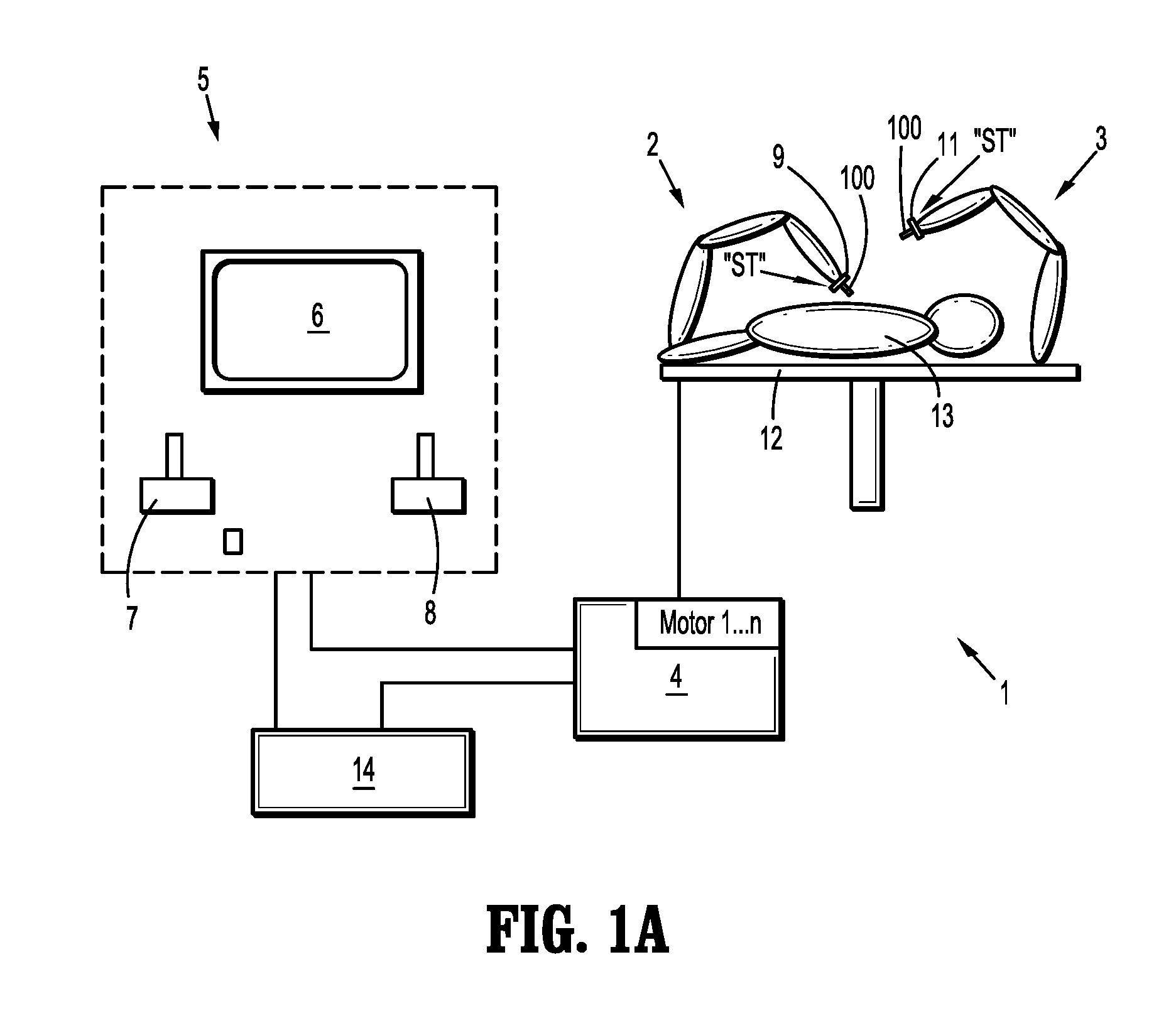
This application is a U.S. National Stage Application filed under 35 U.S.C. §371(a) of International Patent Application Serial No. PCT/US2014/064006, filed Nov. 5, 2014, which claims the benefit of each of U.S. Provisional Patent Application Ser. No. 61/938,732, filed Feb. 12, 2014, and U.S. Provisional Patent Application Ser. No. 61/938,728, filed Feb. 12, 2014, the entire disclosure of each of which are incorporated by reference herein. Robotic surgical systems have been used in minimally invasive medical procedures. Some robotic surgical systems included a console supporting a robot arm, and at least one end effector such as forceps or a grasping tool including jaws for capturing tissue therebetween. The at least one end effector was mounted to the robot arm. During a medical procedure, the end effector was inserted into a small incision (via a cannula) or a natural orifice of a patient to position the end effector at a work site within the body of the patient. Cables extended from the console, through the robot arm, and connected to the end effector. In some instances, the cables were actuated by means of motors that were controlled by a processing system including a user interface for a surgeon or clinician to be able to control the robotic surgical system including the robot arm and/or the end effector. The cables connected to a pulley assembly that transferred torque to drive the actuation of the end effector. In some instances, surgical procedures may require fine control of the end effector to grasp tissue for dissection and/or to spread tissue surfaces for deep tissue access. Accordingly, there is a need for surgical tools that are able to provide precisely controlled forces applied by jaws of an end effector of a robotic surgical system. Jaws at the end of surgical robotics tools, such as forceps or scissor cutting tools, may be driven by a pulley assembly including pulleys and cables. Methods for actuating an end effector at the end of the jaws are provided in some embodiments. Some methods may include rotating a driving pulley in an end effector of a surgical tool in a first direction about a first axis to open a first jaw and a second jaw, each being pivotable about a second axis. The end effector may include a first driven pulley attached to the first jaw and a second driven pulley attached to the second jaw. The first and second driven pulleys may be rotatable about the second axis. Each driven pulley may include a first radial side and a second radial side. A first cable may have a first end portion, a second end portion, and an intermediate portion. The first end portion may be connected to the first radial side of the first driven pulley. The second end portion may be connected to the second radial side of the second driven pulley. The intermediate portion may be connected to the driving pulley. The second cable may have a first end portion, a second end portion, and an intermediate portion. The first end portion may be connected to the first radial side of the second driven pulley. The second end portion may be connected to the second radial side of the first driven pulley. The intermediate portion may be connected to the driving pulley. Rotating the driving pulley in a second direction about the first axis may close the first and second jaws about the second axis. The first and the second driven pulleys may be rotated via the first cable responsive to rotating the driving pulley in the first direction. The first and the second driven pulleys may be rotated via the second cable responsive to rotating the driving pulley in the second direction. The first cable may be tensioned and the second cable may be slackened during rotation of the driving pulley in the first direction. The second cable may be tensioned and the first cable may be slackened during rotation of the driving pulley in the second direction. The intermediate portions of the first and second cables may be connected to a common point of the driving pulley. In some instances, the intermediate portions of the first and second cables may be crimped to the driving pulley. The first end portion of the first cable may be parallel to the second end portion of the second cable. The first end portion of the second cable may be crossed with the second end portion of the first cable. In some instances, a proximal end of the first jaw may be fixedly attached to a circumferential edge of the first drive pulley and a proximal end of the second jaw may be fixedly attached to a circumferential edge of the second drive pulley. A toothed portion may be created in the first and the second jaws. The first axis may be spaced a lateral distance from the second axis. The first and second cables may be connected to the driving pulley at a location offset a radial distance from the second axis. The intermediate portions of the first and second cables may be looped through an anchor member on the driving pulley. A hook may be attached to a circumferential edge of the driving pulley. In some instances, a method may include coupling a plurality of cable sections to a plurality of jaw pulleys with at least one cable section coupled to each of at least two radial sides of each jaw pulley. Each jaw pulley may be connected to a corresponding jaw. Each of the cable sections may be also be coupled to a driving pulley. The driving pulley may be rotated in a first and a second direction to rotate each of the jaw pulleys and at least one of open and close the jaws. Rotating the driving pulley in the first direction may create a tension in a different cable section coupled to each jaw pulley than rotating the driving pulley in the second direction. Each of the cable sections may be separate cables or at least two of the cable sections may be part of a single continuous cable. A first segment of a first cable section of a continuous cable including at least two of the plurality of cable sections may be coupled to a radial side of a first jaw pulley. A second segment of the first cable section may be coupled to the driving pulley. A first segment of a second cable section of the continuous cable may be coupled to the driving pulley. A second segment of the second cable section may be coupled to a different radial side of the second jaw pulley. A single segment of the continuous cable may be coupled to the driving pulley when the second segment of the first cable section coincides with the first segment of the second cable section. At least two segments of the continuous cable may be coupled to the driving pulley when the second segment of the first cable section does not coincide with the first segment of the second cable section. In some instances a first segment of a first cable section of a continuous cable including at least two of the plurality of cable sections may be coupled to a radial side of a first jaw pulley. A second segment of the first cable section may be coupled to the driving pulley. A first segment of a second cable section of the continuous cable may be coupled to the driving pulley. A second segment of the second cable section may be coupled to a different radial side of the first jaw pulley. A single segment of the continuous cable may be coupled to the driving pulley when the second segment of the first cable section coincides with the first segment of the second cable section. Further details and aspects of exemplary embodiments of the present disclosure are described in more detail below with reference to the appended figures. As used herein, the terms parallel and perpendicular are understood to include relative configurations that are substantially parallel and substantially perpendicular, such as up to about + or −10 degrees from true parallel and true perpendicular. Embodiments of the present disclosure are described herein with reference to the accompanying drawings, wherein: Embodiments of the presently disclosed surgical end effectors and methods of actuating the same are described in detail with reference to the drawings, in which like reference numerals designate identical or corresponding elements in each of the several views. As used herein the term “distal” refers to that portion of the jaws and/or pulley assembly that is closer to a surgical site, while the term “proximal” refers to that portion of the jaws and/or pulley assembly that is farther from the surgical site. Referring initially to Each of the robot arms 2, 3 includes an attaching device 9, 11, to which may be attached, for example, a surgical tool “ST” supporting an end effector 100, in accordance with any one of several embodiments disclosed herein, as will be described in greater detail below. Robot arms 2, 3 may be driven by electric drives (not shown) that are connected to control device 4. Control device 4 (e.g., a computer) is set up to activate the drives, in particular by means of a computer program, in such a way that robot arms 2, 3, their attaching devices 9, 11 and thus the surgical tool (including end effector 100) execute a desired movement according to a movement defined by means of manual input devices 7, 8. Control device 4 may also be set up in such a way that it regulates the movement of robot arms 2, 3 and/or of the drives. Medical work station 1 is configured for use on a patient 13 lying on a patient table 12 to be treated in a minimally invasive manner by means of end effector 100. Medical work station 1 may also include one or more robot arms 2, 3, the additional robot arms likewise being connected to control device 4 and being telemanipulatable by means of operating console 5. A medical instrument or surgical tool (including an end effector 100) may also be attached to the additional robot arm. Medical work station 1 may include a database 14, in particular coupled to with control device 4, in which are stored for example pre-operative data from patient 13 and/or anatomical atlases. Reference may be made to U.S. Patent Publication No. 2012/0116416, filed on Nov. 3, 2011, entitled “Medical Workstation,” the entire content of which is incorporated herein by reference, for a detailed discussion of the construction and operation of medical work station 1. Control device 4 may control a plurality of motors (Motor 1 . . . n) with each motor configured to wind-up or let out a length of cable “C” ( Turning now to End effector 100 includes a pulley assembly 120 disposed therein for actuating jaws 102 In another embodiment that is a variation of that shown in This configuration may result in a tensioning of a first section of cables C1 and C2 during a rotation of the driving pulley 140 in a first direction as well as a slacking of the other second section of cables C1 and C2. A tensioning of the second sections of cables C1 and C2 and a slacking of the first sections of cables C1 and C2 may occur when rotating the driving pulley 140 in the opposite direction. Other cable routings may be possible in different embodiments. In embodiments, jaws 102 Each driven pulley 122 Driven pulleys 122 First driven pulley 122 Pulley assembly 120 further includes a driving pulley 140, similar to first and second driven pulleys 122 Driving pulley 140 has a circular configuration and defines a circumferential edge 142. Circumferential edge 142 defines an arcuate channel or groove 144 extending along a circumference of driving pulley 140. Channel or groove 144 is configured for disposal of each of cables “C1,” “C2.” Driving pulley 140 includes a first radial side 146 and a second radial side 148 each defining a semicircular portion of driving pulley 140, as demarcated by dotted line “L3” in Driving pulley 140 supports an anchor member 150 attached to a proximal-most portion of circumferential edge 142. Anchor member 150 secures both cables “C1,” “C2” to drive pulley 140 such that, as driving pulley 140 is rotated, cables “C1,” “C2” move therewith. In embodiments, anchor member 150 may be a hook onto which cables “C1,” “C2” are attached. In other embodiments, anchor member 150 may be a crimp that secures cables “C1,” “C2” to circumferential edge 142 of driving pulley 140. In use, a rotation of driving pulley 140 about second axis “X2” via motor (Motor 1 . . . n) and cable “C” causes first and second driven pulleys 122 Pulley assembly 120 may further includes a first cable “C1” and a second cable “C2.” First cable “C1” and second cable “C2” each have a first end portion 160 First cable “C1” is secured by anchor member 150 of driving pulley 140 to a proximal-most portion of circumferential edge 142 of driving pulley 140 such that intermediate portion or looped portion 164 First end portion 160 First end portion 160 Second cable “C2” is secured by anchor member 150 of driving pulley 140 to a proximal-most portion of circumferential edge 142 of driving pulley 140 such that intermediate portion or looped portion 164 First end portion 160 First end portion 160 In one embodiment, first cable “C1” includes two cables each having a first end connected to driving pulley 140 at a common point and a second end connected to first radial side 130 In operation, motor (Motor 1 . . . n) is energized to rotate and, in turn, drive a letting out or winding-up or a rotation of cable “C.” As cable “C” is actuated, cable “C” drives the rotation of driving pulley 140 in one of a clockwise and counter-clockwise direction. A rotation of driving pulley 140 in a first direction, indicated by arrow “A1” shown in A rotation of driving pulley 140 in a second direction, indicated by arrow “B1” shown in In one embodiment, as shown in Pulley assembly 220 includes a first driven pulley 222 First driven pulley 222 Driving pulley 240 is spaced a lateral distance from first and second driven pulleys 222 First cable “C3” is looped or wrapped about circumferential edge 242 of driving pulley 240 and circumferential edge 226 In use, a rotation of driving pulley 240 via motor (Motor 1 . . . n) and cable “C” causes first and second driven pulleys 222 It will be understood that various modifications may be made to the embodiments disclosed herein. For example, while the driven pulleys disclosed herein have been shown and described as being connected to the proximal ends of the jaws, it is contemplated and within the scope of the present disclosure, for the driven pulleys to be operatively connected with the distal portion of the jaws. Therefore, the above description should not be construed as limiting, but merely as exemplifications of various embodiments. Those skilled in the art will envision other modifications within the scope and spirit of the claims appended thereto. An end effector of a surgical tool includes a first jaw and a second jaw rotated by a driving pulley. A first driven pulley is attached to the first jaw and a second driven pulley is attached to the second jaw. A first end portion of a first cable is connected to a first radial side of the first driven pulley, a second end portion of the first cable is connected to a second radial side of the second driven pulley, and an intermediate portion of the first cable is connected to the driving pulley. A first end portion of a second cable is connected to a first radial side of the second driven pulley, a second end portion of the second cable is connected to a second radial side of the first driven pulley, and an intermediate portion of the second cable is connected to the driving pulley. 1. A method of actuating an end effector, comprising:
rotating a driving pulley in an end effector of a surgical tool in a first direction about a first axis to open a first jaw and a second jaw each being pivotable about a second axis, the end effector including:
a first driven pulley attached to the first jaw and a second driven pulley attached to the second jaw, the first and second driven pulleys being rotatable about the second axis, each driven pulley including a first radial side and a second radial side; a first cable having a first end portion, a second end portion, and an intermediate portion, the first end portion connected to the first radial side of the first driven pulley, the second end portion connected to the second radial side of the second driven pulley, and the intermediate portion connected to the driving pulley; and a second cable having a first end portion, a second end portion, and an intermediate portion, the first end portion connected to the first radial side of the second driven pulley, the second end portion connected to the second radial side of the first driven pulley, and the intermediate portion connected to the driving pulley; and rotating the driving pulley in a second direction about the first axis to close the first and second jaws about the second axis. 2. The method as recited in rotating the first and the second driven pulleys via the first cable responsive to rotating the driving pulley in the first direction; and rotating the first and the second driven pulleys via the second cable responsive to rotating the driving pulley in the second direction. 3. The method as recited in tensioning the first cable and slacking the second cable during rotation of the driving pulley in the first direction and the second cable is in a slack condition; and tensioning the second cable and slacking the first cable during rotation of the driving pulley in the second direction. 4. The method as recited in 5. The method as recited in 6. The method as recited in positioning the first end portion of the first cable parallel to the second end portion of the second cable; and crossing the first end portion of the second cable and the second end portion of the first cable. 7. The method as recited in 8. The method as recited in 9. The method as recited in 10. The method as recited in 11. The method as recited in 12. The method as recited in 13. A method comprising:
coupling a plurality of cable sections to a plurality of jaw pulleys with at least one cable section coupled to each of at least two radial sides of each jaw pulley, each jaw pulley connected to a corresponding jaw; coupling each of the cable sections to a driving pulley; changing a direction of rotation of the driving pulley from a first direction to a second direction; and responsive to changing the direction of rotation of the driving pulley, changing a direction of rotation of each of the jaw pulleys, creating a tension in a different cable section coupled to each jaw pulley, and alternating between opening and closing the jaws. 14. The method as recited in 15. The method as recited in 16. The method as recited in coupling a first segment of a first cable section of a continuous cable including at least two of the plurality of cable sections to a radial side of a first jaw pulley; coupling a second segment of the first cable section to the driving pulley; coupling a first segment of a second cable section of the continuous cable to the driving pulley; and coupling a second segment of the second cable section to a different radial side of the second jaw pulley. 17. The method as recited in 18. The method as recited in 19. The method as recited in coupling a first segment of a first cable section of a continuous cable including at least two of the plurality of cable sections to a radial side of a first jaw pulley; coupling a second segment of the first cable section to the driving pulley; coupling a first segment of a second cable section of the continuous cable to the driving pulley; and coupling a second segment of the second cable section to a different radial side of the first jaw pulley. 20. The method as recited in CROSS-REFERENCE TO RELATED APPLICATIONS
BACKGROUND
SUMMARY
BRIEF DESCRIPTION OF THE DRAWINGS
DETAILED DESCRIPTION