ANTENNA FOR DOWNHOLE COMMUNICATION USING SURFACE WAVES
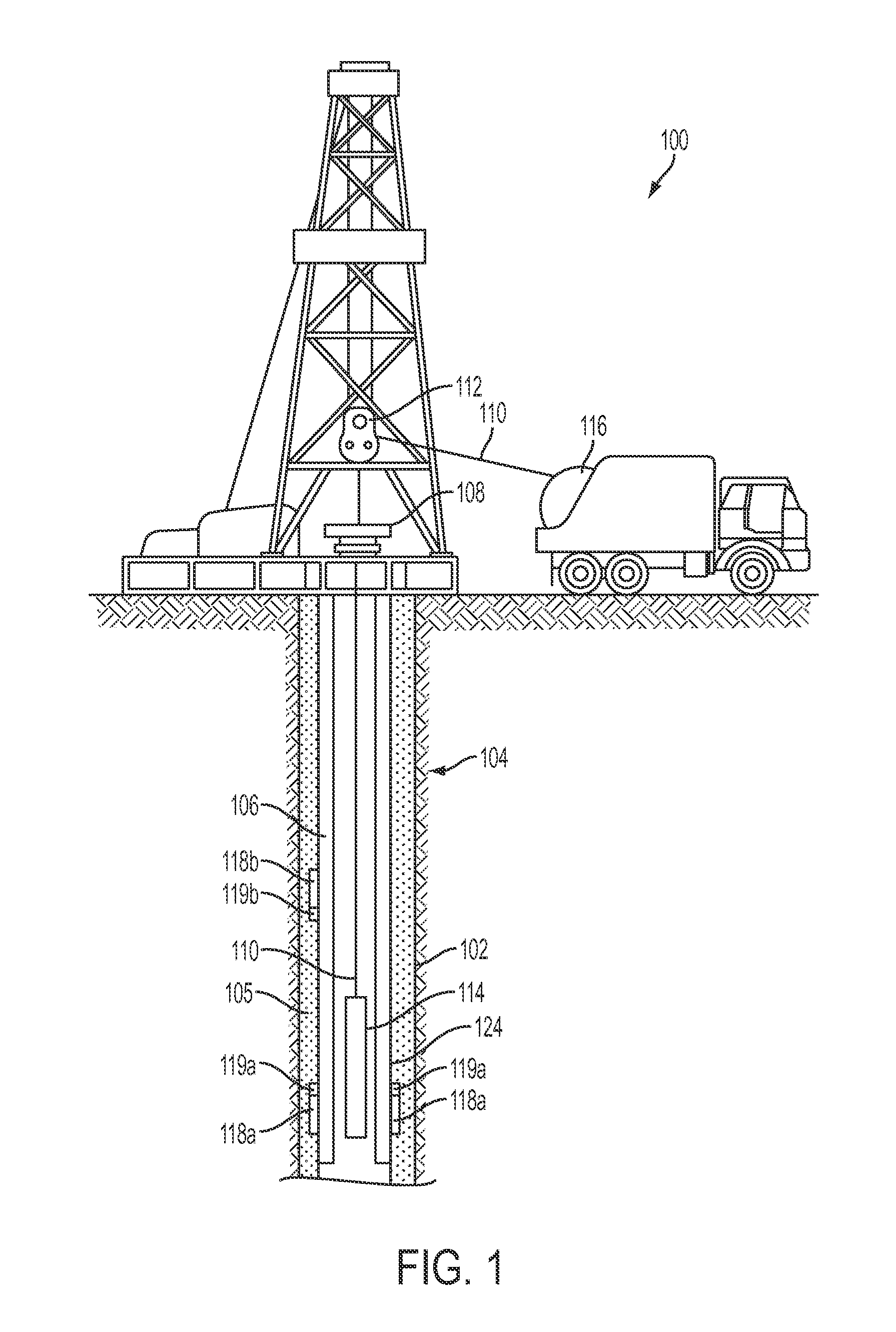
The present disclosure relates generally to devices for use in well systems. More specifically, but not by way of limitation, this disclosure relates to an antenna for downhole communication using surface waves. A well system (e.g., an oil or gas well for extracting fluid or gas from a subterranean formation) can include various sensors. For example, a well system can include sensors for measuring well system parameters, such as temperature, pressure, resistivity, or sound levels. In some examples, the sensors can transmit data via cables to a well operator (e.g., typically at the surface of the well system). Cables can wear or fail, however, due to the harsh downhole environment or impacts with well tools. It can be challenging to communicate data from the sensors to the well surface efficiently. Certain aspects and features of the present disclosure are directed to an antenna for downhole communication using surface waves. The antenna can include a cylindrically shaped (e.g., donut shaped) conductor with an inner diameter that is positioned coaxially around an outer surface of a casing string in a wellbore. For example, the antenna can include a toroid antenna or a solenoid antenna that is positioned coaxially around the outer surface of the casing string. Upon applying power to the cylindrically shaped conductor, the antenna can generate a magnetic field component of a surface wave (described in greater detail below) that can be used for wirelessly communicating data. In some examples, the antenna can include a pair of conductive plates. In some examples, the conductive plates can be positioned in parallel to one another with a gap between the conductive plates. Upon applying power across the pair of conductive plates, the antenna can generate an electric field component of the surface wave. In some examples, the conductive plates can be oriented along a longitudinal axis of the casing string. The antenna can be electrically coupled to a transceiver. The transceiver can be positioned external to the casing string. The transceiver can be positioned external to the casing string if it is positioned on or external to an outer diameter or outer wall of the casing string. The transceiver can operate the antenna to generate surface waves. For example, a transceiver can transmit power to the cylindrically shaped conductor, the pair of conductive plates, or both at a frequency within a specific frequency band to transmit data. In some examples, the specific frequency band can be between 1 kHz and 700 kHz. This specific frequency band can include a range of frequencies that causes the antenna to generate surface waves. In some examples, transmitting power to the antenna at a frequency outside the specific frequency band can cause the antenna to generate inductive fields, rather than surface waves. The surface waves can propagate along the interface surface between the casing string and a cement sheath positioned in the wellbore (e.g., coupling the casing string to the walls of the wellbore). Another transceiver can detect the surface waves via an antenna to receive the data. A surface wave can include an electromagnetic wave that propagates along an interface surface between two different media (e.g., two different solids or fluids) and does not produce electromagnetic radiation. The surface wave can include an electric field, a magnetic field, or both that are non-transverse (e.g., not orthogonal) to the direction of propagation. For example, the electric field, the magnetic field, or both can be oriented in the direction of propagation (e.g., parallel to the direction of propagation) of the electromagnetic wave. As another example, the electric field, the magnetic field, or both can be at an acute angle to the direction of propagation of the electromagnetic wave. Surface waves can differ from other types of electromagnetic waves in multiple ways. For example, absorption of surface wave's energy can be strictly within the media through which the surface wave propagates. This absorption of energy can be very closely confined to a thin volume of material on either side of the interface surface. This is unlike other forms of electromagnetic waves, which may carry energy away from the media from which the electromagnetic waves originate or through which the electromagnetic waves propagate. For example, other forms of electromagnetic waves that propagate through, for example, a waveguide can leak energy through the waveguide and emit radiation into the media surrounding the waveguide. In some examples, surface waves can travel farther distances with less attenuation than other methods of downhole wireless communication. For example, an inductive field transmitted into the subterranean formation of the wellbore can propagate through the subterranean formation to a receiving wireless communication device. But the inductive field can attenuate and distort based on the characteristics (e.g., the conductivity) of the subterranean formation, which may be impractical or infeasible to control. Surface waves can propagate along the interface surface between a cement sheath and a casing string in a wellbore, rather than through the subterranean formation. Because the cement sheath and the casing string are both man-made well components, it can be easier to control the characteristics (e.g., conductivity and geometry) of the interface surface. For example, the casing string can include a material (e.g., metal) and shape configured to improve or optimize surface wave propagation. This can allow wireless communications via surface waves to have improved power transmission efficiency over larger distances. In some examples, the cylindrically shaped antenna can be positioned coaxially around the casing string via a cylindrically shaped substrate. The cylindrically shaped substrate can be positioned coaxially around the casing string. For example, the cylindrically shaped substrate can be positioned between the inner diameter of the cylindrically shaped conductor and an outer diameter of the outer surface of the casing string. The cylindrically shaped substrate can include an insulator (e.g., rubber or plastic) for electrically insulating the cylindrically shaped antenna from the casing string. In some examples, the conductive plates can be positioned on the cylindrically shaped substrate. For example, the conductive plates can be positioned on the cylindrically shaped substrate and in parallel to one another for generating the electric field component of the surface wave. In other examples, the conductive plates can be positioned on a longitudinal substrate that is coupled (e.g., perpendicularly) to the cylindrically shaped substrate. The longitudinal substrate can be oriented along the longitudinal axis of the casing string or at an angle to the longitudinal axis of the casing string. For example, the conductive plates can be positioned at a longitudinal end of the longitudinal substrate and in parallel to one another for generating the electric field component of the surface wave. In some examples, the pair of conductive plates can each be positioned on separate longitudinal substrates. The separate longitudinal substrates can each be coupled (e.g., perpendicularly) to the cylindrically shaped substrate. In some examples, the longitudinal substrates can each be oriented along the longitudinal axis of the casing string or at an angle to the longitudinal axis of the casing string. In some examples, each of the conductive plates can be oriented on a respective longitudinal substrate such that the pair of conductive plates are parallel to one another. These illustrative examples are given to introduce the reader to the general subject matter discussed here and are not intended to limit the scope of the disclosed concepts. The following sections describe various additional features and examples with reference to the drawings in which like numerals indicate like elements, and directional descriptions are used to describe the illustrative aspects but, like the illustrative aspects, should not be used to limit the present disclosure. The well system 100 can also include at least one well tool 114 (e.g., a formation-testing tool). The well tool 114 can be coupled to a wireline 110, slickline, or coiled tube that can be deployed into the wellbore 102. The wireline 110, slickline, or coiled tube can be guided into the wellbore 102 using, for example, a guide 112 or winch. In some examples, the wireline 110, slickline, or coiled tube can be wound around a reel 116. The well system 100 can include transceivers 118 The transceivers 118 In some examples, the transceivers 118 The transceivers 118 More specifically, in some examples, assuming that the casing string 210 is cylindrical, and defining “z” as a z-axis that is an axis of symmetry of the casing string 210, a radial coordinate “r” as orthogonal to the z-axis, and a polar coordinate θ, the surfaces waves 214 can propagate along the casing string 210 according to the following mathematical equations: where Hθ is the polar component of magnetic field intensity outside of the casing string 210; Ezis the electric field component along the casing string 210; Eris the radial component of the electric field (e.g., orthogonal to the casing string 210); A is the source-dependent amplitude; i=√{square root over (−1)}; ε1 is the effective dielectric constant of the casing string 210; μ0=4π(10−7) Henrys/meter, the permeability of free space; σ1is the conductivity (in mhos/m) of the material within the casing string 210; σ2is the conductivity (in mhos/m) of the material outside of the casing string 210; and ω is equal to 2 πƒ, where ƒ is the frequency in Hertz. In some examples, σ1>>σ2so that σeff˜σ2and rσ<<1. In some examples, because Ezis not vanishing, the electric field can be tilted with respect to a normal direction to the casing string 210. The surface waves 214 can propagate along the z-axis according to the following mathematical equation: where is the reciprocal of the “skin depth” in the medium outside of the casing string 210. Because of this factor, in some examples, the frequency should be kept as low as possible while sustaining the required data rate. In some examples, the transceivers 118 In some examples, the transceivers 118 The surface wave 214 can include an electric field, a magnetic field, or both that can be oriented at an acute angle to a direction of propagation of the surface wave 214 (e.g., the direction from 118 In some examples, the surface wave 214 can include a Zenneck surface wave, a Sommerfeld surface wave, a radial-cylindrical surface wave, an axial-cylindrical surface wave, or any combination of these. The type of surface wave 214 can depend on the geometry of the interface between the casing string 210 and the cement sheath 208. For example, the cylindrical geometries of the casing string 210 and the cement sheath 208 can allow the transceivers 118 The characteristics of the surface wave 214 can also depend on the configuration of the antenna 119 The transceivers 118 In some examples, a transceiver 118 In some examples, the sensor 218 can transmit sensor signals to a processor (e.g., associated with a transceiver 118 The antenna 300 can include the cylindrically shaped conductor 306. The cylindrically shaped conductor 306 can include a toroid antenna or a solenoid antenna. The cylindrically shaped conductor 306 can be positioned coaxially around (and coupled to) an outer surface 305 of the cylindrically shaped substrate 304. In some examples, the cylindrically shaped conductor 306 can be positioned perpendicularly to a longitudinal axis 310 of the casing string 302. In other examples (e.g., the example shown in In some examples, the antenna 300 can include a longitudinal substrate 308. In some examples, the longitudinal substrate 308 can be positioned perpendicularly to the cylindrically shaped conductor 306 and along the longitudinal axis 310 of the casing string 302. In other examples (e.g., the example shown in The longitudinal substrate 308 can include a pair of conductive plates 312 In some examples, the antenna 300 can include both the cylindrically shaped conductor 306 and the pair of conductive plates 312 The antenna 400 can also include a pair of longitudinal substrates 408 Each longitudinal substrate 408 Alternative configurations of the conductive plates 312 In some examples, the antenna 800 can also include a pair of longitudinal substrates 408 Conductive plates 312 The transceiver 118 can include a computing device 602. The computing device 602 can include a processor 604, a memory 608, and a bus 606. The processor 604 can execute one or more operations for operating a transceiver. The processor 604 can execute instructions 610 stored in the memory 608 to perform the operations. The processor 604 can include one processing device or multiple processing devices. Non-limiting examples of the processor 604 include a Field-Programmable Gate Array (“FPGA”), an application-specific integrated circuit (“ASIC”), a microprocessor, etc. The processor 604 can be communicatively coupled to the memory 608 via the bus 606. The non-volatile memory 608 may include any type of memory device that retains stored information when powered off. Non-limiting examples of the memory 608 include electrically erasable and programmable read-only memory (“EEPROM”), flash memory, or any other type of non-volatile memory. In some examples, at least some of the memory 608 can include a medium from which the processor 604 can read the instructions 610. A computer-readable medium can include electronic, optical, magnetic, or other storage devices capable of providing the processor 604 with computer-readable instructions or other program code. Non-limiting examples of a computer-readable medium include (but are not limited to) magnetic disk(s), memory chip(s), ROM, random-access memory (“RAM”), an ASIC, a configured processor, optical storage, or any other medium from which a computer processor can read instructions. The instructions 610 can include processor-specific instructions generated by a compiler or an interpreter from code written in any suitable computer-programming language, including, for example, C, C++, C#, etc. The transceiver 118 can include a power source 612. The power source 612 can be in electrical communication with the computing device 602, the communications interface 616, and the antenna 119. In some examples, the power source 612 can include a battery (e.g. for powering the transceiver 118). In other examples, the transceiver 118 can be coupled to and powered by an electrical cable (e.g., a wireline). Additionally or alternatively, the power source 612 can include an AC signal generator. The computing device 602 can operate the power source 612 to apply a transmission signal to the antenna 119. For example, the computing device 602 can cause the power source 612 to apply a voltage with a frequency within an onset frequency range to the antenna 119. This can cause the antenna 119 to generate a surface wave, which can be transmitted to another transceiver 118. In other examples, the computing device 602, rather than the power source 612, can apply the transmission signal to the antenna 119. The transceiver 118 can include a communications interface 616. The communications interface 616 can include or can be coupled to the antenna 119. In some examples, part or all of the communications interface 616 can be implemented in software. For example, the communications interface 616 can include instructions 610 stored in memory 608. The communications interface 616 can receive data via the antenna 119. For example, the communications interface 616 can detect surface waves via the antenna 119. In some examples, the communications interface 616 can amplify, filter, demodulate, frequency shift, and otherwise manipulate the detected surface waves. The communications interface 616 can transmit a signal associated with the detected surface waves to the processor 604. In some examples, the processor 604 can receive and analyze the signal to retrieve data associated with the detected surface waves. In some examples, the processor 604 can analyze the data and perform one or more functions. For example, the processor 604 can generate a response based on the data. The processor 604 can cause a response signal associated with the response to be transmitted to the communications interface 616. The communications interface 616 can generate surface waves via the antenna 119 to communicate the response to another transceiver 118 or communications device. In this manner, the processor 604 can receive, analyze, and respond to communications from another transceiver 118. The communications interface 616 can transmit data via the antenna 119. For example, the communications interface 616 can transmit surface waves that are modulated by data via the antenna 119. In some examples, the communications interface 616 can receive signals (e.g., associated with data to be transmitted) from the processor 604 and amplify, filter, modulate, frequency shift, and otherwise manipulate the signals. The communications interface 616 can transmit the manipulated signals to the antenna 119. The antenna 119 can receive the manipulated signals and responsively generate surface waves that carry the data. The antenna 119 can include a pair of conductive plates 312 and a cylindrically shaped conductor 306. The power source 612 or the computing device 602 can apply power (e.g., via the communications interface 616) at a frequency within an onset frequency range to the pair of conductive plates 312, the cylindrically shaped conductor 306, or both. This can cause the antenna 119 to generate a surface wave with a magnetic field component, an electric field component, or both. The well tool 700 can be positioned in the wellbore. In some examples, the well tool 700 is a logging-while-drilling tool. The well tool 700 can include various subsystems 702, 704, 706, 707. For example, the well tool 700 can include a subsystem 702 that includes a communication subsystem. The well tool 700 can also include a subsystem 704 that includes a saver subsystem or a rotary steerable system. A tubular section or an intermediate subsystem 706 (e.g., a mud motor or measuring-while-drilling module) can be positioned between the other subsystems 702, 704. In some examples, the well tool 700 can include a drill bit 710 for drilling the wellbore. The drill bit 710 can be coupled to another tubular section or intermediate subsystem 707 (e.g., a measuring-while-drilling module or a rotary steerable system). The well tool 700 can also include tubular joints 708 In some examples, transceivers 118 In some aspects, an antenna for downhole communication using surface waves is provided according to one or more of the following examples: An assembly can include a casing string with an outer surface. The assembly can also include an antenna for wirelessly communicating data by generating a surface wave that propagates along an interface surface. The antenna can be positioned coaxially around the casing string. The antenna can include a cylindrically shaped conductor that is positionable coaxially around the outer surface of the casing string for generating a magnetic field component of the surface wave that is non-transverse to a direction of propagation of the surface wave along the interface surface. The antenna can also include a pair of conductive plates positioned at an angle to the cylindrically shaped conductor for generating an electric field component of the surface wave. The assembly of Example #1 may feature the antenna being operable to generate the electric field component such that the electric field component is non-transverse to the direction of propagation of the surface wave along the interface surface. The assembly of any of Examples #1-2 may feature the interface surface being between the casing string and a cement sheath. The assembly of any of Examples #1-3 may feature the angle being 0 degrees or 90 degrees. The assembly of any of Examples #1-4 may feature the antenna being operable to generate the surface wave responsive to receiving a signal with a frequency between 1 kHz and 1 MHz at the pair of conductive plates and the cylindrically shaped conductor. The assembly of any of Examples #1-5 may feature a pair of longitudinal substrates that are positioned in parallel to one another and perpendicular to the cylindrically shaped conductor so that the pair of longitudinal substrates extend along a longitudinal axis of the casing string. Each conductive plate in the pair of conductive plates can be positioned on a different longitudinal substrate in the pair of longitudinal substrates. The assembly of any of Examples #1-6 may feature a cylindrically shaped substrate that is positioned coaxially around the outer surface of the casing string. The cylindrically shaped conductor can be positioned on the cylindrically shaped substrate and a pair of longitudinal substrates can be coupled to the cylindrically shaped substrate. The assembly of any of Examples #1-7 may feature a longitudinal substrate positioned perpendicularly to the cylindrically shaped conductor and extending along a longitudinal axis of the casing string. The pair of conductive plates can be positioned at a longitudinal end of the longitudinal substrate and in parallel to one another. A system can include a transceiver positioned externally to a casing string. The system can also include an antenna communicatively coupled to the transceiver for wirelessly transmitting data using surface waves. The antenna can include a cylindrically shaped conductor that is positionable coaxially around an outer surface of the casing string for generating magnetic field components of the surface waves that are non-transverse to a direction of propagation of the surface waves along an interface surface. The antenna can also include a pair of conductive plates positioned at an angle to the cylindrically shaped conductor for generating electric field components of the surface waves. The system of Example #9 may feature the antenna being operable to generate the electric field components such that the electric field components are non-transverse to the direction of propagation of the surface waves along the interface surface. The system of any of Examples #9-10 may feature the interface surface being between the casing string and a cement sheath. The system of any of Examples #9-11 may feature the angle being 0 degrees or 90 degrees. The system of any of Examples #9-12 may feature a pair of longitudinal substrates that are positioned in parallel to one another and perpendicular to the cylindrically shaped conductor to that that the pair of longitudinal substrates extend along a longitudinal axis of the casing string. Each conductive plate in the pair of conductive plates can be positioned on a different longitudinal substrate in the pair of longitudinal substrates. The system of any of Examples #9-13 may feature a cylindrically shaped substrate that is positioned coaxially around the outer surface of the casing string. The cylindrically shaped conductor can be positioned on the cylindrically shaped substrate and a pair of longitudinal substrates can be coupled to the cylindrically shaped substrate. The system of any of Examples #9-14 may feature may feature a longitudinal substrate positioned perpendicularly to the cylindrically shaped conductor and extending along a longitudinal axis of the casing string. The pair of conductive plates can be positioned at a longitudinal end of the longitudinal substrate and in parallel to one another. An antenna that is positionable in a wellbore can include a cylindrically shaped substrate that is positioned coaxially around an outer surface of a casing string. The antenna can also include a cylindrically shaped conductor that is positioned coaxially around and coupled to the cylindrically shaped substrate for generating a magnetic field component of a surface wave. The antenna can also include a longitudinal substrate that is coupled to and positioned at an angle to the cylindrically shaped substrate. The antenna can further include a pair of conductive plates coupled to the longitudinal substrate and oriented for generating an electric field component of the surface wave. The magnetic field component and the electric field component can be non-transverse to a direction of propagation of the surface wave along an interface surface. The antenna of Example #16 may feature the interface surface being between the casing string and a cement sheath. The antenna of any of Examples #16-17 may feature the angle being 0 degrees or 90 degrees. The antenna of any of Examples #16-18 may feature the pair of conductive plates being positioned at a longitudinal end of the longitudinal substrate and in parallel to one another. The antenna of any of Examples #16-19 may feature the longitudinal substrate including a first longitudinal substrate and a second longitudinal substrate that are positioned in parallel to one another. A first conductive plate in the pair of conductive plates can be positioned on the first longitudinal substrate and a second conductive plate in the pair of conductive plates can be positioned on the second longitudinal substrate. The foregoing description of certain examples, including illustrated examples, has been presented only for the purpose of illustration and description and is not intended to be exhaustive or to limit the disclosure to the precise forms disclosed. Numerous modifications, adaptations, and uses thereof will be apparent to those skilled in the art without departing from the scope of the disclosure. An assembly can include a casing string with an outer surface. The assembly can also include an antenna for wirelessly communicating data by generating a surface wave that propagates along an interface surface. The antenna can be positioned coaxially around the casing string. The antenna can include a cylindrically shaped conductor that is positionable coaxially around an outer surface of a casing string for generating a magnetic field component of the surface wave that is non-transverse to a direction of propagation of the surface wave along the interface surface. The antenna can also include a pair of conductive plates positioned at an angle to the cylindrically shaped conductor for generating an electric field component of the surface wave. 1. An assembly comprising:
a casing string with an outer surface; and an antenna for wirelessly communicating data by generating a surface wave that propagates along an interface surface, the antenna positioned coaxially around the casing string and comprising:
a cylindrically shaped conductor that is positionable coaxially around the outer surface of the casing string for generating a magnetic field component of the surface wave that is non-transverse to a direction of propagation of the surface wave along the interface surface; and a pair of conductive plates positioned at an angle to the cylindrically shaped conductor for generating an electric field component of the surface wave. 2. The assembly of 3. The assembly of 4. The assembly of 5. The assembly of 6. The assembly of 7. The assembly of 8. The assembly of 9. A system comprising:
a transceiver positioned externally to a casing string; and an antenna communicatively coupled to the transceiver for wirelessly transmitting data using surface waves, the antenna comprising:
a cylindrically shaped conductor that is positionable coaxially around an outer surface of the casing string for generating magnetic field components of the surface waves that are non-transverse to a direction of propagation of the surface waves along an interface surface; and a pair of conductive plates positioned at an angle to the cylindrically shaped conductor for generating electric field components of the surface waves. 10. The system of 11. The system of 12. The system of 13. The system of 14. The system of 15. The system of 16. An antenna that is positionable in a wellbore, the antenna comprising:
a cylindrically shaped substrate that is positioned coaxially around an outer surface of a casing string; a cylindrically shaped conductor that is positioned coaxially around and coupled to the cylindrically shaped substrate for generating a magnetic field component of a surface wave; a longitudinal substrate that is coupled to and positioned at an angle to the cylindrically shaped substrate; and a pair of conductive plates coupled to the longitudinal substrate and oriented for generating an electric field component of the surface wave, wherein the magnetic field component and the electric field component are non-transverse to a direction of propagation of the surface wave along an interface surface. 17. The antenna of 18. The antenna of 19. The antenna of 20. The antenna of TECHNICAL FIELD
BACKGROUND
BRIEF DESCRIPTION OF THE DRAWINGS
DETAILED DESCRIPTION
Example #1
Example #2
Example #3
Example #4
Example #5
Example #6
Example #7
Example #8
Example #9
Example #10
Example #11
Example #12
Example #13
Example #14
Example #15
Example #16
Example #17
Example #18
Example #19
Example #20