GAP ASSESSMENT TOOL
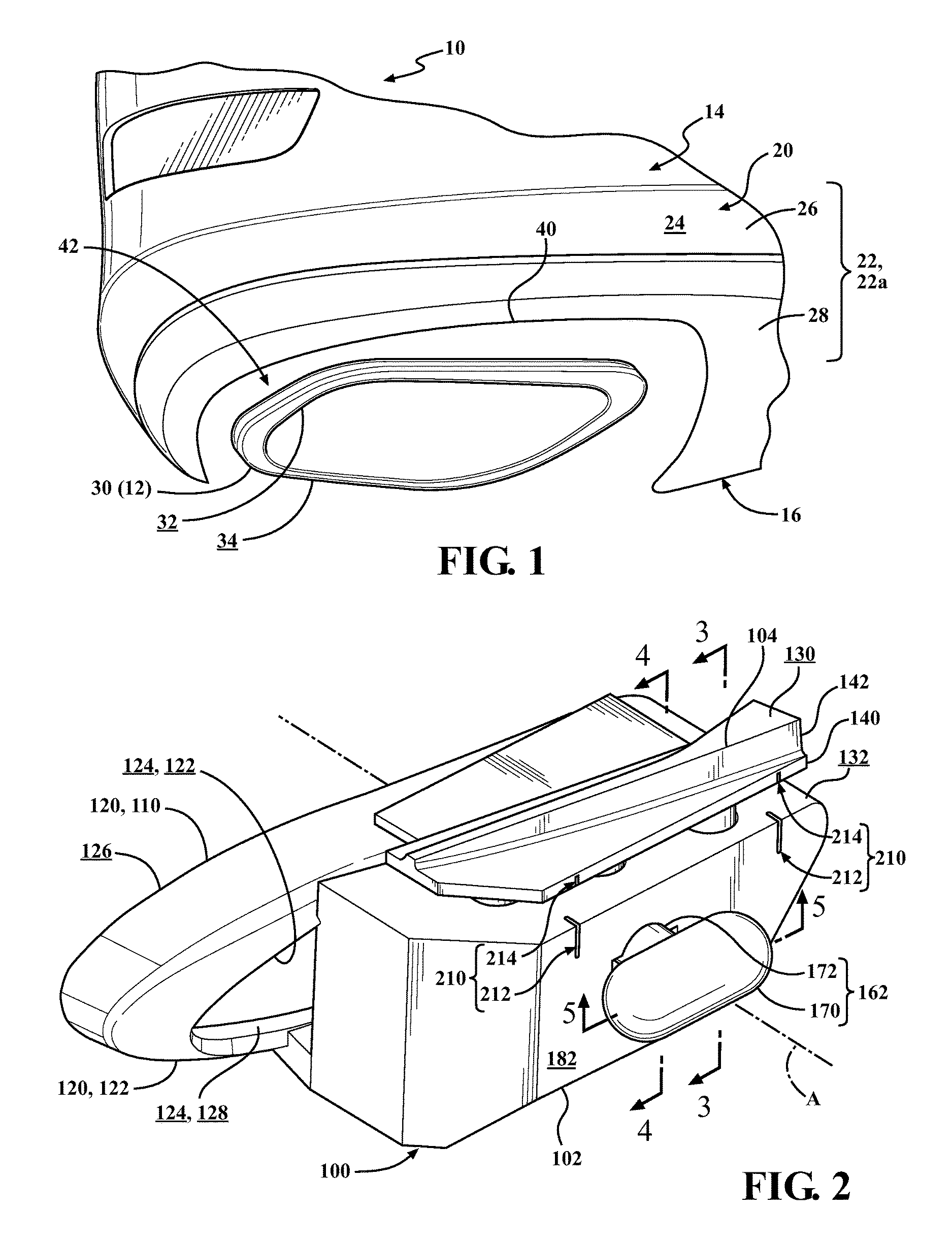
The embodiments disclosed herein relate to the assessment of gaps between exterior components in vehicles. In vehicles equipped with exhaust systems for their engines, the culminations of the exhaust systems are often represented by one or more exterior exhaust elements. In many of these vehicles, each exterior exhaust element is spaced from the edge of an exterior body panel, leaving a gap between the exterior exhaust element and the edge of the exterior body panel. Operators sometimes assess this gap, and either confirm it if it is satisfactory, or adjust and reassess it if it is not. The operator's assessment and ultimate confirmation of this gap can be performed during the vehicle's assembly, or after the vehicle's assembly, for example, as a part of outflow testing for the vehicle. Vehicle manufactures, among others, may desire to facilitate the operator's assessment of this gap. Disclosed herein are embodiments of a gap assessment tool. In one aspect, a gap assessment tool includes a base and an edge probe. The base fits to an exterior exhaust element of a vehicle, and includes the first of a pair of defined measurement locations. The edge probe is supported by the base for movement to an extended position in which, with the base fitted to the exterior exhaust element, the edge probe contacts an edge of an exterior body panel of the vehicle spaced from the exterior exhaust element, and includes the second of the pair of defined measurement locations. With the base fitted to the exterior exhaust element, and with the edge probe moved to the extended position and contacting the edge of the exterior body panel, a measurement between the pair of defined measurement locations is indicative of a part of a gap between the exterior exhaust element and the edge of the exterior body panel. In another aspect, a gap assessment tool includes a base, an edge probe, an actuator and a handle. The base includes an adaptor that collars an exterior exhaust element of a vehicle to attach the base, via the adaptor, to the exterior exhaust element, and the first of a pair of defined measurement locations. The edge probe is supported by the base for movement to an extended position in which, with the base fitted and attached to the exterior exhaust element, the edge probe contacts an edge of an exterior body panel of the vehicle spaced from the exterior exhaust element, and includes the second of the pair of defined measurement locations. The actuator is between the base and the edge probe, and biases the edge probe away from the base in the direction of the edge probe's movement to the extended position to actuate the edge probe's movement to the extended position. The handle selectively operates the actuator. With the base attached, via the adaptor, to the exterior exhaust element, and with the edge probe moved to the extended position and contacting the edge of the exterior body panel, a measurement between the pair of defined measurement locations is indicative of a part of a gap between the exterior exhaust element and the edge of the exterior body panel. These and other aspects will be described in additional detail below. The various features, advantages and other uses of the present embodiments will become more apparent by referring to the following detailed description and drawings in which: This disclosure teaches a gap assessment tool that facilitates an operator's assessment of the gap, in a vehicle, between an exterior exhaust element and an edge of an exterior body panel spaced from the exterior exhaust element. More specifically, the gap assessment tool installs between the exterior exhaust element and the edge of the exterior body panel, and provides the operator with one or more pairs of defined measurement locations that respectively correspond to different parts of the gap. With the gap assessment tool, an operator can take easy, accurate and repeatable measurements indicative of the different parts of the gap between the respective pairs of defined measurement locations. A vehicle 10 equipped with an exhaust system 12 for its engine is shown in In the vehicle 10, with the exhaust system 12 culminating at the rear end of the vehicle 10, these exterior body panels 22 are represented in The exhaust system 12 is suspended from the underbody 16 of the vehicle 10, and is routed along the underbody 16 from the engine of the vehicle 10 to the environment surrounding the vehicle 10. The components of the exhaust system 12 may include one or more catalytic converters, resonators and mufflers, and intermediary exhaust pipes between these components, as well as one or more tailpipes that extend from a penultimate downstream component, typically a muffler, and culminate the exhaust system 12. In the vehicle 10, the culmination of the exhaust system 12 is represented by one or more exterior exhaust elements 30 adjacent the exterior surface 24 of the body 14 at or near the juncture between the body 14 and the underbody 16. As pointed out above, in the vehicle 10, the exhaust system 12 culminates at the rear end of the vehicle 10. Thus, in the vehicle 10, the exterior exhaust element 30 is adjacent the exterior surface 24 of the body 14 defined by the exterior body panel 22 The exterior exhaust element 30 is included in or otherwise associated with the exhaust system 12. The exterior exhaust element 30 may be the terminal end of a tailpipe that culminates the exhaust system 12, for instance, or an exhaust baffle, an exhaust tip or other exhaust finisher, whether attached at the terminal end of a tailpipe that culminates the exhaust system 12, or attached otherwise to the vehicle 10, for example to an exterior body panel 22, such as the exterior body panel 22 The exterior exhaust element 30 is generally tubular, with an inside surface 32 and an outside surface 34. As shown, the exterior exhaust element 30 includes a single tube incorporating the entirety of its inside surface 32 and its outside surface 34. In alternative examples, the exterior exhaust element 30 could, for instance, include multiple tubes. In these alternative examples of the exterior exhaust element 30, the multiple tubes will incorporate respective portions of its total inside surface 32 and its total outside surface 34. As shown, the exterior exhaust element 30 is adjacent the exterior surface 24 of the body 14 defined by the exterior body panel 22 For the illustrated exterior body panel 22 The edge 40 of the exterior body panel 22 It will be understood that the gap 42 between the exterior exhaust element 30 and the edge 40 of the exterior body panel 22 An operator may assess the gap 42, for instance, by taking direct measurements of one or more parts of the gap 42. However if, for instance, the exterior exhaust element 30 sits forward or rearward from the edge 40 of the exterior body panel 22 A gap assessment tool 100 is shown in The gap assessment tool 100 is generally configured for installation between the exterior exhaust element 30 and the edge 40 of the exterior body panel 22 The base 102 can be configured for fitment to the exterior exhaust element 30 in any manner supportive of the overall installation of the gap assessment tool 100 between the exterior exhaust element 30 and the edge 40 of the exterior body panel 22 In the illustrated example of the base 102, the primary engagement portion 110 defines a primary engagement surface 112 sized and shaped for positioning in engagement against the outside surface 34 of the exterior exhaust element 30 along a circumferential portion of the exterior exhaust element 30 where its outside surface 34 opposes the edge 40 of the exterior body panel 22 In these or other examples of the primary engagement portion 110, the primary engagement surface 112 defined by the primary engagement portion 110 may, as shown, be sized and shaped to generally match the contour of the outside surface 34 of the exterior exhaust element 30 or the inside surface 32 of the exterior exhaust element 30, as the case may be, for positioning in continuous engagement against them. Alternatively, the primary engagement surface 112 defined by the primary engagement portion 110 could, for example, be sized and shaped for positioning in engagement at one or more discrete points against the outside surface 34 of the exterior exhaust element 30 or the inside surface 32 of the exterior exhaust element 30, as the case may be. Beyond being configured for fitment to the exterior exhaust element 30, the base 102 can optionally be configured for attachment to the exterior exhaust element 30 in any manner supportive of the overall installation of the gap assessment tool 100 between the exterior exhaust element 30 and the edge 40 of the exterior body panel 22 As shown, the base 102 includes an adaptor 120 with an auxiliary engagement portion 122 configured for positioning in attaching engagement with the exterior exhaust element 30. In the illustrated example of the base 102, both the primary engagement portion 110 and the auxiliary engagement portion 122 are included in the adaptor 120, and the auxiliary engagement portion 122 is configured for positioning in attaching engagement with the exterior exhaust element 30 in collaboration with the positioning of the primary engagement portion 110 in engagement against the exterior exhaust element 30 in opposition to the contact with the edge 40 of the exterior body panel 22 The adaptor 120 may, as shown, be generally tubular and extend along the axis A of the base 102, with an inside surface 124 and an outside surface 126. The inside surface 124 of the adaptor 120 is sized and shaped for positioning in engagement against the outside surface 34 of the exterior exhaust element 30, configuring to adaptor 120 to, in use, collar the exterior exhaust element 30 to fit and attach the base 102, via the adaptor 120, to the exterior exhaust element 30 and to align the axis A of the base 102 in parallel with the exterior exhaust element 30. According to this example of the base 102, the inside surface 124 of the adaptor 120 incorporates the primary engagement surface 112 defined by the primary engagement portion 110 which, as described above, is sized and shaped for positioning in engagement against the outside surface 34 of the exterior exhaust element 30 along a circumferential portion of the exterior exhaust element 30 where its outside surface 34 opposes the edge 40 of the exterior body panel 22 According to alternative examples of the base 102 with the primary engagement surface 112 defined by the primary engagement portion 110 sized and shaped for positioning in engagement against the inside surface 32 of the exterior exhaust element 30 along a circumferential portion of the exterior exhaust element 30 opposing that where its outside surface 34 opposes the edge 40 of the exterior body panel 22 In these or other examples of the auxiliary engagement portion 122, the auxiliary engagement surface 128 defined by the auxiliary engagement portion 122 may, as shown, be sized and shaped to generally match the contour of the outside surface 34 of the exterior exhaust element 30 or the inside surface 32 of the exterior exhaust element 30, as the case may be, for positioning in continuous engagement against them. Alternatively, the auxiliary engagement surface 128 defined by the auxiliary engagement portion 122 could, for example, be sized and shaped for positioning in engagement at one or more discrete points against the outside surface 34 of the exterior exhaust element 30 or the inside surface 32 of the exterior exhaust element 30, as the case may be. As shown, the edge probe 104 is configured for contact with the edge 40 of the exterior body panel 22 As shown with additional reference to In the illustrated example of the gap assessment tool 100, the base 102 includes the adaptor 120, as explained above, and the remainder of the base 102 is configured, among other things, to support the edge probe 104 for movement to the extended position E in which the edge probe 104 contacts the edge 40 of the exterior body panel 22 As shown, the movement of the edge probe 104 to the extended position E is radially from the axis A of the base 102 that aligns in parallel with the exterior exhaust element 30 with the installation of the gap assessment tool 100 between the exterior exhaust element 30 and the edge 40 of the exterior body panel 22 The withdrawn position W is generally permissive of the fitment of the base 102 to the exterior exhaust element 30. According to the illustrated example of the gap assessment tool 100, in the withdrawn position W, the edge probe 104 is relatively closer to the ledge 132 in avoidance of interference with the edge 40 of the exterior body panel 22 In the illustrated example of the gap assessment tool 100, the edge probe 104 includes a platform 140 adjacent the ledge 132 of the base 102 and oriented similarly to the ledge 132 transversely to the axis A to face the edge 40 of the exterior body panel 22 As shown with additional reference to It will be understood that, in general, the desire to assess the gap 42 between the exterior exhaust element 30 and the edge 40 of the exterior body panel 22 Furthermore, the guide slots 150 and the complementary guide shafts 152 can optionally be sized to define play between them permissive of a certain amount of deflection of the edge probe 104 from its movement to the extended position E in order to accommodate, for instance, unevenness in the gap 42 between the exterior exhaust element 30 and the edge 40 of the exterior body panel 22 As shown with additional reference to In the illustrated example of the actuator 160, the actuator 160 includes a first magnet 164 positioned against the base 102 and a second magnet 166 positioned against the edge probe 104. In general, in this example of the actuator 160, the movement of the edge probe 104 to the extended position E is realized by the application of a magnetic force that biases the edge probe 104 away from the base 102 in the direction of the movement of the edge probe 104 to the extended position E. This magnetic force is generated by the placement of the first magnet 164 in magnetic opposition to the second magnet 166 in the direction of the movement of the edge probe 104 to the extended position E. Although the placement of the first magnet 164 in magnetic opposition to the second magnet 166 in the direction of the movement of the edge probe 104 to the extended position E could, for instance, be permanent, according to the illustrated example of the gap assessment tool 100 including a handle 162 that selectively operates the actuator 160, this placement is selectively implemented by an operator's manipulation of the handle 162. More specifically, in the illustrated example of the gap assessment tool 100, the second magnet 166 is retentively supported by the edge probe 104. The first magnet 164, on the other hand, is retentively supported by the handle 162, which in turn is supported by the base 102 for selective movement by an operator that, when imparted to the first magnet 164, places the first magnet 164 in magnetic opposition to the second magnet 166 in the direction of the movement of the edge probe 104 to the extended position E. As shown, the handle 162 includes a handle knob 170 arranged at the outside of the base 102 for manipulation by an operator. The handle 162 further includes a handle shaft 172 that, as shown, extends from the handle knob 170. The base 102 defines a handle slot 180, and the handle shaft 172 is supported in the handle slot 180 in rotational engagement permissive of rotation of the handle 162 as a whole. The handle slot 180 may, as shown, open from a front surface 182 of the base 102 opposing the adaptor 120 to arrange the handle knob 170 at the front surface 182 for access by an operator. As shown with additional reference to With reference again to The first magnet 164 and the second magnet 166 may, as shown, be generally cylindrically shaped, although it will be understood that either or both of the first magnet 164 and the second magnet 166 could be otherwise shaped. According to this configuration the actuator 160 and the handle 162, the first magnet 164 can be diametrically magnetized and arranged along the handle shaft 172, normally to the direction of the movement of the edge probe 104 to the extended position E, while the second magnet 166 can be axially magnetized and arranged in the direction of the movement of the edge probe 104 to the extended position E, for instance. Accordingly, as the handle shaft 172 and the remainder of the handle 162 is rotated by an operator's manipulation of the handle knob 170, and this rotation is imparted to the first magnet 164, the first magnet 164 can be rotated into magnetic opposition to the second magnet 166 in the direction of the movement of the edge probe 104 to the extended position E to operate the actuator 160 to actuate the movement of the edge probe 104 to the extended position E. It will be understood that the first magnet 164 may also be rotated out of magnetic opposition to the second magnet 166 in the direction of the movement of the edge probe 104 to the extended position E, allowing for the return movement of the edge probe 104 to the withdrawn position W. Although the actuator 160, the handle 162 and related features of the base 102 and edge probe 104 are illustrated and described with reference to the example where the second magnet 166 is retentively supported by the edge probe 104 and the first magnet 164 is retentively supported by the handle 162, which in turn is supported by the base 102, it will be understood that these teachings are equally applicable in principle to alternative examples where, for instance, the handle 162 is supported by the edge probe 104, with the first magnet 164 retentively supported by the base 102 and the second magnet 166 retentively supported by the handle 162. In general, the gap assessment tool 100 facilitates an operator's assessment of the gap 42 between the exterior exhaust element 30 and the edge 40 of the exterior body panel 22 In the gap assessment tool 100, each pair 210 of defined measurement locations 212 and 214 is divided between the base 102 and the edge probe 104, with the base 102 including the firsts 212 of the pairs 210 of the defined measurement locations 212 and 214, and the edge probe 104 including the seconds 214 of the pairs 210 of the defined measurement locations 212 and 214. With this arrangement, during the installation of the gap assessment tool 100 between the exterior exhaust element 30 and the edge 40 of the exterior body panel 22 The gap assessment tool 100 may, as shown, include two pairs 210 of defined measurement locations 212 and 214, although alternatively the gap assessment tool 100 could, for example, define one pair 210 of defined measurement locations 212 and 214 or more than two pairs 210 of defined measurement locations 212 and 214. In examples of the gap assessment tool 100 including multiple pairs 210 of defined measurement locations 212 and 214, the pairs 210 of defined measurement locations 212 and 214 may, as shown, be spaced from one another about the gap assessment tool 100 to respectively correspond to different parts of the gap 42. As shown with additional reference to In use, the gap assessment tool 100 may reduce or eliminate one, some or all of the difficulties in taking take direct measurements of one or more parts of the gap 42 between the exterior exhaust element 30 and the edge 40 of the exterior body panel 22 The defined measurement locations 212 and 214, for instance, are identifiable features to measure between, which, as a product of their smooth profiles, are otherwise absent in the exterior exhaust element 30 and the edge 40 of the exterior body panel 22 The pairs 210 of defined measurement locations 212 and 214 can additionally, for example, be arranged in a common plane normal to the axis A of the base 102. In this arrangement, with the gap assessment tool 100 installed between the exterior exhaust element 30 and the edge 40 of the exterior body panel 22 According to the illustrated example of the gap assessment tool 100, the measurements between the pairs 210 of defined measurement locations 212 and 214 may be taken, for instance, with an external measurement tool, such as the calipers 220 shown in FIG. 7C. As shown, the base 102 may include the firsts of pairs of landings for an external measurement tool at the firsts 212 of the pairs 210 of defined measurement locations 212 and 214, and the edge probe 104 may include the seconds of the pairs of landings for an external measurement tool at the seconds 214 of the pairs 210 of defined measurement locations 212 and 214 which, for the calipers 220, are structured as landing notches for its inside jaws. The gap assessment tool 100 may also be configured to locate the pairs 210 of defined measurement locations 212 and 214 and the remainder of the gap assessment tool 100 relative to the exterior exhaust element 30 and the edge 40 of the exterior body panel 22 While recited characteristics and conditions of the invention have been described in connection with certain embodiments, it is to be understood that the invention is not to be limited to the disclosed embodiments but, on the contrary, is intended to cover various modifications and equivalent arrangements included within the spirit and scope of the appended claims, which scope is to be accorded the broadest interpretation so as to encompass all such modifications and equivalent structures as is permitted under the law. A gap assessment tool includes a base and an edge probe. The base fits to an exterior exhaust element of a vehicle, and includes the first of a pair of defined measurement locations. The edge probe is supported by the base for movement to an extended position in which, with the base fitted to the exterior exhaust element, the edge probe contacts an edge of an exterior body panel of the vehicle spaced from the exterior exhaust element, and includes the second of the pair of defined measurement locations. With the base fitted to the exterior exhaust element, and with the edge probe moved to the extended position and contacting the edge of the exterior body panel, a measurement between the pair of defined measurement locations is indicative of a part of a gap between the exterior exhaust element and the edge of the exterior body panel. 1. A gap assessment tool, comprising:
a base that fits to an exterior exhaust element of a vehicle, the base including the first of a pair of defined measurement locations; and an edge probe supported by the base for movement to an extended position in which, with the base fitted to the exterior exhaust element, the edge probe contacts an edge of an exterior body panel of the vehicle spaced from the exterior exhaust element, the edge probe including the second of the pair of defined measurement locations, wherein: with the base fitted to the exterior exhaust element, and with the edge probe moved to the extended position and contacting the edge of the exterior body panel, a measurement between the pair of defined measurement locations is indicative of a part of a gap between the exterior exhaust element and the edge of the exterior body panel. 2. The gap assessment tool of the base includes the firsts of multiple pairs of defined measurement locations, the edge probe includes the seconds of the pairs of defined measurement locations, and with the base fitted to the exterior exhaust element, and with the edge probe moved to the extended position and contacting the edge of the exterior body panel, measurements between the pairs of defined measurement locations are indicative of respective different parts of the gap between the exterior exhaust element and the edge of the exterior body panel. 3. The gap assessment tool of the base includes the first of a pair of landings for an external measurement tool at the first of the pair of defined measurement locations, and the edge probe includes the second of the pair of landings for an external measurement tool at the second of the pair of defined measurement locations. 4. The gap assessment tool of the base has an axis that is alignable in parallel with the exterior exhaust element, and the first and the second of the pair of defined measurement locations are arranged in a common plane normal to the axis. 5. The gap assessment tool of 6. The gap assessment tool of 7. The gap assessment tool of the base defines one or more guides slot extending in the direction of the edge probe's movement to the extended position, and the edge probe includes one or more complementary guide shafts supported in respective of the one or more guide slots in sliding engagement permissive of the edge probe's movement to the extended position. 8. The gap assessment tool of an actuator between the base and the edge probe, the actuator actuating the edge probe's movement to the extended position. 9. The gap assessment tool of 10. The gap assessment tool of a handle that selectively operates the actuator. 11. The gap assessment tool of 12. The gap assessment tool of the handle is supported by the base for selective rotation, the actuator includes a first magnet supported by the handle, with the handle imparting its rotation to the first magnet, and a second magnet positioned against the edge probe, and with rotation of the first magnet via rotation of the handle, the first magnet is placed into magnetic opposition to the second magnet in the direction of the edge probe's movement to the extended position to actuate the edge probe's movement to the extended position. 13. A gap assessment tool, comprising:
a base, the base including an adaptor that collars an exterior exhaust element of a vehicle to attach the base, via the adaptor, to the exterior exhaust element, and the first of a pair of defined measurement locations; an edge probe supported by the base for movement to an extended position in which, with the base attached to the exterior exhaust element, the edge probe contacts an edge of an exterior body panel of the vehicle spaced from the exterior exhaust element, the edge probe including the second of the pair of defined measurement locations; an actuator between the base and the edge probe, the actuator biasing the edge probe away from the base in the direction of the edge probe's movement to the extended position to actuate the edge probe's movement to the extended position; and a handle that selectively operates the actuator, wherein: with the base attached, via the adaptor, to the exterior exhaust element, and with the edge probe moved to the extended position and contacting the edge of the exterior body panel, a measurement between the pair of defined measurement locations is indicative of a part of a gap between the exterior exhaust element and the edge of the exterior body panel. 14. The gap assessment tool of the base includes the firsts of multiple pairs of defined measurement locations, the edge probe includes the seconds of the pairs of defined measurement locations, and with the base attached, via the adaptor, to the exterior exhaust element, and with the edge probe moved to the extended position and contacting the edge of the exterior body panel, measurements between the pairs of defined measurement locations are indicative of respective different parts of the gap between the exterior exhaust element and the edge of the exterior body panel. 15. The gap assessment tool of the base includes the first of a pair of landings for an external measurement tool at the first of the pair of defined measurement locations, and the edge probe includes the second of the pair of landings for an external measurement tool at the second of the pair of defined measurement locations. 16. The gap assessment tool of the adaptor is tubular and extends along an axis of the base that is alignable in parallel with the exterior exhaust element with the attachment of the base, via the adaptor, to the exterior exhaust element, and the first and the second of the pair of defined measurement locations are arranged opposite the adaptor in a common plane normal to the axis. 17. The gap assessment tool of 18. The gap assessment tool of the base defines one or more guides slot extending in the direction of the edge probe's movement to the extended position, and the edge probe includes one or more complementary guide shafts supported in respective of the one or more guide slots in sliding engagement permissive of the edge probe's movement to the extended position. 19. The gap assessment tool of 20. The gap assessment tool of the handle is supported by the base for selective rotation, the actuator includes a first magnet supported by the handle, with the handle imparting its rotation to the first magnet, and a second magnet positioned against the edge probe, and with rotation of the first magnet via rotation of the handle, the first magnet is placed into magnetic opposition to the second magnet in the direction of the edge probe's movement to the extended position to actuate the edge probe's movement to the extended position.TECHNICAL FIELD
BACKGROUND
SUMMARY
BRIEF DESCRIPTION OF THE DRAWINGS
DETAILED DESCRIPTION