BULB STRUCTURE
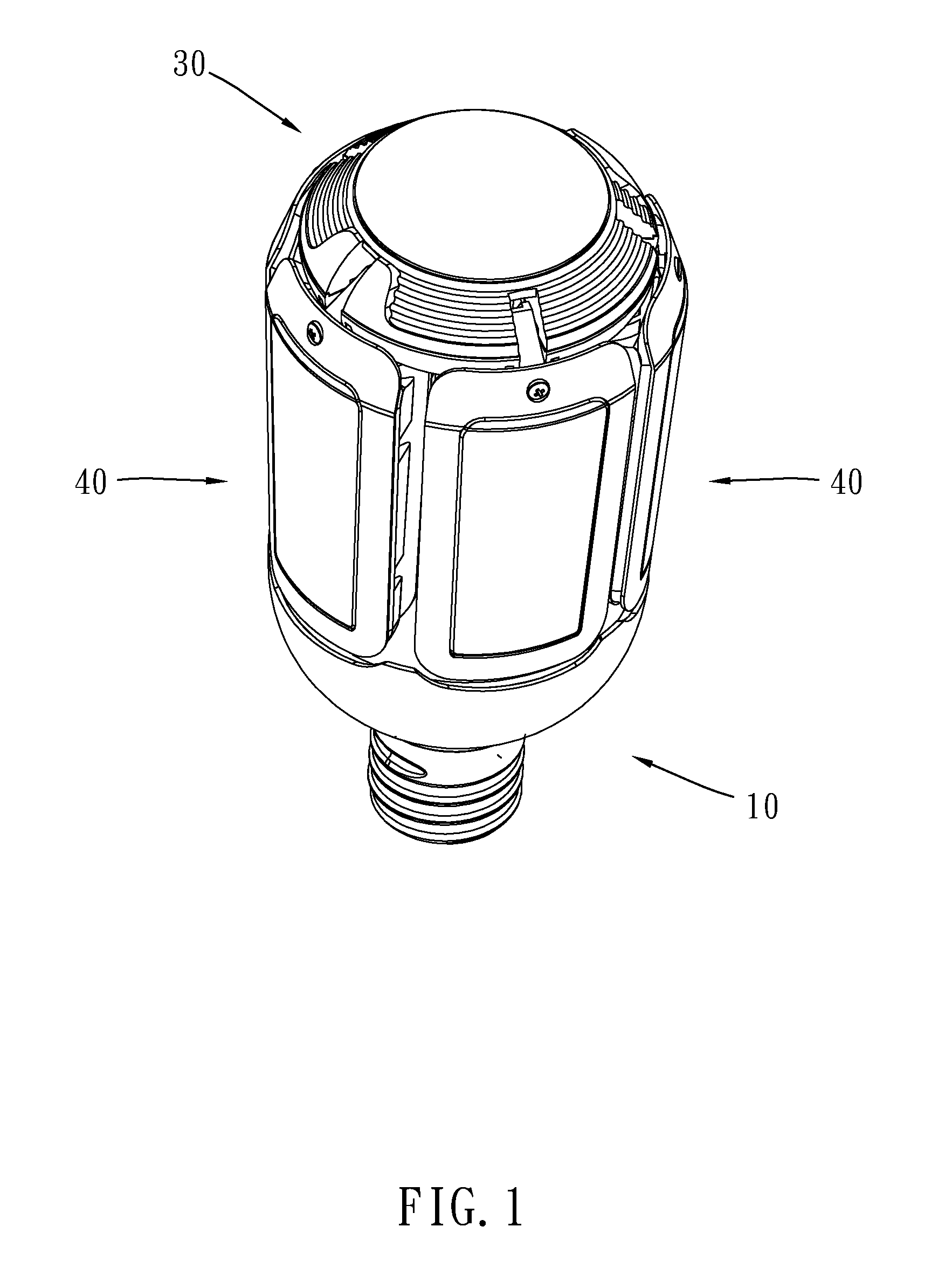
The present invention relates generally to a bulb, and particularly to a bulb structure having spreadable and retractable lamp leaves. A lamp is an important invention of humans. It brings significant convenience to people's lives. As technologies advance day by day, various types of lamps with respective advantages are provided in the market. Lamps including incandescent lamps, fluorescent lamps, halogen lamps, electrodeless lamps, mercury-free lamps, and lighting LEDs, own their optoelectric characteristics, safety properties, environmental protection properties, and price-performance ratios. LEDs have strong potential in lighting applications. Their applications and market share will expand rapidly. As lighting technologies develop, the figure of merit for future lighting is not limited to the lighting range only. The lighting effects, comfort, biological effects, safety, environmental protection, and resource consumption are evaluated as well. LEDs own the advantages of low power consumption and long lifetime. Thereby, no matter in public or domestic lighting, they have started to replace current incandescent lamps and power-saving lamps gradually; the related products of LEDs are also developing prosperously and increasingly. The light emitted by the LED chips in the LED bulb structure according to the prior art is directional. Thereby, other structures or devices are required to scatter the light, so that the LED bulb structure can emit uniform light instead of directional light. Alternatively, a plurality of LED chips can be disposed in a bulb structure at various directions. Consequently, the light paths of the light emitted by the LED chips can encompass the environment uniformly. Nonetheless, the method of changing the light of the LED bulb structure is still limited. In addition, the LED bulb structures according to the prior art are mostly fixed. There are few ways to change the lighting method. The drawback of the light-emitting methods of the LED bulb structure according to the prior art is their fixed configuration, which makes their usage in lighting inflexible. Accordingly, the present invention provides a bulb structure to solve the above drawback according to the prior. An objective of the present invention is to provide a bulb structure, which may change the structure of a lamp for satisfying various lighting ranges. Another objective of the present invention is to provide a bulb structure, which may change the structure of a lamp for improving heat dissipation. The present invention provides a bulb structure, which comprises a bulb base, a pole member, a transmission base, and a plurality of lamp leaves. One end of the pole member is disposed at the bulb base. The transmission base is disposed at the other end of the pole member. The plurality of lamp leaves are disposed pivotally surrounding the transmission base and located surrounding the pole member. The plurality of lamp leaves pivot on the transmission base and move away from the pole member. According to an embodiment, the transmission base further comprises a base, which includes a plurality of first pivot structures. Each first pivot structure includes a pivot groove and two pivot holes. The two pivot holes are located on the two sidewalls of the pivot groove and opposing to each other. Each lamp leaf is disposed pivotally at the transmission base and includes a housing. The housing includes a second pivot structure, which includes a pivot member and two pivot bumps. The two pivot bumps are disposed on both sides of the pivot member and opposing to each other. The pivot member is wedged into the pivot groove. The two pivot bumps are wedged into the two pivot holes, respectively. According to an embodiment of the present invention, each first pivot structure further includes two fixing bumps disposed on the two sidewalls of the pivot groove. Each second pivot structure is disposed pivotally at each first pivot structure and includes a plurality of penetrating holes at the pivot member. The two fixing bumps are wedged into the two openings of one of the plurality penetrating holes, respectively, such that each lamp leaf forms an angle with respect to the base. Each lamp leaf pivots on the base and includes a plurality of angles. The plurality of angles correspond to the locations of the plurality of penetrating holes. According to an embodiment of the present invention, each first pivot structure further includes two fixing bumps disposed on the two sidewalls of the pivot groove. Each second pivot structure is disposed pivotally at each first pivot structure and includes one or more penetrating hole at the pivot member. The two fixing bumps are wedged into the two openings of the one or more penetrating hole, respectively. According to an embodiment of the present invention, each fixing bump further includes a pillar body disposed on the sidewall of the pivot groove and a round head disposed at the pillar body. According to an embodiment of the present invention, the two openings of each penetrating hole include a guiding opening, respectively. According to an embodiment of the present invention, each lamp leaf includes a housing, a base board, and a plurality of LED chips. The housing includes a lamp-leaf accommodating cavity. The base board is disposed in the lamp-leaf accommodating cavity. The plurality of LED chips are disposed on the base board. According to an embodiment of the present invention, each lamp leaf includes a lampshade and a heat sink. The lampshade is disposed over the lamp-leaf accommodating cavity. The heat sink surrounds the periphery of the housing and is located outside the lampshade. According to an embodiment of the present invention, each lamp leaf further includes a housing and a plurality of heat dissipating fins disposed on one side of the housing. According to an embodiment of the present invention, the transmission base further includes a base, a base board, a plurality of LED chips, and a lampshade. The base includes a base accommodating cavity. The base board is disposed in the base accommodating cavity. The plurality of LED chips are disposed on the base board. The lampshade is disposed over the base accommodating cavity and covers the plurality of LED chips. In order to make the structure and characteristics as well as the effectiveness of the present invention to be further understood and recognized, the detailed description of the present invention is provided as follows along with embodiments and accompanying figures. Please refer to One end of the pole member 20 is disposed at the bulb base 10. The transmission base 30 is disposed at the other end of the pole member 20. The plurality of lamp leaves 40 are disposed pivotally surrounding the transmission base 30 and located surrounding the pole member 20. The plurality of lamp leaves 40 pivot on the transmission base 30 and move away from the pole member. Thereby, the bulb structure 1 may change the angle of each lamp leaf 40 freely via the transmission base 30 and thus changing the lighting range of the plurality of lamp leaves 40. According to the present embodiment, the number of the plurality of lamp leaves 40 is five. Nonetheless, the present embodiment does not limit the number of the lamp leaves 40; it may be adjusted according users' requirements. The present embodiment includes one or more structure states (namely, the lighting patterns). As shown in In addition, as shown in The present invention is provided to improve the drawbacks in the prior art. The LED bulb structure according to the prior art is a fixed lighting pattern; its structure is unchangeable. The lighting range of the light emitted by the LED structure is fixed according to the structure design. The lighting range cannot be changed, making applications inflexible. Accordingly, the present invention provides a bulb structure. The advantage of the present invention is that the plurality of lamp leaves 40 may pivot on the transmission base 30. According to user's requirements, the plurality of lamp leaves 40 may spread or close and thus changing the lighting range of the plurality of lamp leaves 40. In addition, according to the design of the bulb structure 1, there is a gap between the plurality of lamp leaves 40 and the bulb base 10. The air in this gap may block heat conduction between the plurality of lamp leaves 40 and the bulb base 10. Hence, the high temperature generated by the LED chips in the plurality of lamp leaves 40 is difficult to influence the temperature of the driving module (not shown in the figure) in the bulb base 10, maintaining normal operations of the driving module as well as extending the lifetime of the bulb structure 1. In addition, when the bulb structure 1 is in the second structure state (spread), it is favorable for the heat dissipation of the plurality of lamp leaves 40 using air convection. Furthermore, the plurality of lamp leaves 40 include two or more structure states, such as the closed state of the first one and the spread state of the second. They may be used for decorating lamps. Please further refer to Please refer to According to the present embodiment, when the number of the one or more penetrating hole 415 is three, the three penetrating holes 415 will be located at the top, center, and bottom of the pivot member 411, respectively. As shown in Besides, please refer to Furthermore, the angle between the edges of the pivot member 411 wedged into the pivot groove 311 is 90 degrees and the two pivot bumps are disposed close to the angle. In addition, the pivot member 411 includes a plurality of penetrating holes 415. The two fixing bumps 315 are wedged into the two openings of one of the plurality of penetrating holes 415, respectively, such that the angle between each lamp leaf 40 and the base 31 is θ. Each lamp leaf 40 may pivot on the base 31 and form a plurality of angles θ with respect to the base 31. The plurality of angles θ correspond to the location of the plurality of penetrating holes 415, respectively. According to the present embodiment, the number of the one or more penetrating hole 415 is three. The three penetrating holes 415 are disposed corresponding to the twp pivot bumps 413. The distances between the pivot bump 413 to the three penetrating holes 415 are identical. Besides, the three penetrating holes 415 are located at the top, bottom, and 45-degree locations. Thereby, when each lamp leaf 40 of the bulb structure 1 pivots on the transmission base 30, it may be turned to the angles of 0 degree (as shown in If the angle between the edges of the pivot member 411 wedged into the pivot groove 311 is less than 90 degrees, the pivot member 411 will not have the corresponding area to dispose the three penetrating holes 415. If the angle between the edges of the pivot member 411 wedged into the pivot groove 311 is greater than 90 degrees, the pivot member 411 will have sufficient areas to dispose the three penetrating holes 415. Although each lamp leaf 40 may pivot over 90 degrees, the lighting range of the bulb structure 1 is limited if this happens, which is disadvantageous to the applications of the bulb structure 1. In addition, the volume of each lamp leaf 40 is increased relatively, resulting in increased overall volume, weight, and cost of the bulb structure 1. Consequently, the most appropriate design of the angle between the edges of the pivot member 411 wedged into the pivot groove 311 should be 90 degrees. Please refer to Please refer to Please refer to Please refer to To sum up, the bulb structure according to the present invention may pivot the plurality of lamp leaves by using the transmission base. The present invention includes one or more structure states. According to requirements of users, the plurality of lamp leaves may be adjusted and changed to a spread or a closed state and thus changing the lighting range of the plurality of lamp leaves. In addition, the plurality of lamp leaves and the bulb base are disposed separately for blocking the high temperature generated by the plurality of LED chips in the plurality lamp leaves from being conducted to the driving module in the bulb base and thus maintaining normal operations of the driving module in the bulb base. Besides, the plurality of lamp leaves in the spread state may facilitate heat dissipation by improving air convection. Furthermore, the spread and close states of the plurality of lamp leaves may be used for decorating the lamp. Accordingly, the present invention conforms to the legal requirements owing to its novelty, nonobviousness, and utility. However, the foregoing description is only embodiments of the present invention, not used to limit the scope and range of the present invention. Those equivalent changes or modifications made according to the shape, structure, feature, or spirit described in the claims of the present invention are included in the appended claims of the present invention. The present invention relates to a bulb structure, which comprises a bulb base, a pole member, a transmission base, and a plurality of lamp leaves. One end of the pole member is disposed at the bulb base. The transmission base is disposed at the other end of the pole member. The plurality of lamp leaves are disposed pivotally surrounding the transmission base and located surrounding the pole member. The plurality of lamp leaves pivot on the transmission base and move away from the pole member. The bulb structure according to the present invention includes two lighting patterns. The lamp leaves may spread or close. Thereby, different lighting ranges may be provided. 1. A bulb structure, comprising:
a bulb base; a pole member, having one end disposed at said bulb base; a transmission base, disposed at the other end of said pole member; and a plurality of lamp leaves, disposed pivotally surrounding said transmission base and located surrounding said pole member, and pivoting on said transmission base and moving away from said pole member. 2. The bulb structure of said transmission base further includes a base, wherein said base includes a plurality of first pivot structures; each said first pivot structure includes a pivot groove and two pivot holes; and said two pivot holes are located on the two sidewalls of said pivot groove and opposing to each other; and each said lamp leaf is disposed pivotally at said transmission base and includes a housing, wherein said housing includes a second pivot structure including a pivot member and two pivot bumps; said two pivot bumps are disposed on both sides of said pivot member and opposing to each other; said pivot member is wedged into said pivot groove; and said two pivot bumps are wedged into said two pivot holes, respectively. 3. The bulb structure of each said first pivot structure further includes two fixing bumps disposed on the two sidewalls of said pivot groove; and each said second pivot structure is disposed pivotally at each said first pivot structure and includes a plurality of penetrating holes at said pivot member, wherein said two fixing bumps are wedged into the two openings of one of said plurality penetrating holes, respectively, such that each said lamp leaf forms an angle with respect to said base; and each said lamp leaf pivots on said base and includes a plurality of angles corresponding to the locations of said plurality of penetrating holes. 4. The bulb structure of each said first pivot structure further includes two fixing bumps disposed on the two sidewalls of said pivot groove; and each said second pivot structure is disposed pivotally at each said first pivot structure and includes one or more penetrating hole at said pivot member, wherein said two fixing bumps are wedged into the two openings of said one or more penetrating hole, respectively. 5. The bulb structure of a pillar body, disposed on the sidewall of said pivot groove; and a round head, disposed at said pillar body. 6. The bulb structure of 7. The bulb structure of a housing, having a lamp-leaf accommodating cavity; a base board, disposed on said lamp-leaf accommodating cavity; and a plurality of light-emitting diode chips, disposed on said base board. 8. The bulb structure of a lampshade, disposed over said lamp-leaf accommodating cavity; and a heat sink, surrounding said housing, and located outside said lampshade. 9. The bulb structure of a housing; and a plurality of heat dissipating fins, disposed on one side of said housing. 10. The bulb structure of a base, having a base accommodating cavity; a base board, disposed in said base accommodating cavity; a plurality of light-emitting diode chips, disposed on said base board; and a lampshade, disposed over said base accommodating cavity, and covering said plurality of light-emitting diode chips.FIELD OF THE INVENTION
BACKGROUND OF THE INVENTION
SUMMARY
BRIEF DESCRIPTION OF THE DRAWINGS
DETAILED DESCRIPTION