SHOVEL
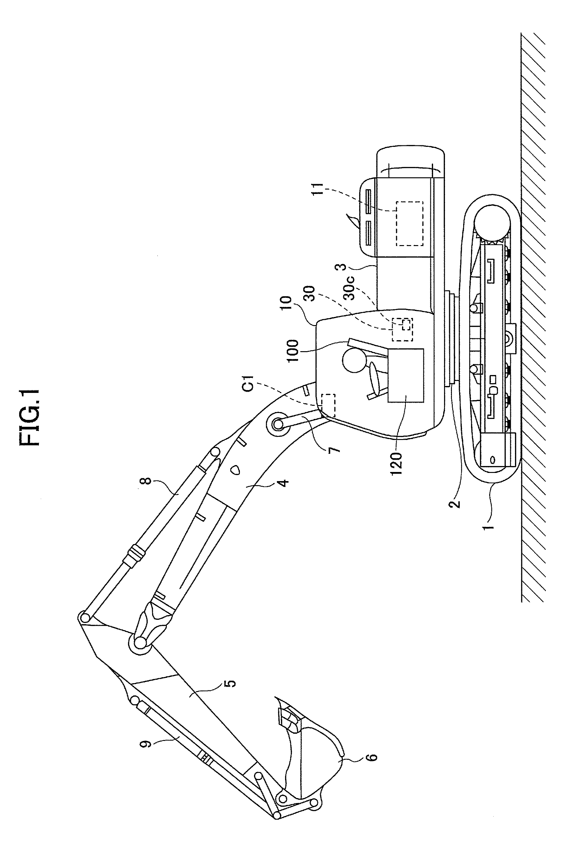
This application is a continuation application filed under 35 U.S.C. 111(a) claiming the benefit under 35 U.S.C. 120 and 365(c) of a PCT International Application No. PCT/JP2016/058437 filed on Mar. 17, 2016, which is based upon and claims the benefit of priority of the prior Japanese Patent Application No. 2015-058709 filed on Mar. 20, 2015, the entire contents of which are incorporated herein by reference. The present invention generally relates to a shovel, in which a target set revolution speed of an engine can be changed. There is a shovel having an auto idling function, by which the revolution speed of an engine is automatically decreased (switching to an idling running operation) when a no-operation state continues in the construction machine. Switching to the idling running operation in the auto idling function is determined whether the no-operation state continues for a predetermined time. Determination of whether the shovel is in the no-operation state can be done using a mechanical switch or a sensor. For example, it is possible to determine the no-operation state, for example, in a case where the position of an operation lever is detected by a sensor and the operation lever is at an operated position (a fallen position). Alternatively, the pilot pressure generated in response to the operation of the operation lever is detected to know the no-operation state. In the auto idling function, while the engine is performing an idling running operation, an operation lever is determined to be operated, and thereafter a control of increasing the engine revolution speed to a revolution speed for an ordinary running operation is performed. However, the engine revolution speed does not instantaneously increase, and a certain time duration is required for the engine revolution speed to reaches a revolution speed necessary for driving. Therefore, there may be a drawback that the shovel is not operated to perform an ordinary speed and power until the engine revolution speed becomes the ordinary revolution speed for the running operation. An object of the embodiment of the present invention is to provide a shovel that can determine whether there exists an operation to operation components before the operation components are operated to rapidly control the engine revolution speed. According to the embodiment, there is provided a shovel enabled to set an engine revolution speed to a plurality of revolution speeds including a revolution speed for a running operation and a revolution speed for an idling running operation that is lower than the revolution speed for the running operation includes an engine provided as a driving source of the shovel, an operating part configured to be driven by a driving force of the engine, an operation component configured to operate the operating part, a detecting device configured to detect a position of a movable portion of an operator and a position of the operation component, an operation determining part configured to determine a positional relationship between the movable portion of the operator and the operation component, and a control part configured to set the engine revolution speed of the engine based on the positional relationship between the movable portion of the operator and the operation component that is determined by the operation determining part. According to the embodiment of the present invention, it is possible to previously determine whether the operation components are operated based on a captured image of the operation components to rapidly control the engine revolution speed. Embodiments of the present invention are described with reference to figures. The boom 4, the arm 5, and the bucket 6 form a drilling attachment as an example of the attachment. The boom 4, the arm 5, and the bucket 6 are hydraulically driven by a boom cylinder 7, an arm cylinder 8, and a bucket cylinder 9, respectively. A cabin 10 as a driver's cabin is installed in the upper-part swiveling body 3. An engine 11 as a power source of the shovel is installed on a back side of the cabin 10 of the upper-part swiveling body 3. The engine 11 is an internal combustion engine such as a diesel engine. A console 120 provided with a driver's seat 100 and an operation lever is installed inside the cabin 10. Further, a controller 30 and a camera C1 are installed inside the cabin 10. The controller 30 is a control device for performing a drive control of the shovel. Within the embodiment, the controller 30 is formed by an arithmetic processing device including a central processing unit (CPU) and a memory 30 The camera C1 in installed on an upper side of the console 120, captures an image of the operation lever and the vicinity of the operation lever, and supplies image information including the captured image to the controller 30. The controller 30 recognizes the operation lever and a hand of an operator in the image information obtained from the camera C1, and presumes or determines the operation if the operation lever from a recognized result. The drive system of the shovel includes the engine 11, a regulator 13, a main pump 14, a pilot pump 15, a control valve 17, an operation device 26, pressure sensors 29 The engine 11 is driven and controlled by an engine control unit (ECU) 74. The engine 11 is a driving source of the shovel. An output shaft of the engine 11 is connected to an input shaft of the main pump 14 and an input shaft of the pilot pump 15. The main pump 14 and the pilot pump 15 are driven by power force of the engine 11 so as to generate hydraulic pressure. The main pump 14 supplies a high-pressure operating oil to the control valve 17 through the high-pressure hydraulic line 16. This main pump 14 may be a swash plate type variable displacement hydraulic pump. The regulator 13 is a device for controlling a discharge quantity from the main pump 14. The regulator 13 adjusts a swash plate inclination angle of the main pump 14 in response to a discharge pressure of the main pump 14, a control signal from the controller 30, or the like. Said differently, the discharge quantity of the operating oil from the main pump 14 is controlled by the regulator 13. The pilot pump 15 supplies the operating oil to various hydraulic pressure controlling apparatuses through a pilot line 25. The pilot pump 15 may be, for example, a fixed displacement type hydraulic pump. The control valve 17 is a hydraulic pressure control device that controls a hydraulic system of the shovel. The control valve 17 selectively supplies the operating oil discharged from the main pump 14 to the boom cylinder 7, the arm cylinder 8, the bucket cylinder 9, a left side hydraulic traveling motor 1A, a right side hydraulic traveling motor 1B, and a hydraulic swiveling motor 2A. The operation device 26 is used to operate various hydraulic actuator including various cylinders 7 to 9, hydraulic traveling motors 1A and 1B, and various hydraulic actuators including the hydraulic swiveling motor 2A. Within the embodiment, the operation device 26 includes a right and left pair of levers 26A and 26B (the operation components) for moving the boom 4 up and down, opening and closing the bucket 6, and operating swiveling of the upper-part swiveling body 3 and a pair of pedals 26C and 26D (the operation components) for operating traveling of the lower-part traveling body 1. The operation device 26 is connected to the control valve 17 through a hydraulic line 27. The operation device 26 is connected to pressure sensors 29 The controller 30 is a control device for controlling the shovel. Within the embodiment, the controller 30 is formed by a computer including a central processing unit (CPU), a random access memory (RAM), a read only memory (ROM). Further, the controller 30 reads a program corresponding to various functional elements from the ROM, loads the read program onto the RAM, and causes processes corresponding to the various functional elements to be executed by the CPU. Further, the controller 30 detects the operation contents (e.g., an existence of a lever operation, a direction of operating a lever, a lever operation quantity, or the like) of the operation device 26 based on the outputs from the pressure sensors 29 As described, the engine 11 is controlled by the ECU 74. Various data indicating the state of the engine 11 are always sent to the controller 30. The controller 30 accumulates these various data in the temporarily memory unit (a memory) 30 Data of a coolant temperature is supplied from a water temperature sensor 11 An oil temperature sensor 14 The operation device 26 includes pressure sensors 29 Further, the shovel according to the embodiment includes an engine revolution speed adjusting dial 75 provided inside the cabin 10. The engine revolution speed adjusting dial 75 adjusts the revolution speed of the engine. Specifically, the engine revolution speed adjusting dial 75 is configured to switch the engine revolution speed to multiple stages of four or greater stages including an SP mode, an H mode, an A mode, and an idling mode. Data indicating a setup state of the engine revolution speed adjusting dial 75 are always supplied to the controller 30. The SP mode is the revolution speed mode selected in a case where priority is given to a work rate, and uses the highest engine revolution speed (the revolution speed for the running operation). The H mode is the revolution speed mode selected in a case where both of the work rate and the fuel consumption are satisfied, and uses the second highest engine revolution speed (the revolution speed for the running operation). The A mode is the revolution speed mode selected in a case where the shovel runs with a low noise while priority is given to the fuel consumption are satisfied, and uses the third highest engine revolution speed (the revolution speed for the running operation). The idling mode is the revolution speed mode selected in a case where the engine is in an idling state, and uses the lowest engine revolution speed (the revolution speed for the running operation). The revolution speed of the engine 11 is constantly controlled to be the engine revolution speed for the revolution speed mode set by the engine revolution speed adjusting dial 75. If a predetermined condition is satisfied as described later, a command value of a set engine revolution speed is output to change the engine revolution speed. Next, referring to The driver's seat 100 is installed inside the cabin 10. The driver's seat 100 includes a seat on which an operator 100 sits and a backrest 104. The driver's seat is a reclining seat, in which the reclining angle of the backrest 104 can be adjusted. Armrests 106 are disposed on both left and right sides of the driver's seat 100. The armrests 106 are supported by the driver's seat 100 so as to be rotatable. When the operator of the shovel leaves the driver's seat 100, the armrest 106 is backward rotated as illustrated in A console 120A and a console 120B are respectively arranged on both left and right sides of the driver's seat 100. The driver's seat 100 and the consoles 120A and 120 The operation lever 26A is disposed on a front side of the left console 120A. The operation lever 26B is disposed on a front side of the right console 120B. The operator sitting down in the driver's seat 100 grabs the operation lever 26A with the left hand of the operator to operate the operation lever 26A and grabs the operation lever 26B with the right hand of the operator to operate the operation lever 26B. Each of the consoles 120A and 120B is supported so as to be rotatable. The operator can adjust the angles of the consoles 120A and 120B to adjust the angles of the operation levers 26A and 26B at their neutral positions. Operation pedals 26C and 26D are disposed on the floor surface on a front side of the driver's seat 100. The operator sitting down on the driver's seat 100 operates the operation pedal 26C with his or her left foot to drive the left side hydraulic traveling motor 1A. The operator sitting down on the driver's seat 100 operates the operation pedal 26D with his or her right foot to drive the right side hydraulic traveling motor 1B. An operation lever 26E upwards extends from a vicinity of the operation pedal 26C. The operator sitting down on the driver's seat 100 grabs the operation lever 26E with his or her left hand to operate the operation lever 26E. Thus, in a manner similar to the operation using the operation pedal 26C, the hydraulic traveling motor 1A can be driven. An operation lever 26F upwards extends from a vicinity of the operation pedal 26D. The operator sitting down on the driver's seat 100 grabs the operation lever 26F with his or her right hand to operate the operation lever 26F. Thus, in a manner similar to the operation using the operation pedal 26D, the hydraulic traveling motor 1B can be driven. A monitor 130 displaying information such as a work condition and a running state of the shovel is disposed at a right front part inside the cabin 10. The operator sitting down on the driver's seat 100 can do the work using the shovel while checking various information displayed on the monitor 130. A gate lock lever 140 is provided on the left side (said differently, a side of an entrance door in the cabin) of the driver's seat 100. By pulling up the gate lock lever 140, the engine 11 is permitted to start and the shovel can be operated. By pulling down the gate lock lever 140, an operating part including the engine 11 cannot start up. Therefore, without a state where the operator sits down on the driver's seat and pulls up the gate lock lever 140, the shovel cannot be operated to secure the safety. Within the embodiment, the camera C1 is attached above the driver's seat inside the cabin 10. The camera C1 is disposed at a position from which images of the operation levers 26A, 26B, 26E, and 26F and the operation pedals 26C and 26D can be captured. The camera C1 may be an image capturing device such as a video camera capturing a motion picture or an image capturing device of continuously capturing images at a constant short time interval. The image captured by the camera C1 is sent to the controller 30 and is used for an engine revolution speed control process described below. The engine revolution speed control process of the embodiment is to control the revolution speed of the engine based on a determination whether the hand or the foot (a movable part of the operator) of the operator is in a state where the operation components such as the operation lever or the operation pedal are ready for the operation. After the engine revolution speed control process illustrated in The operation determining part 30 In step S2, if the operation determining part 30 Said differently, in a case where the hand of the operator is included inside the predetermined area including the operation lever 26A, the controller 30 determines that the operator operates or is to operate the operation lever 26A and causes the revolution speed of the engine 11 to be the revolution speed of the engine 11 for the ordinary running operation. Therefore, for example, when the operator is checking the periphery or the work progress while the operator keeps the operation lever 26 at the neutral position, the revolution speed of the engine 11 is kept to be the revolution speed of the engine 11 for the work. Accordingly, if the operator immediately operates the operation lever 26A, it is unnecessary to recover the engine revolution speed from the revolution speed for the idle run to the revolution speed for the work and the work can be rapidly reopened. Referring to In a case where the engine revolution speed control process according to this embodiment is not conducted, the ordinary auto idling function works. Therefore, the revolution speed of the engine 11 is set to be an idling revolution speed after the time t1. Therefore, the engine revolution speed abruptly decreases as indicated by the dotted line illustrated in On the other hand, in a case where an engine revolution speed control process of this embodiment is performed, the revolution speed of the engine 11 is kept to be the revolution speed for the work as indicated by the solid line illustrated in In step S2, if the operation determining part 30 Said differently, in a case where the hand of the operator is not included inside the predetermined area including the operation lever 26A, the controller 30 determines that the operator does not operate or is not intended to operate the operation lever 26A and causes the revolution speed of the engine 11 to be the idling revolution speed. This corresponds to a so-called auto-idling function. With this, for example, a case where the operator does not operate the operation lever 26A and does not conduct the work, the revolution speed of the engine 11 can be automatically decreased to the idling revolution speed so as to decrease a fuel consumption of the engine 11. After the process of step S4, the operation determining part 30 The operation determining part 30 In step S6, if the operation determining part 30 In step S6, if the operation determining part 30 Referring to In a case where the engine revolution speed control process of this embodiment is not performed, the ordinary auto idling function works, and a process of returning the revolution speed of the engine 11 to the revolution speed for the work after a time t4 when the operation of the operation lever 26A is detected after the time t3. Therefore, as indicated by the dotted line illustrated in On the other hand, in a case where the engine revolution speed control process of the above embodiment is performed, the processes of steps S5, S6, and S3 in this order are performed at the time ti when the worker brings the hand to the operation lever 26A to set the revolution speed of the engine 11 to be the revolution speed for the work. Therefore, as indicated by the solid line illustrated in Further, when the work is ceased, the worker separates the hand from the operation lever 26A immediately after returning the operation lever 26A to the neutral position at a time t6. In the case where the engine revolution speed control process is not performed, the operation lever 26A is in a neutral position at the time t6, this state continues until a time t7 after a predetermined time period from the time t6, and thereafter the engine revolution speed is controlled to decrease to the idling revolution speed. Therefore, the engine revolution speed starts to drop at the time t7 the predetermined time after the time t6 as indicated by the dotted line illustrated in On the other hand, in a case where the engine revolution speed control process of this embodiment is performed, the idling revolution speed is immediately set at the time t6. Further, as indicated by the solid line illustrated in Although the engine revolution speed control process related to the operation of only the operation lever 26A has been described, an engine revolution speed control process similar to the above engine revolution speed control process is applicable to an operation to other operation components (the operation lever and the operation pedal). For example, the above engine revolution speed control process may be applied to an operation of the operation lever 26B. Further, the engine revolution speed control process for the operation lever 26A and the engine revolution speed control process for the operation lever 26B may be simultaneously performed. Further, the above engine revolution speed control process may be applied to one or both of the operation pedals 26C and 26D. In this case, an image of a foot of the operator is recognized and an existence of an operation is determined based on the positional relationship between the image of the foot and the pedals 26C and 26D. Further, the above engine revolution speed control process may be applied to one or both of the operation levers 27E and 27F. When the above engine revolution speed control process is applied to multiple operation components, multiple processing results are prevented from competing against each other. For example, in a case where it is determined that any one of the operation components is operated in the process related to the any one of the operation components, the determination related to the other operation components is ignored and the determination that the any one of the operation components is prioritized so as to be used to keep the revolution speed for the work. According to the embodiment of the present invention, it is possible to previously determine whether the operation components are operated based on a captured image of the operation components to rapidly control the engine revolution speed. All examples and conditional language recited herein are intended for pedagogical purposes to aid the reader in understanding the embodiments and the concepts contributed by the inventor to furthering the art, and are to be construed as being without limitation to such specifically recited examples and conditions, nor does the organization of such examples in the specification relate to a showing of superiority or inferiority of the embodiments. Although the shovel has been described in detail, it should be understood that the various changes, substitutions, and alterations could be made hereto without departing from the spirit and scope of the invention. A shovel enabled to set an engine revolution speed to revolution speeds including a revolution speed for a running operation and a revolution speed for an idling running operation that is lower than the revolution speed for the running operation includes an engine provided as a driving source of the shovel, an operating part configured to be driven by a driving force of the engine, an operation component configured to operate the operating part, a detecting device configured to detect a position of a movable portion of an operator and a position of the operation component, an operation determining part configured to determine a positional relationship between the movable portion and the operation component, and a control part configured to set the engine revolution speed of the engine based on the positional relationship between the movable portion and the operation component that is determined by the operation determining part. 1. A shovel enabled to set an engine revolution speed to a plurality of revolution speeds, the plurality of revolution speeds including:
a revolution speed for a running operation, and a revolution speed for an idling running operation that is lower than the revolution speed for the running operation, the shovel comprising: an engine provided as a driving source of the shovel; an operating part configured to be driven by a driving force of the engine; an operation component configured to operate the operating part; a detecting device configured to detect a position of a movable portion of an operator and a position of the operation component; an operation determining part configured to determine a positional relationship between the movable portion of the operator and the operation component; and a control part configured to set the engine revolution speed of the engine based on the positional relationship between the movable portion of the operator and the operation component that is determined by the operation determining part. 2. The shovel according to wherein when the operation determining part determines that the movable portion of the operator is in a position contacting the operation component, the control part continuously sets the engine revolution speed to the revolution speed for the running operation. 3. The shovel according to wherein when the operation determining part determines that the movable portion of the operator is moving toward the operation component in a state where the engine revolution speed is set to the revolution speed for the idling running operation, the control part sets the engine revolution speed to the revolution speed for the running operation. 4. The shovel according to wherein when the operation determining part determines that the movable portion of the operator does not touch the operation component, the control part sets the engine revolution speed to the revolution speed for the idling running operation. 5. The shovel according to wherein the operation component is an operation lever operable by a hand of the operator. 6. The shovel according to wherein the operation component is an operation pedal operable by a foot of the operator. 7. The shovel according to wherein the detecting device is an image capturing device configured to capture an image of the operation component and a vicinity of the operation component, and wherein the operation determining part determines whether the operation component is operated using the captured image captured by the image capturing device.CROSS-REFERENCE TO RELATED APPLICATIONS
BACKGROUND OF THE INVENTION
1. Field of the Invention
2. Description of the Related Art
SUMMARY OF THE INVENTION
BRIEF DESCRIPTION OF THE DRAWINGS
DETAILED DESCRIPTION OF EMBODIMENTS