VOLUME PUMP
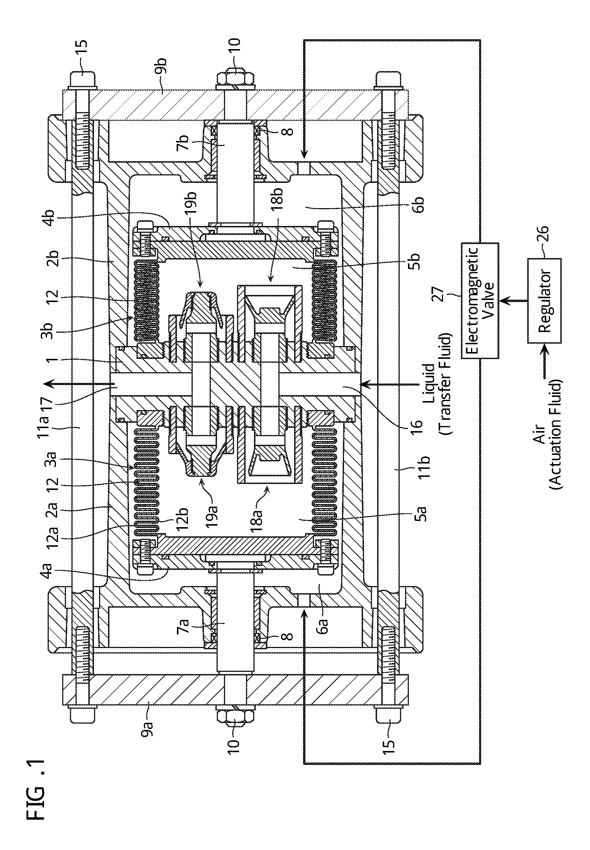
The present invention relates to a volume pump that transfers a transfer fluid by changing a volume of an inside of a pump chamber by a deformable member such as a bellows or a diaphragm. There is known a volume pump that transfers a transfer fluid by changing a volume of an inside of a pump chamber by a deformable member such as a bellows or a diaphragm. In this kind of volume pump, a suction valve is provided between a suction port and the pump chamber of the pump, and a discharge valve is provided between a discharge port and the pump chamber of the pump. Now, for example, Patent Document 1 listed below discloses a volume pump having a suction valve and a discharge valve that include: a cylindrical valve seat; and a valve body that slides along an inner wall of this cylindrical valve seat. Moreover, Patent Document 2 listed below discloses a volume pump having a suction valve and a discharge valve that include: a cylindrical valve seat; and a spherical valve body that slides along an inner wall of this valve seat. [Patent Document 1] JP 2012-211512 A [Patent Document 2] JP 2006-200429 A In both of the above-mentioned Patent Documents 1 and 2, the suction valve and the discharge valve have a sliding portion, and particles generated in this portion sometimes get mixed into the fluid. The present invention was made in view of this kind of problem, and has an object of providing a volume pump capable of preventing particles generated from a sliding portion being mixed into a fluid. A volume pump according to one aspect of the present invention is a volume pump that transfers a transfer fluid by expanding and contracting a bellows. This volume pump includes: the bellows that is disposed so as to be capable of expanding and contracting, and has a bottomed cylindrical shape forming a pump chamber on its inside; a suction valve provided on a suction side of the pump chamber to guide the transfer fluid into the pump chamber; and a discharge valve provided on a discharge side of the pump chamber to discharge the transfer fluid from the pump chamber. In addition, the suction valve and the discharge valve each include a valve seat and a valve body. The valve body is configured from a flexible material and has: a fixed section whose positional relationship with the valve seat is fixed; and a valve section that extends in a certain direction between a direction directed from the fixed section to the valve seat and a direction that the transfer fluid moves. That is, in this kind of volume pump, a valve section of a suction valve and a discharge valve is configured from a flexible material, a positional relationship of a valve seat and a fixed portion of the valve section is fixed, and, furthermore, a movable portion of the valve section extends in a certain direction between a direction extending from a valve body to the valve seat and a direction that a fluid moves. Therefore, it is possible to block a flow path by press-contacting the valve seat and the valve body, and it is possible to prevent sliding of the valve seat and the valve body along each other. Therefore, by utilizing this kind of suction valve and discharge valve in a volume pump such as a bellows pump that does not have a sliding portion inside its pump chamber, it is possible to prevent particles generated from the sliding portion from being mixed into the fluid. Moreover, in a volume pump according to one aspect of the present invention, the valve seat of the suction valve is formed in a cylindrical shape projecting toward the pump chamber, and the valve section is formed in substantially a conical shape whose radius becomes larger along a direction that the transfer fluid moves. Moreover, in a volume pump according to one aspect of the present invention, the valve seat of the discharge valve is formed in a cylindrical shape projecting toward the pump chamber, and the valve section is formed in substantially a conical shape whose radius becomes larger along a direction that the transfer fluid moves. When the discharge valve is configured in this way, for example, the discharge valve may further include a valve body fixing member that fixes a positional relationship of the valve seat and the valve body. Moreover, the valve body fixing member may be formed in substantially a circular columnar shape having an axis whose position matches that of the valve seat, project toward the pump chamber, and include in an outer peripheral portion of an end section projecting into the pump chamber a portion fixed to the valve body. Note that “a portion fixed to the valve body” mentioned here refers to a male screw, for example. Moreover, in this case, furthermore, the valve body of the discharge valve may further include an annular section formed in an annular shape having an axis whose position matches that of the valve seat and including in an inner peripheral portion a portion fixed to the valve body fixing member, and the valve section may be formed integrally with the annular section and extend in the certain direction from the annular section. Note that “a portion fixed to the valve body fixing member” mentioned here refers to a female screw, for example. In this case, by configuring the valve body fixing member from a material whose rigidity is higher compared to that of the valve section, for example, it is possible to prevent an axis of the valve body fixing member from bending due to the likes of a vortex occurring in a flow path, and to reduce a possibility that the valve body and the valve seat slide along each other. Moreover, in the case that the valve seat of the discharge valve is formed in a cylindrical shape projecting toward the pump chamber, and the valve section is formed in substantially a conical shape whose radius becomes larger along a direction that the transfer fluid moves, for example, the discharge valve may further include a valve body fixing member that fixes a positional relationship of the valve seat and the valve body. Furthermore, the valve body may have a projecting section that projects toward the valve body fixing member, and a portion fixed to the valve body fixing member may be formed in an outer peripheral portion of the projecting section. A volume pump according to one aspect of the present invention is a volume pump that transfers a transfer fluid by changing a volume of an inside of a pump chamber by a deformable member. This volume pump includes: a suction valve provided on a suction side of the pump chamber to guide the transfer fluid into the pump chamber; and a discharge valve provided on a discharge side of the pump chamber to discharge the transfer fluid from the pump chamber. The suction valve and the discharge valve each include a valve seat and a valve body. The valve body is configured from a flexible material and has: a fixed section whose positional relationship with the valve seat is fixed; and a valve section that extends in a certain direction between a direction directed from the fixed section to the valve seat and a direction in which the transfer fluid moves. A volume pump according to an embodiment of the present invention will be described in detail below with reference to the drawings. The bellows pump is configured as follows. Bottomed cylindrical cylinders 2 Opening ends of the bellows 3 One ends of coaxially extending shafts 7 The coupling plates 9 A suction port 16 and a discharge port 17 of a transfer fluid are provided in the pump head 1 at positions facing side surfaces of the pump. Along with this, suction valves 18 On the other hand, an actuation fluid, for example, air, from an actuation fluid source such as an unillustrated air compressor is respectively limited to a certain pressure by a regulator 26 to be supplied to an electromagnetic valve 27. It is assumed that the actuation chamber 6 Next, the suction valve 18 As shown in The valve body 22 is configured from a flexible material such as a fluororesin, and, as an example, is formed in substantially a circular columnar shape having an axis whose position matches that of the valve seat 21. A screw section (male screw) 221 is formed in an outer peripheral portion of one end of the valve body 22, and the one end of the valve body 22 is screwed into a female screw of the pump head 1 by this screw section 221. In addition, the other end of the valve body 22 has a valve section 222 formed in substantially a conical shape (horn shape) whose radius is larger the further a portion of the valve section 222 is from the pump head 1. In other words, the valve section 222 has substantially a conical shape whose radius becomes larger along a direction that the transfer fluid moves. That is, as shown in When the pump chamber 5 On the other hand, when the pump chamber 5 Next, the discharge valve 19 As shown in The valve body fixing member 32 is formed in substantially a circular columnar shape having an axis whose position matches that of the valve seat 31, as an example. A screw section (male screw) 321 is formed in an outer peripheral portion of one end of the valve body fixing member 32, and the valve body fixing member 32 is screwed into a female screw of the pump head 1 by this screw section 321. In addition, a screw section (male screw) 322 is formed in an outer peripheral portion of the other end of the valve body fixing member 32, and the valve body fixing member 32 is screwed into the valve body 33 by this screw section 322. Furthermore, a discharge flow path 323 that communicates the discharge port 17 of the pump head 1 and a space 34 between the valve seat 31 and the valve body fixing member 32, is formed in the valve body fixing member 32. The valve body 33 is configured from a flexible material such as a fluororesin. Moreover, as an example, the valve body 33 includes an annular section 335 formed in an annular shape having an axis whose position matches that of the valve seat 31 and having formed in an inner peripheral portion a screw section (female screw) 332 (fixed section) screwed into by the screw section 322 of the valve body fixing member 32. That is, the valve body 33 is screwed into the valve body fixing member 32 by this screw section 332. In addition, the valve body 33 configures a valve section 331 formed integrally with this annular section 335 and formed in substantially a conical shape (horn shape) whose radius is larger the closer the pump head 1 is approached. In other words, the valve section 331 has substantially a conical shape whose radius becomes larger along a direction that the transfer fluid moves. That is, as shown in When the pump chamber 5 On the other hand, when the pump chamber 5 That is, in the volume pump according to the present embodiment, the valve section is configured from a flexible material, a positional relationship of the valve seat and a fixed portion of the valve section is fixed, and, furthermore, a movable portion of the valve section extends in a certain direction between a direction extending from the valve body to the valve seat and a direction that the fluid moves. Therefore, it is possible to block a flow path by press-contacting the valve seat and the valve body, and it is possible to prevent sliding of the valve seat and the valve body along each other. Therefore, by utilizing the suction valve and the discharge valve according to the present embodiment in a volume pump such as a bellows pump or a diaphragm pump that does not have a sliding portion inside its pump chamber, it is possible to prevent particles generated from the sliding portion from being mixed into the fluid. Moreover, in the discharge valve 19 In the example shown in Moreover, in the sense of preventing sliding of the valve seat and the valve body along each other, it is also conceivable for the suction valve and the discharge valve to be configured as shown in, respectively, As shown in In addition, as shown in As shown in As shown in Moreover, provided it is a volume pump that does not have a sliding portion in its pump chamber, the present invention may also be applied to a pump other than a bellows pump. For example, a diaphragm pump may be cited as such a volume pump. A volume pump transfers a transfer fluid by expanding and contracting a bellows, and includes: the bellows that is capable of expanding and contracting, and has a bottomed cylindrical shape forming a pump chamber on its inside; a suction valve provided on a suction side of the pump chamber to guide the transfer fluid into the pump chamber; and a discharge valve provided on a discharge side of the pump chamber to discharge the transfer fluid from the pump chamber. The suction valve and the discharge valve each include a valve seat and a valve body. The valve body is configured from a flexible material and has: a fixed section whose positional relationship with the valve seat is fixed; and a valve section that extends in a certain direction between a direction directed from the fixed section to the valve seat and a direction that the transfer fluid moves. 1. A volume pump that transfers a transfer fluid by expanding and contracting a bellows, the volume pump comprising:
the bellows that is disposed so as to be capable of expanding and contracting, and has a bottomed cylindrical shape forming a pump chamber on its inside; a suction valve provided on a suction side of the pump chamber to guide the transfer fluid into the pump chamber; and a discharge valve provided on a discharge side of the pump chamber to discharge the transfer fluid from the pump chamber, the volume pump comprising the suction valve and the discharge valve each comprise a valve seat and a valve body, and the valve body is configured from a flexible material and has: a fixed section whose positional relationship with the valve seat is fixed; and a valve section that extends in a certain direction between a direction directed from the fixed section to the valve seat and a direction that the transfer fluid moves. 2. The volume pump described in the valve seat of the suction valve is formed in a cylindrical shape projecting toward the pump chamber, and the valve section is formed in substantially a conical shape whose radius becomes larger along a direction that the transfer fluid moves. 3. The volume pump described in the valve seat of the discharge valve is formed in a cylindrical shape projecting toward the pump chamber, and the valve section is formed in substantially a conical shape whose radius becomes larger along a direction that the transfer fluid moves. 4. The volume pump described in the discharge valve further comprises a valve body fixing member that fixes a positional relationship of the valve seat and the valve body, and the valve body fixing member is formed in substantially a circular columnar shape having an axis whose position matches that of the valve seat, projects toward the pump chamber, and comprises in an outer peripheral portion of an end section projecting into the pump chamber a portion fixed to the valve body. 5. The volume pump described in the valve body of the discharge valve further comprises an annular section formed in an annular shape having an axis whose position matches that of the valve seat and comprising in an inner peripheral portion a portion fixed to the valve body fixing member, and the valve section is formed integrally with the annular section and extends in the certain direction from the annular section. 6. The volume pump described in the discharge valve further comprises a valve body fixing member that fixes a positional relationship of the valve seat and the valve body, the valve body has a projecting section that projects toward the valve body fixing member, and a portion fixed to the valve body fixing member is formed in an outer peripheral portion of the projecting section. 7. A volume pump that transfers a transfer fluid by changing a volume of an inside of a pump chamber by a deformable member, the volume pump comprising:
a suction valve provided on a suction side of the pump chamber to guide the transfer fluid into the pump chamber; and a discharge valve provided on a discharge side of the pump chamber to discharge the transfer fluid from the pump chamber, the volume pump comprising the suction valve and the discharge valve each comprise a valve seat and a valve body, and the valve body is configured from a flexible material and has: a fixed section whose positional relationship with the valve seat is fixed; and a valve section that extends in a certain direction between a direction directed from the fixed section to the valve seat and a direction that the transfer fluid moves. 8. The volume pump described in the valve seat of the discharge valve is formed in a cylindrical shape projecting toward the pump chamber, and the valve section is formed in substantially a conical shape whose radius becomes larger along a direction that the transfer fluid moves. 9. The volume pump described in the discharge valve further comprises a valve body fixing member that fixes a positional relationship of the valve seat and the valve body, and the valve body fixing member is formed in substantially a circular columnar shape having an axis whose position matches that of the valve seat, projects toward the pump chamber, and comprises in an outer peripheral portion of an end section projecting into the pump chamber a portion fixed to the valve body. 10. The volume pump described in the valve body of the discharge valve further comprises an annular section formed in an annular shape having an axis whose position matches that of the valve seat and comprising in an inner peripheral portion a portion fixed to the valve body fixing member, and the valve section is formed integrally with the annular section and extends in the certain direction from the annular section. 11. The volume pump described in the discharge valve further comprises a valve body fixing member that fixes a positional relationship of the valve seat and the valve body, the valve body has a projecting section that projects toward the valve body fixing member, and a portion fixed to the valve body fixing member is formed in an outer peripheral portion of the projecting section.TECHNICAL FIELD
BACKGROUND ART
PRIOR ART DOCUMENT
Patent Document
DISCLOSURE OF INVENTION
Problem to be Solved by the Invention
Means for Solving the Problem
BRIEF DESCRIPTION OF DRAWINGS
MODE FOR CARRYING OUT THE INVENTION
First Embodiment
Another Configuration Example
DESCRIPTION OF REFERENCE NUMERALS
1 pump head 2a, 2b cylinder 3a, 3b bellows 5a, 5b pump chamber 6a, 6b actuation chamber 11a, 11b coupling shaft 16 suction port 17 discharge port 18a, 18b suction valve 19a, 19b discharge valve 21, 31 valve seat 22, 33 valve body 222, 331 valve section