GLASS PLATE AND GLASS STRUCTURE
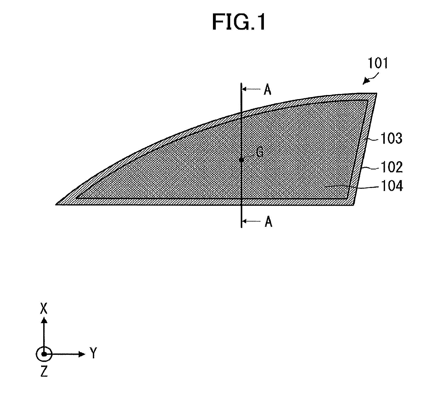
The present application is a continuation application filed under 35 U.S.C. 111(a) claiming benefit under 35 U.S.C. 120 and 365(c) of PCT International Application No. PCT/JP2017/008577 filed on Mar. 3, 2017 and designating the U.S., which claims priority of Japanese Patent Application No. 2016-054013 filed on Mar. 17, 2016. The entire contents of the foregoing applications are incorporated herein by reference. The disclosure herein generally relates to a glass plate and a glass structure. Conventionally, as illustrated in However, there has been a problem, in the configuration disclosed in Japanese Patent No. 3184522, that in order to form facets (inclined surfaces) having great sizes without changing inclination angles to enhance design property, a thickness of the glass plate is required to be thick. Thus, it has been difficult to form inclined surfaces with great sizes. In view of the aforementioned background, the present invention mainly aims at providing a glass plate having inclined surfaces with great sizes. In order to achieve the aim, the present invention provides a glass plate including a first surface and a second surface that is opposite to the first surface, a concave portion being formed on the first surface toward the second surface side with reference to the first surface, and a convex portion being formed on the first surface toward a side opposite to the second surface with reference to the first surface, is provided. According to an aspect of the present invention, a glass plate, on which inclined surfaces with great sizes can be formed, is provided Other objects and further features of embodiments will become apparent from the following detailed description when read in conjunction with the accompanying drawings, in which: In the following, with reference to drawings, a laminated plate according to an embodiment of the present invention will be described. Note that in the following descriptions, as an example, a laminated glass used for a vehicle window will be described. However, the present invention is not limited to this. For example, the laminated plate may be a window glass for building, a plastic glazing, a plastic plate, a plastic decorative board used for an interior or an exterior of a vehicle, and the like. Moreover, the laminated plate may be, as a vehicle window, for example, a front windshield, a slide glass, a fitted window, rear windshield, or a roof glass. Moreover, in the drawings for explaining embodiments, coordinates are defined by arrows in the lower left part in each drawing. An explanation will be provided by using the coordinates as necessary. Moreover, in the specification, “X-direction” is assumed to indicate not only a direction from the tail of the arrow representing X-coordinates to the tip, but also a direction inverted by 180 degrees, from the tip to the tail. “Y-direction” and “Z-direction” are also assumed to indicate not only directions from the tails of the arrow representing Y-coordinates and Z-coordinates, respectively, to the tips, but also the respective directions inverted by 180 degrees from the tips to the tails. In the specification, the X-direction and the Y-direction are also referred to as planar directions, and the Z-direction is also referred to as a plate thickness direction. Moreover, in the specification, terms such as “parallel” or “orthogonal” allow deviations keeping with the effect of the present invention. For example, errors of about ±5° are allowed from parallel or orthogonal positional relationships in a strict sense. Moreover, in the present application, a concave-convex portion or a convex portion is not limited to a glass cut piece. For example, the concave-convex portion or the convex portion may be a shape obtained by performing a press forming for a glass plate heated at a temperature around a softening point using a metallic mold or the like. The concave-convex portion or the convex portion may be formed by reducing a pressure of a concave portion of the metallic mold when the press forming is performed so that a glass enters a deep portion of the concave portion of the metallic mold. Moreover, a molten glass may be poured into a metallic mold and cooled, to prepare the concave-convex portion or the convex portion. The glass plate 101 according to the first embodiment includes a first surface 201, and a second surface 202 that is opposite to the first surface 201. Moreover, in a planar view, the glass plate 101 includes a periphery region 103 along a periphery 102, and an in-plane region 104 that occupies a region inside the periphery region 103. The glass plate 101 includes a concave portion 205 formed on the first surface 201 toward the second surface 202 side with respect to the first surface 201. Moreover, the glass plate 101 includes a convex portion 203 formed on the first surface 201 toward the side of the first surface 201 opposite to the second surface 202. According to the above-described configuration, an inclined surface 206 with a great size can be obtained without increasing a plate thickness of the glass plate 101. Note that the “plate thickness of the glass plate” referred in the specification indicates a distance “B” from the second surface to a tip of the convex portion 203. Next, with reference to A dashed line in A dot-dashed line in In the aforementioned description, two light paths were described as a typical example. For an increase in light having such a light path, for a person, who sees the convex portion 203 and the concave portion 205 from the second surface 202 side, brilliancy of the convex portion 203 and the concave portion 205 increases accordingly. That is, as the sizes of the inclined surfaces 206 The convex portion 203 and the concave portion 205 may be formed in the in-plane region 104 of the glass plate 101, as illustrated in The convex portion 203 and the concave portion 205 may be formed in the periphery region 103 of the glass plate 101. The convex portion 203 and the concave portion 205 may be formed over an entirety of the periphery region 103, or may be formed only in a part of the periphery region 103. Moreover, a plurality of pairs of the convex portion 203 and the concave portion 205 may be foiled. Lengths from the first surface 201 to tips of the plurality of convex portions 203 may be different from each other. Moreover, lengths from the first surface 201 to bottoms of the plurality of concave portions 205 may be different from each other. Shapes of the convex portion 203 and the concave portion 205 may be a shape of a triangular pyramid or a shape of a quadrangular pyramid. The shapes of the convex portion 203 and the concave portion 205 may be, in The tip of the convex portion 203 and the bottom of the concave portion 205 may have tapered shapes. The tapered shape means a shape that is narrowed gradually from the first surface 201 to the tip of the convex portion 203 or the bottom of the concave portion 205. According to the aforementioned configuration, a design property using a refraction and a reflection of light that enters the glass plate 101 can be given to the glass plate 101. The tip portion of the convex portion 203 and the bottom portion of the concave portion 205 may have acute shapes. According to the shapes, the size of the inclined surface 206 can be increased, and the design property of the glass plate 101 can be enhanced. For example, curvature radii of the tip portion of the convex portion 203 and the concave portion 205 are preferably 1 mm or less, more preferably 0.8 mm or less, and further preferably 0.5 mm or less. Moreover, the tip portion of the convex portion 203 and the bottom portion of the concave portion 205 may have planar shapes. According to the shapes, when a single body of the glass plate 101 is bonded to a plate-like body 502 such as a wall surface, where the first surface 201 side of the glass plate 101 is a bonding surface, required bonding areas can be obtained easily. The planar shape of the tip portion of the convex portion 203 may be formed by grinding the tip of the convex portion 203. With reference to the first surface 201, a distance to the tip of the convex portion 203 is preferably 0.1 mm or more, more preferably 0.5 mm or more, and further preferably 1 mm or more. Compared with the first surface 201, differences in the refraction and the reflection of light that enters the glass plate 101 become more evident, and more elaborate design property can be given to the glass plate 101. With reference to the first surface 201, a distance to the tip of the convex portion 203 is preferably 20 mm or less, more preferably 18 mm or less, and further preferably 15 mm or less. Thus, the convex portion 203 becomes difficult to damage. With reference to the first surface 201, a distance to the bottom of the concave portion 205 is preferably 0.1 mm or more, more preferably 0.5 mm or more, and further preferably 1 mm or more. Compared with the first surface 201, differences in the refraction and the reflection of light that enters the glass plate 101 become more evident, and more elaborate design property can be given to the glass plate 101. With reference to the first surface 201, a distance to the bottom of the concave portion 205 is preferably 20 mm or less, more preferably 18 mm or less, and further preferably 15 mm or less. Thus, the convex portion 203 becomes difficult to damage. Moreover, a distance “B” from the second surface 202 to the tip of the convex portion 203 is preferably 10 mm or less, and more preferably 8 mm or less. Thus, the weight of the glass plate 101 is reduced, and the glass plate 101 can be bonded to the plate-like body 502 with a small bonding force. Moreover, a distance “C” from the second surface 202 to the bottom of the concave portion 205 is preferably 70% or more of a distance “D” from the second surface 202 to the first surface 201, more preferably 80% or more, and further preferably 90% or more. When an external force (e.g. pressing force) is applied from the second surface 202 side of the glass plate 101 toward the first surface 201 side of the glass plate 101, the glass plate is deflected as a whole. According to the aforementioned configuration, even if tensile stresses are concentrated on the concave portion 205, the glass plate 101 is difficult to damage. Moreover, at least one of an angle α of the concave portion 205 and an angle β of the convex portion 203, as illustrated in Moreover, the angle α of the concave portion 205 may be different from the angle β of the convex portion 203. Particularly, as illustrated in When the convex portion 203 and the concave portion 205 have optional curvature radii, respectively, the angle α indicates an angle between extensions of the inclined surfaces 206 configuring the concave portion 205 at the bottom of the concave portion 205. Similarly, the angle β indicates an angle between extensions of the inclined surfaces 206 configuring the convex portion 203 at the tip of the convex portion 203. The first surface 201, and surfaces of the convex portion 203 and the concave portion 205 may be polished. According to the treatment, a die mark generated upon shaping using a metallic mold or the like can be removed, and the surface becomes smooth. Thus, diffused reflection is controlled, and thereby the design property is enhanced. The surface roughness of the first surface 201 is preferably 10 μm or less, more preferably 5 μm or less, and further preferably 1 μm or less. As illustrated in The second surface 202 may be a polished surface. When the glass plate 101 is bonded to a wall surface or the like, where the first surface 201 side of the glass plate 101 is a bonding surface, because the second surface 202 is a surface that is touched by a person, the second surface 202 is preferably smooth. Moreover, on the second surface 202, a protection layer, which is difficult to be scratched and to which fingerprints are difficult to adhere, may be formed. The glass plate 101 has a visible light transmissivity (Tv) that is 70% or more, preferably 80% or more, and more preferably 90% or more. When the glass plate 101 is bonded to a wall surface or the like, where the first surface 201 side of the glass plate 101 is a bonding surface, a person, who sees the first surface 201 from the second surface 202 side, can sense a characteristic design property from a light that is refracted or reflected on the first surface 201. The glass plate 101 may be a strengthened glass. The glass plate 101 may be a strengthened glass that is subjected to an air cooling strengthening or a chemical strengthening. In Moreover, in a gap F between the plate-like body 502 and the first surface 201, the adhesive material 501 may exist. According to the configuration, the bonding strength between the glass plate 101 and the plate-like body 502 is enhanced. In The plate-like body 502 or the plate-like body with spacer 701 may be a wall surface of a building, a glazing, a mobile apparatus such as a mobile phone or a smartphone, a vehicular interior member or a vehicular exterior member, or the like. Particularly, in the case where the plate-like body 502 or the plate-like body with spacer 701 is a vehicular interior member or a vehicular exterior member (vehicle decorative member), vibrations from an engine or vibrations from a road surface during a vehicle travelling are applied to the glass plate 101, and the glass structure in which high adhesive strength can be obtained, as illustrated in The present invention relates to a glass plate and a glass structure, and particularly can be preferably used for a vehicle decorative member, an indoor decorative member, or the like. A glass plate includes a first surface and a second surface that is opposite to the first surface. A concave portion is formed on the first surface toward the second surface side with reference to the first surface. A convex portion is formed on the first surface toward a side opposite to the second surface with reference to the first surface. 1. A glass plate comprising a first surface and a second surface that is opposite to the first surface,
wherein a concave portion is formed on the first surface toward the second surface side with reference to the first surface, and wherein a convex portion is formed on the first surface toward a side opposite to the second surface with reference to the first surface. 2. The glass plate according to wherein a distance from the second surface to a tip of the convex portion is 10 mm or less. 3. The glass plate according to wherein the distance from the second surface to the bottom of the concave portion is 70% or more of a distance from the second surface to the first surface. 4. The glass plate according to wherein the concave portion and the convex portion are provided with a coating layer on surfaces. 5. The glass plate according to wherein the coating layer has a reflectance of 70% or more for a light having a wavelength of 380 to 750 nm and being incident at an incident angle of 45′. 6. The glass plate according to wherein at least one of an angle of the convex portion and an angle of the concave portion is within a range of 90°±20°. 7. A glass structure comprising:
the glass plate according to a plate-like body, wherein the convex portion and the concave portion are provided with an adhesive material, and wherein the glass plate is bonded to the plate-like body via the adhesive material. 8. A glass structure comprising;
the glass plate according to a plate like body; and a spacer, wherein the spacer is connected to the first surface and to the plate-like body.CROSS-REFERENCE TO RELATED APPLICATION
BACKGROUND OF THE INVENTION
1. Field of the Invention
2. Description of the Related Art
SUMMARY OF THE INVENTION
Technical Problem
Solution to Problem
Advantageous Effect of Invention
BRIEF DESCRIPTION OF THE DRAWINGS
DETAILED DESCRIPTION OF THE PREFERRED EMBODIMENTS
First Embodiment
INDUSTRIAL APPLICABILITY
REFERENCE SIGNS LIST