HYDRAULIC FLUID DEVICE
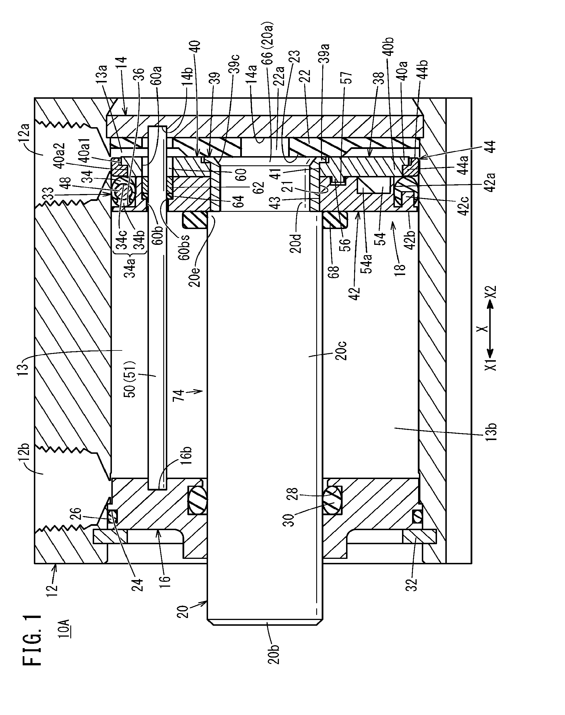
The present invention relates to a fluid pressure device (hydraulic fluid device) provided with a piston. Conventionally, various devices are known as fluid pressure devices provided with pistons. For example, fluid pressure cylinders including pistons displaced by the effect of supplied pressurized fluid are well known as means (actuators) for transporting workpieces and the like. A typical fluid pressure cylinder includes a cylinder tube, a piston disposed inside the cylinder tube so as to be movable in the axial direction, and a piston rod connected to the piston (for example, see Japanese Laid-Open Patent Publication No. 2003-120602 below). A packing composed of an elastic member is mounted on an outer circumferential part of the piston. In such a fluid pressure cylinder, when pressurized fluid such as air is supplied into the cylinder tube, the piston is pushed by the pressurized fluid and displaced in the axial direction. This also causes the piston rod connected to the piston to be displaced in the axial direction. Moreover, a conventional fluid pressure cylinder often includes a magnet installed on an outer circumferential part of a piston and a magnetic sensor attached to an outer surface of a cylinder tube in order to detect the working position of the piston (for example, see Japanese Laid-Open Patent Publication No. 2006-242341). In the conventional technologies including the magnet installed on the outer circumferential part of the piston, the magnet and the packing are disposed at different axial positions on the outer circumferential part of the piston. This leads to an increase in the axial dimension of the piston equipped with the magnet, compared with the piston without the magnet. The present invention has been devised taking into consideration the aforementioned problems, and has the object of providing a fluid pressure device including a piston equipped with a magnet, which prevents axial dimension from increasing. To achieve the above-described object, a fluid pressure device of the present invention includes a body having a slide hole inside the body, a piston unit movable in an axial direction inside the slide hole, and a piston rod protruding from the piston unit in the axial direction. The piston unit includes a packing member and a piston body including a packing mounting groove in which the packing member is mounted. The packing member includes a packing body containing an elastic member and circumferentially extending over an entire circumference of the piston body in a circumferential direction of the piston body, the packing body being provided with a magnet mounting groove having a depth in the axial direction of the piston unit, and a magnet mounted in the magnet mounting groove. According to the fluid pressure device of the present invention adopting the above-described structure, the magnet mounting groove with a groove depth in the axial direction is formed in the packing body, and the magnet is mounted in the magnet mounting groove. Thus, no additional space is required to be left for the magnet at an axial position different from a position where the packing is disposed. Consequently, an increase in the axial dimension of the piston body due to the placement of the magnet is prevented. In the above-described fluid pressure device, the magnet mounting groove may be formed in an area of the packing body that is not subjected to elastic compressive deformation when the packing body receives compressive load at a position between the piston body and an inner surface of the slide hole. The above-described fluid pressure device may further include a rotation restricting mechanism configured to restrict rotation of the piston unit relative to the body. The magnet may be disposed in the packing body over a range less than the entire circumference of the packing body in the circumferential direction. In the above-described fluid pressure device, the rotation restricting mechanism may be a rotation prevention rod extending in the axial direction of the piston unit inside the body and inserted into the piston body. In the above-described fluid pressure device, one of the piston body and the packing member may be provided with an anti-rotation protrusion protruding in the axial direction, the other of the piston body and the packing member may be provided with an anti-rotation recess recessed in the axial direction, and the anti-rotation protrusion may be inserted into the anti-rotation recess. In the above-described fluid pressure device, the piston rod may be rotatable relative to the piston body. In the above-described fluid pressure device, the magnet mounting groove and the magnet each may have a ring shape circumferentially extending over the entire circumference of the packing body in a circumferential direction of the packing body. In the above-described fluid pressure device, the piston body may include a plurality of members including a first piston member and a second piston member, and a combination of at least two members of the plurality of members may define the packing mounting groove. In the above-described fluid pressure device, one or both of the first piston member and the second piston member may be provided with a lightening portion having a depth in the axial direction. In the above-described fluid pressure device, the lightening portion may have a through-hole passing through only one of the first piston member and the second piston member in the axial direction. In the above-described fluid pressure device, the lightening portion may include a plurality of lightening portions disposed at intervals in the circumferential direction. In the above-described fluid pressure device, the first piston member and the second piston member may be castings. The above-described fluid pressure device may be configured as a fluid pressure cylinder, a valve device, a length-measurement cylinder, a sliding table, or a chuck device. According to the fluid pressure device of the present invention, the axial dimension of the piston is prevented from increasing even though the piston equipped with the magnet is adopted. Preferred embodiments of a fluid pressure device according to the present invention will be described in detail below with reference to the accompanying drawings. A fluid pressure cylinder 10A, illustrated in The cylinder tube 12 is a tubular structure composed of, for example, a metal material such as aluminum alloy extending in the axial direction. In this embodiment, the cylinder tube 12 has a hollow cylindrical shape. The cylinder tube 12 has a first port 12 The head cover 14 is a plate-shaped structure composed of, for example, a metal material similar to the material of the cylinder tube 12 and closes the one end portion (end portion located in the direction of the arrow X2) of the cylinder tube 12. The head cover 14 hermetically closes the one end portion of the cylinder tube 12. A first damper 22 is disposed on an inner wall surface 14 The first damper 22 is provided with an expanding portion 23 disposed on the central part of the first damper 22 and expanding toward the rod cover 16 (toward the piston rod 20 and the piston unit 18). In the first damper 22, the thickness of the expanding portion 23 is larger than the thickness of an outer peripheral part disposed radially outside the expanding portion 23. The expanding portion 23 can be brought into abutment with the piston rod 20 and the piston unit 18 when the piston rod 20 and the piston unit 18 are displaced toward the head cover 14. The rod cover 16 is a circular ring-shaped member composed of, for example, a metal material similar to the material of the cylinder tube 12 and closes the other end portion (end portion located in the direction of the arrow X1) of the cylinder tube 12. An outer annular groove 24 is formed in an outer circumferential part of the rod cover 16. An outer sealing member 26 composed of an elastic material is mounted in the outer annular groove 24 in order to seal a gap between the outer circumferential surface of the rod cover 16 and the inner circumferential surface of the slide hole 13. An inner annular groove 28 is formed in an inner circumferential part of the rod cover 16. An inner sealing member 30 composed of an elastic material is mounted in the inner annular groove 28 in order to seal a gap between the inner circumferential surface of the rod cover 16 and the outer circumferential surface of the piston rod 20. The rod cover 16 is locked by a stopper 32 secured to an inner circumferential part of the cylinder tube 12 on the other end side. The piston unit 18 is accommodated inside the cylinder tube 12 (slide hole 13) so as to be slidable in the axial direction and partitions the interior of the slide hole 13 into a first pressure chamber 13 As illustrated in The first piston member 40 is a ring-shaped member with a rod insertion hole 41 on an inner side thereof, and the base end portion 20 A wear ring supporting portion 40 The material of the first piston member 40 includes, for example, metal materials such as carbon steel, stainless steel, and aluminum alloy, and hard resin. In this embodiment, the first piston member 40 is shaped by casting. The first piston member 40 may also be shaped by injection molding. The second piston member 42 is a ring-shaped member with a rod insertion hole 43 in an inner part of the member and is disposed adjacent to the first piston member 40. That is, the first piston member 40 and the second piston member 42 are laminated in the axial direction. In this embodiment, the second piston member 42 is shaped by casting. The second piston member 42 may also be shaped by injection molding. The second piston member 42 includes on the outer circumference a packing supporting portion 42 The piston body 38 is connected to (supported by) the piston rod 20 via a holder 39. The holder 39 is an annular member composed of a hard material including, for example, metal materials such as carbon steel, bearing steel, stainless steel, and aluminum alloy, and hard resin. The holder 39 has a flange portion 39 The insertion shaft portion 20 The first piston member 40 and the second piston member 42 are stacked in the axial direction on the outer circumference of the holder 39. The holder 39 including the flange portion 39 Engagement of the inner circumferences of the first piston member 40 and the second piston member 42 with the annular groove 21 prevents axial movement of the piston unit 18 relative to the piston rod 20. The holder 39 is rotatable with respect to the first piston member 40 and the second piston member 42. Consequently, the piston rod 20 is rotatable relative to the piston unit 18 about the axis of the piston rod 20. As illustrated in An end portion of the rotation prevention rod 51 adjacent to the rod cover 16 is fitted into a fitting groove 16 The insertion hole 60 includes a first insertion hole 60 A bush 62 and a gasket 64 both having an annular shape are disposed inside the second insertion hole 60 The gasket 64 is held between the bush 62 and a stepped portion 60 As illustrated in The first lightening portion 46 As illustrated in As illustrated in In the second piston member 42, abutting surfaces 55 brought into abutment with the end surfaces of the first rims 52 As illustrated in Contrary to the above-described structure, the second piston member 42 may be provided with the positioning protrusions 56, and the first piston member 40 may be provided with the positioning recesses 57. Only one positioning protrusion 56 and the corresponding positioning recess 57 may be provided for the respective piston members. During an assembly process of the piston assembly 74 described below, the positioning protrusions 56 and the positioning recesses 57 prevent the first piston member 40 and the second piston member 42 from rotating relative to each other. As illustrated in The annular projection 40 The packing member 33 includes the packing body 34 composed of an elastic member, and a magnet 48 mounted in the packing body 34. The packing body 34 is a sealing member composed of an elastic body mounted on an outer circumferential part of the second piston member 42. The packing body 34 is mounted in the packing mounting groove 36. The packing body 34 has an annular shape circumferentially extending over the entire circumference of the piston body 38 in the circumferential direction. The material of the packing body 34 includes an elastic material such as rubber and elastomer. The outer diameter of the packing body 34 is larger than the outer diameter of the wear ring 44 when the packing body 34 is in a natural state (when not disposed inside the slide hole 13 and not elastically compressed radially inward) and when the packing body 34 is disposed inside the slide hole 13. The outer circumference of the packing body 34 airtightly or liquid-tightly contacts closely the inner circumferential surface of the slide hole 13 over the entire circumference. The inner circumference of the packing body 34 airtightly or liquid-tightly contacts closely the outer circumferential surface of the second piston member 42 (outer circumferential surface of the packing supporting portion 42 The packing body 34 is provided with a magnet mounting groove 34 The magnet mounting groove 34 The magnet mounting groove 34 The magnet 48 is disposed in the packing body 34 over a range less than the entire circumference in the circumferential direction of the packing body 34. That is, the magnet 48 is disposed only in a part of the packing body 34 in the circumferential direction. The magnet 48 is, for example, a ferrite magnet, a rare earth magnet, or the like. In this embodiment, the magnet 48 has an arc shape extending in the circumferential direction of the packing body 34. The circumferential length of the magnet 48 is set to be substantially identical to the circumferential length of the magnet mounting groove 34 In Magnetic sensors (not illustrated) are attached to the outer surface of the cylinder tube 12 at positions corresponding to both stroke ends of the piston unit 18. The magnetic sensors are disposed on the cylinder tube 12 at circumferential positions corresponding to the circumferential position of the magnet 48. The magnetic sensors detect magnetism generated by the magnet 48 to detect the working position of the piston unit 18. As illustrated in The plurality of anti-rotation protrusions 42 Contrary to the above-described structure, the packing body 34 may be provided with the anti-rotation protrusions 42 The wear ring 44 is a member that prevents the outer circumferential surface of the first piston member 40 from coming into contact with the inner circumferential surface of the slide hole 13 when a large lateral load is applied to the piston unit 18 in directions perpendicular to the axial direction while the fluid pressure cylinder 10A is operating. The wear ring 44 is a circular ring-shaped member mounted on an outer circumferential part of the first piston member 40 so as to surround the outer circumferential part of the first piston member 40. In this embodiment, the wear ring 44 includes a radial portion 44 The wear ring 44 is composed of a low friction material. The frictional coefficient between the wear ring 44 and the inner circumferential surface of the slide hole 13 is smaller than the frictional coefficient between the packing body 34 and the inner circumferential surface of the slide hole 13. Such a low friction material includes, for example, synthetic resins with a low friction property and a high wear resistance such as polytetrafluoroethylene (PTFE) and metal materials (for example, bearing steel). A second damper 68 composed of an elastic member is attached to an end of the piston unit 18 that is remote from the head cover 14 (an end located in the direction of the arrow X1). The second damper 68 may be composed of a material similar to the material of the first damper 22. The second damper 68 has a circular ring shape and is disposed on the outer circumferential surface of the piston rod 20. The second damper 68 is disposed adjoining a side of the second piston member 42 that is located in the direction of the arrow X1. That is, the second damper 68 is stacked on the second piston member 42 in the axial direction. During operation of the fluid pressure cylinder 10A (while the piston unit 18 reciprocates), the second damper 68 may be separate from the second piston member 42. The fluid pressure cylinder 10A may exclude one of the first damper 22 and the second damper 68 or may exclude both of the first damper 22 and the second damper 68. The first damper 22 may be attached to the piston unit 18. The piston rod 20 is a pillar-shaped (cylindrical) member extending in the axial direction of the slide hole 13. The piston rod 20 includes a rod body 20 As illustrated in The piston rod 20 passes through the rod cover 16. A distal end portion 20 The material of the piston rod 20 includes, for example, the material of the first piston member 40 (such as carbon steel). The piston rod 20 may be composed of a material identical to or different from the material of the first piston member 40. Next, an example method of assembling (producing) the piston assembly 74 configured as above will be described. For example, in an assembly process, the second damper 68, the second piston member 42, the packing member 33, the wear ring 44, and the first piston member 40 described above are moved in the axial direction on the piston rod 20, and are then assembled to the piston rod 20. Thus, the piston assembly 74 is obtained. Specifically, in the assembly process, the second damper 68 is first moved toward the distal end portion 20 Next, the second piston member 42 is moved to thereby insert the insertion shaft portion 20 Next, the packing member 33 with the magnet 48 being mounted in the magnet mounting groove 34 When the packing member 33 is attached to the second piston member 42, the anti-rotation protrusions 42 Next, the gasket 64 and the bush 62 are inserted into the second insertion hole 60 Next, the wear ring 44 and the first piston member 40 are sequentially moved in the axial direction of the piston rod 20. This causes the second piston member 42 to be stacked on the first piston member 40 and further causes the wear ring 44 to be mounted on the outer circumferential part of the first piston member 40. In this case, the positioning protrusions 56 provided on the first piston member 40 are inserted into the positioning recesses 57 formed in the second piston member 42. This causes the end surfaces of the first rims 52 The first piston member 40 stacked on the second piston member 42, the second piston member 42, and the wear ring 44 disposed on the outer circumference of the first piston member 40 jointly form the packing mounting groove 36, and the packing member 33 is mounted in the packing mounting groove 36. Subsequently, after the first piston member 40 and the second piston member 42 are assembled into a stacked state as described above, the annular projection 40 In this case, the end surfaces of the first rims 52 Next, the holder 39 is inserted between the first and second piston members 40, 42 and the insertion shaft portion 20 Next, the rotation prevention rod 51 is inserted into the insertion hole 60. In this manner, assembling of the piston assembly 74 is completed. The sequence of assembling the piston assembly 74 may be changed as appropriate. Next, the effects and advantages of the above-configured fluid pressure cylinder 10A illustrated in Specifically, in order to displace (advance) the piston unit 18 toward the rod cover 16, the pressurized fluid is supplied from a pressurized fluid supply source (not illustrated) to the first pressure chamber 13 When the second damper 68 comes into contact with the end surface of the rod cover 16, the advancing motion of the piston unit 18 is stopped. In this case, the second damper 68 composed of an elastic material prevents the piston unit 18 and the rod cover 16 from coming into direct contact with each other. Thus, impact and impact noise occurring when the piston unit 18 reaches the advanced position (stroke end on the rod cover 16 side) are effectively prevented or reduced. On the other hand, in order to displace (retract) the piston unit 18 toward the head cover 14, the pressurized fluid is supplied from the pressurized fluid supply source (not illustrated) to the second pressure chamber 13 When the piston rod 20 and the first piston member 40 come into contact with the first damper 22 (expanding portion 23), the retracting motion of the piston unit 18 is stopped. In this case, the first damper 22 composed of an elastic material prevents the piston unit 18 and the head cover 14 from coming into direct contact with each other. Thus, impact and impact noise occurring when the piston unit 18 reaches the retracted position (stroke end on the head cover 14 side) are effectively prevented or reduced. In this case, in the fluid pressure cylinder 10A, the magnet mounting groove 34 In the fluid pressure cylinder 10A, the magnet mounting groove 34 The fluid pressure cylinder 10A is provided with the rotation restricting mechanism (rotation prevention rod 51) for restricting the rotation of the piston unit 18 relative to the cylinder tube 12. The magnet 48 is disposed in the packing body 34 over a range less than the entire circumference in the circumferential direction of the packing body 34. Thus, the magnet 48 is disposed only in a part of the packing body 34 in the circumferential direction, leading to a reduction in the usage of the magnet. In the fluid pressure cylinder 10A, the anti-rotation protrusions 42 In the fluid pressure cylinder 10A, the piston rod 20 is rotatable with respect to the piston body 38. Thus, the piston rod 20 can be rotated as required when the fluid pressure cylinder 10A is installed, increasing user convenience. The fluid pressure cylinder 10A has the packing mounting groove 36 formed by a combination of a plurality of members (the second piston member 42 and the magnet 48). This leads to an increase in productivity, compared with a case where a groove in which the packing body 34 is mounted is formed by grooving (cutting). Moreover, the first piston member 40 and the second piston member 42 are shaped by casting or injection molding, and thus it is possible to significantly reduce the amount of material used for the fluid pressure cylinder, compared with a case of adopting a grooving process. Therefore, the present invention is economical and can achieve resource savings. Furthermore, the first piston member 40 and the second piston member 42 are, for example, shaped by casting, and the first piston member 40 and the second piston member 42 are each provided with a lightening portion 46. This leads to a significant reduction in the amount of material to be used, compared with a conventional piston having a packing mounting groove formed by cutting and not having a lightening portion. Thus, the piston assembly is economical and can achieve resource savings. Moreover, the formation of the lightening portion 46 makes it possible to achieve a reduction in weight of the piston unit 18, and thus it is possible to achieve a reduction in consumption of the pressurized fluid. This advantageously leads to energy savings. In addition, in this embodiment, the first piston member 40 has the through-holes 47 extending therethrough in the axial direction, as the first lightening portion 46 In the above-described piston unit 18, the first piston member 40 has, as the lightening portion 46, the through-holes 47 extending therethrough in the axial direction, and the second piston member 42 has, as the lightening portion 46, the grooves 54 having a depth in the axial direction. However, the through-holes 47 and the grooves 54 may be arranged in an opposite manner. That is, the first piston member 40 may be provided with grooves (not illustrated) having a depth in the axial direction, and the second piston member 42 may be provided with through-holes (not illustrated) extending therethrough in the axial direction. In the piston unit 18 described above, the wear ring 44 may be omitted. In the piston unit 18 described above, the packing supporting portion 42 The fluid pressure cylinder 10A described above adopts the piston assembly 74 provided with the piston rod 20 protruding toward only one side of the piston unit 18. However, the fluid pressure cylinder 10A may adopt a piston assembly (not illustrated) provided with a piston rod protruding toward both sides of the piston unit 18. In this case, the piston rod protruding toward both sides of the piston unit 18 may have either a solid structure or a hollow structure. Moreover, the piston rod protruding toward both sides of the piston unit 18 may include a first rod portion and a second rod portion connected with each other in the axial direction by screw-engagement, and the piston body 38 may be held between the first rod portion and the second rod portion. Next, fluid pressure cylinders 10B to 10G respectively according to second to seventh embodiments will be described. The fluid pressure cylinder 10B according to the second embodiment illustrated in The first damper 96 prevents or reduces impact and impact noise by abutment against the piston unit 18 when the piston unit 18 moves in the direction of the arrow X2 and then reaches the retracted position. The first damper 96 has a ring shape and is attached to the inner wall surface 14 The inner diameter of the first damper 96 is larger than the outer diameter of the piston rod 20. The outer diameter of the first damper 96 is substantially identical to the outer diameter of the piston unit 18. Thus, the first damper 96 has a larger effective volume compared with the first damper 22 illustrated in The fluid pressure cylinder 10C according to the third embodiment illustrated in The fluid pressure cylinder 10D according to the fourth embodiment illustrated in The cylinder tube 102 has a cylindrical shape. A slide hole 103 (cylinder chamber) accommodating the piston unit 18 and which is closed by the head cover 104 and the rod cover 106, is formed inside the cylinder tube 102. The head cover 104 includes a ring-shaped first stepped portion 112 protruding in the direction of the arrow X1, and the first stepped portion 112 is inserted into an end portion of the cylinder tube 102 located in the direction of the arrow X2. A gasket 114 is interposed between the outer circumference of the first stepped portion 112 and the cylinder tube 102. A first central hollow portion 116 and a first port 118 communicating with the first central hollow portion 116 are formed in the head cover 104. Pressurized fluid is supplied and discharged via the first port 118. The rod cover 106 includes a ring-shaped second stepped portion 120 protruding in the direction of the arrow X2, and the second stepped portion 120 is inserted into an end portion of the cylinder tube 102 located in the direction of the arrow X1. A gasket 122 is interposed between the outer circumference of the second stepped portion 120 and the cylinder tube 102. A second central hollow portion 124 and a second port 126 communicating with the second central hollow portion 124 are formed in the rod cover 106. Pressurized fluid is supplied and discharged via the second port 126. A rod hole 128 is formed in the second central hollow portion 124 at an inner circumferential part of the rod cover 106 located in the direction of the arrow X1. A ring-shaped bush 130 guiding the piston rod 108 in the axial direction is disposed inside the rod hole 128. In addition, inside the rod hole 128, a packing 132 is disposed adjoining a side of the bush 130 located in the direction of the arrow X1. The packing 132 hermetically contacts the outer circumferential surface of the piston rod 108. The cylinder tube 102, the head cover 104, and the rod cover 106 described above are fastened together in the axial direction by a plurality of connecting rods 134 and nuts 136. Thus, the cylinder tube 102 is secured while being supported and sandwiched between the head cover 104 and the rod cover 106. The piston unit 18 is configured in a manner similar to the piston unit 18 in the first embodiment. The second damper 68 is disposed on an end of the piston unit 18 closer to the rod cover 106. A first damper 138 is disposed on an end of the piston unit 18 closer to the head cover 104. Details of the first damper 138 will be described later. The cushioning mechanism 110 includes a first cushioning member 140 and a second cushioning member 142 (cushion ring) provided on a movable part (the piston rod 108) and also includes a ring-shaped first cushion seal 144 and a ring-shaped second cushion seal 146 composed of elastic members and provided on the fixed part (the head cover 104 and the rod cover 106). The first cushioning member 140 is disposed at an end of the piston rod 108 located in the direction of the arrow X2 to be coaxial with the piston rod 108. Specifically, the first cushioning member 140 has a diameter smaller than the diameter of the piston rod 108 and protrudes from an end surface of the piston rod 108 in the direction of the arrow X2. The first cushioning member 140 has a hollow or solid cylindrical shape. The outer diameter of the first cushioning member 140 may be identical to or larger than the outer diameter of the piston rod 108. The first cushioning member 140 may be a part integrated with the piston rod 108 or may be a separate part joined to the piston rod 108. In the case where the first cushioning member 140 is a part separate from the piston rod 108, the first cushioning member 140 may be joined to the piston rod 108 by joining means such as welding, bonding, and screwing. The first cushioning member 140 includes a straight portion 140 A reduced-diameter portion 140 The first cushion seal 144 is held by the inner circumference of a ring-shaped first holder 148. The first holder 148 has a hole 148 The first cushion seal 144 protrudes inward from the inner circumferential surface of the first holder 148 defining the hole 148 The second cushioning member 142 is disposed next to a side of the piston unit 18 closer to the rod cover 106 (a side located in the direction of the arrow X1) to be coaxial with the piston rod 108 in the vicinity of the piston unit 18. The second cushioning member 142 is a ring-shaped member with a diameter larger than the diameter of the piston rod 108 and smaller than the diameter of the piston unit 18, and is joined to the outer circumferential surface of the piston rod 108 by, for example, welding or bonding. In The second cushioning member 142 includes a straight portion 142 The second cushion seal 146 is held by the inner circumference of a ring-shaped second holder 150. The second holder 150 has a hole 150 The second cushion seal 146 protrudes inward from the inner circumferential surface of the second holder 150 defining the hole 150 Next, the operation of the fluid pressure cylinder 10D configured as above will be described. In the description below, air (compressed air) will be used as pressurized fluid. However, gas other than air may be used. In the fluid pressure cylinder 10D, the piston unit 18 is moved inside the slide hole 103 in the axial direction by action of pressurized fluid introduced via the first port 118 or the second port 126. This causes the piston rod 108 connected to the piston unit 18 to reciprocate. Specifically, while the piston unit 18 is located at the retracted position illustrated in When the second damper 68 comes into abutment against the second holder 150, the advancing motion of the piston unit 18 is stopped. Thus, the second damper 68 relieves impact and impact noise occurring when the piston unit 18 reaches the advanced position (stroke end on the rod cover 106 side). The second damper 68 may have a size sufficiently large to come into abutment against the rod cover 106 (and the second holder 150) when the piston unit 18 reaches the advanced position. When the piston unit 18 approaches the advanced position, the second cushioning member 142 is inserted into the hole 150 As a result, an air cushion is formed in the second pressure chamber 103 On the other hand, while the piston unit 18 is located at the advanced position (stroke end on the rod cover 106 side), the first port 118 is opened to the atmosphere, and air is supplied from the pressurized fluid supply source (not illustrated) to the second pressure chamber 103 When the first damper 138 comes into abutment against the first holder 148, the retracting motion of the piston unit 18 is stopped. Thus, the first damper 138 relieves impact and impact noise occurring when the piston unit 18 reaches the retracted position (stroke end on the head cover 104 side). When the piston unit 18 approaches the retracted position, the first cushioning member 140 is inserted into the hole 148 As a result, an air cushion is formed in the first pressure chamber 103 The fluid pressure cylinder 10E according to the fifth embodiment illustrated in In the fluid pressure cylinder 10E, when pressurized fluid is supplied to the first pressure chamber 13 The fluid pressure cylinder 10F according to the sixth embodiment illustrated in In the fluid pressure cylinder 10F, when pressurized fluid is supplied to the second pressure chamber 13 The fluid pressure cylinder 10G according to the seventh embodiment illustrated in The annular packing mounting groove 36 is formed in the piston body 158, and an annular packing member 152 is mounted in the packing mounting groove 36. The packing member 152 includes a packing body 154 with an annular magnet mounting groove 154 The piston body 158 includes a first piston member 160 and a second piston member 162. Neither the first piston member 160 nor the second piston member 162 includes the insertion hole 60 (see The first piston member 160 and the second piston member 162 are disposed at the insertion shaft portion 20 The first piston member 160 and the second piston member 162 are each provided with the lightening portion 46, as do the first piston member 40 and the second piston member 42. In this manner, in the fluid pressure cylinder 10G, the magnet mounting groove 154 In the fluid pressure cylinders 10B to 1° F. respectively according to the second to sixth embodiments, the piston unit 18 The present invention is not limited to the above-described embodiments, and various modifications can be made without departing from the scope of the present invention. For example, the present invention is applicable to fluid pressure cylinders provided with piston units and cylinder tubes with non-circular (quadrangular or elongated circular such as elliptical) cross-sections. In this case, the rotation prevention rod 51 is unnecessary. Moreover, the present invention is also applicable to multi-rod (such as dual rod) fluid pressure cylinders provided with a plurality of pistons and piston rods. Yet moreover, the present invention is not limited to the fluid pressure cylinders used as actuators or the like, and is also applicable to different forms of fluid pressure device including pistons. The different forms of fluid pressure device equipped with pistons, to which the present invention is applicable, include, for example, a valve device for switching channels by moving a valve element using a piston, a length-measurement cylinder for measuring length by displacing a piston connected to a piston rod serving as an input shaft, a sliding table connected to a piston and configured to be displaced by displacing the piston via a piston rod, and a chuck device for gripping a workpiece using a gripping part that opens and closes by displacing a piston and then converting the displacement of a piston. A hydraulic fluid cylinder is equipped with a cylinder tube, a piston unit, and a piston rod. The piston unit has a piston body provided with a gasket-mounting groove. A gasket member is mounted in the gasket mounting groove. The gasket member has a gasket body provided with a magnet-mounting groove exhibiting groove depth in the axial direction of the piston unit, and also has a magnet mounted in the magnet-mounting groove. 1. A fluid pressure device comprising:
a body having a slide hole inside the body; a piston unit movable in an axial direction inside the slide hole; and a piston rod protruding from the piston unit in the axial direction; wherein the piston unit includes a packing member and a piston body including a packing mounting groove in which the packing member is mounted; and wherein the packing member includes: a packing body comprising an elastic member and circumferentially extending over an entire circumference of the piston body in a circumferential direction of the piston body, the packing body being provided with a magnet mounting groove having a depth in the axial direction of the piston unit; and a magnet mounted in the magnet mounting groove. 2. The fluid pressure device according to 3. The fluid pressure device according to a rotation restricting mechanism configured to restrict rotation of the piston unit relative to the body; wherein the magnet is disposed in the packing body over a range less than an entire circumference of the packing body in a circumferential direction of the packing body. 4. The fluid pressure device according to 5. The fluid pressure device according to 6. The fluid pressure device according to 7. The fluid pressure device according to 8. The fluid pressure device according to the piston body includes a plurality of members including a first piston member and a second piston member; and a combination of at least two members of the plurality of members defines the packing mounting groove. 9. The fluid pressure device according to 10. The fluid pressure device according to 11. The fluid pressure device according to 12. The fluid pressure device according to 13. The fluid pressure device according to TECHNICAL FIELD
BACKGROUND ART
SUMMARY OF INVENTION
BRIEF DESCRIPTION OF DRAWINGS
DESCRIPTION OF EMBODIMENTS