INFLATABLE PRODUCT HAVING ELECTRIC AND MANUAL PUMPS
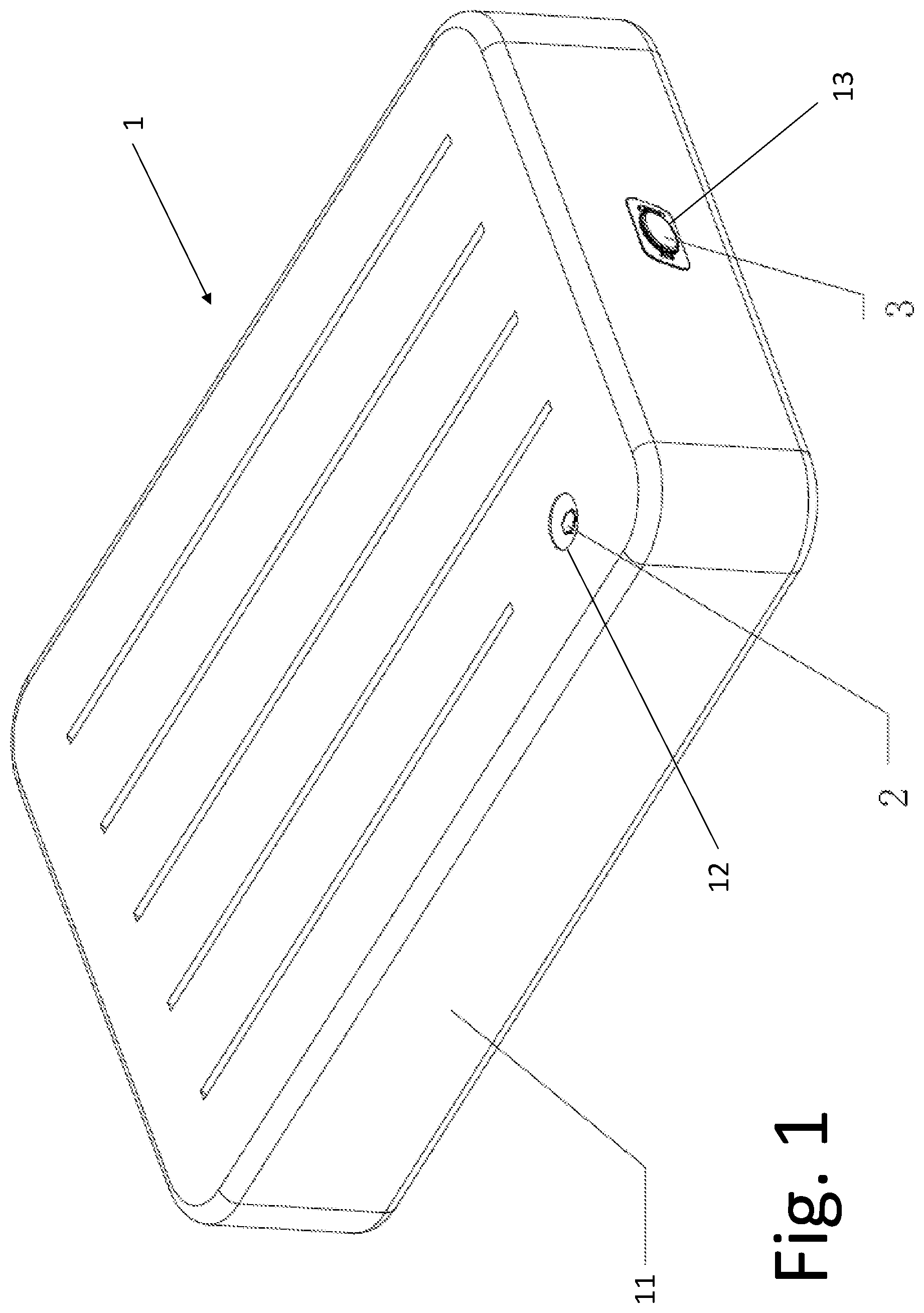
The present application claims priority to Chinese Application No. CN201920947874.6 filed Jun. 21, 2019 and entitled INFLATABLE BED WITH TWO TYPES OF AIR PUMPS and Chinese Application No. CN201921084697.X filed Jul. 11, 2019 and entitled AN INTERNAL AND EXTERNAL AIR PUMP ASSEMBLY, the entire disclosures of which are hereby incorporated by reference herein. The present disclosure relates to an inflatable product, in particular to an inflatable product including an electric air pump and an auxiliary air supply. Inflatable products, such as inflatable beds, inflatable rubber boats, etc., may be inflated by an electric air pump (either internal or external) or by a manual/foot-operated air pump (either internal or external). Many common inflatable products are inflated solely by electric air pump with sufficient power to ensure adequate inflation. For example, many inflatable products require nominal inflation pressures above 180 mm WC. However, most electric air pumps operate at very poor efficiencies at this pressure. To overcome this deficiency, more power and design must be put into pumps. This, in turn greatly increases the cost of manufacturing and the power requirement for these electric pumps is high, particularly when using batteries to power the pump. On the other hand, if an inflatable product is large, using a manual air pump is very time-consuming and labor-intensive. This puts limitations on which consumers can even operate certain products. What is needed is an improvement over the foregoing. The present disclosure provides an inflatable product which can be inflated to a low pressure by a lower-power but high-volume electric pump, then “firmed” or fully inflated by an auxiliary pump. The auxiliary pump may be manually powered, such that the overall cost and complexity of the electric and auxiliary pumps are still lower than a high-power electric pump. The low power high volume electric pump can be easily powered by small batteries that will also provide an increased number of inflations compared to traditional high-power pumps for a given battery capacity. Using small batteries allows the pump to be very compact in size. The auxiliary pump may work through an auxiliary air chamber within the primary air chamber and fluidly connected thereto by a check valve. The electric pump may be reversible to provide for both inflation and deflation. In one form thereof, the present disclosure provides an inflatable product including a product body defining a primary inflatable chamber and having an electric pump aperture and an auxiliary air supply aperture formed therein; an electric air pump mounted on the product body through the electric pump aperture; and an auxiliary air supply mounted to the product body at the auxiliary air supply aperture, the auxiliary air supply defining an auxiliary air supply chamber defining an internal air volume nominally separate from, but contained within, the primary inflatable chamber of the product body. In another form thereof, the present disclosure provides a method of inflating an inflatable product, including: using an electric air pump to inflate the inflatable product from a deflated state to a partially inflated state; and using an auxiliary air supply to supplement the air pressure developed by use of the electric air pump, to thereby inflate the inflatable product from the partially inflated state to a fully inflated state. The “fully inflated” state may be defined by a user's preference. The above-mentioned and other features of the disclosure, and the manner of attaining them, will become more apparent and will be better understood by reference to the following description of embodiments of the disclosure taken in conjunction with the accompanying drawings, wherein: Corresponding reference characters indicate corresponding parts throughout the several views. The exemplifications set out herein illustrate embodiments of the disclosure and such exemplifications are not to be construed as limiting the scope of the disclosure in any manner. Turning now to In the illustrated embodiment of In one exemplary operation of inflatable product 1, electric air pump 3 is used to inflate inflatable product 1 from a deflated state to a partially inflated state, then electric air pump 3 is turned off. Auxiliary air supply 2 is then used to supplement the air pressure developed by use of electric air pump 3, taking the inflated product 1 from the partially inflated state to the fully inflated state. In the fully deflated state, the volume of air within the chamber is zero or very close to zero, e.g., less than 5% of the nominal volumetric capacity of mattress 1. In the fully inflated state, the volume of air is sufficient to achieve a “firm” mattress 1, such as a pressure between 160-200 mm water column. For example, if it is necessary to raise the air pressure in inflatable product 1 from 0 mm to 200 mm water column, electric air pump 3 may be used to initially inflate the interior chamber of product body 11 from 0 mm to a relatively low intermediate pressure, such as by delivering sufficient air to raise the internal pressure to between 15-25 mm water column (nominally 20 mm water column). This relatively low pressure can be delivered by a low-power, low-cost pump compared to electric pumps capable of delivering a full pressure of 160-200 mm water column. Although the air pressure capable of being generated by electric air pump 3 is relatively represents only 10% of the nominal target pressure, it represents a large percentage of the volume of air needed to fully inflate product 1, such as between 95.0% and 99.5% of the total air volume needed to inflate mattress 1 from a fully deflated state to a fully inflated state. The percentage of the capacity of inflatable product 1 that is achievable for a given intermediate pressure capability of pump 3 may depend on the elasticity of the inflatable product. Relatively rigid, inelastic materials (e.g., reinforced materials used for inflatable spas) can be inflated from 20 mm water column to 200 mm water column with minimal volumetric expansion, such that only a small percentage of the total capacity is needed to raise the pressure. Conversely, relatively soft, elastic materials (e.g., materials used for inflatable mattresses such as mattress 1) may expand as the internal pressure increases, such that a relatively larger percentage of total capacity is needed to raise the pressure. In order to achieve the fully inflated volume and pressure, the remaining 0.5-5.0% of the air volume of inflatable product 1 can be delivered by auxiliary air supply 2. At this point, most of the volume of air needed for full inflation is already contained within the inflatable chamber. For the illustrated embodiment of auxiliary air supply 2, discussed in more detail below, a small number of manual compressions may be sufficient to provide the final volume pumped air and thereby complete inflation to a fully inflated state. For purposes of the present disclosure, a “fully inflated” state of inflatable product 1 may correspond to a firm inflation pressure of 200 mm water column, it being understood that the final internal pressure may vary according to user preference. For auxiliary air supply 2, between 4-10 compressions may be required to increase the internal pressure from 20 mm water column to 200 mm water column. By contrast, if electric air pump 3 were not used and the full 200 mm water column were provided solely by auxiliary air supply 2, between 200 and 2000 manual compressions would be required. Thus, in the present method in which the electric air pump 3 is first utilized to provide a large volume of air, and auxiliary air supply 2 is only used after electric air pump 3 has achieve a low pressure within the interior chamber, a low-power pump can be mated with minimal manual pumping to provide complete inflation. As an alternative to this “staggered” use of the two pump mechanisms, electric air pump 3 and auxiliary air supply 2 can also work simultaneously. Turning now to in In the exemplary embodiment shown in As shown in Auxiliary air supply chamber 21 includes check valve 24, shown in During operation, electric air pump 3 is used to inflate inflatable product 1 from a deflated state to a partially inflated state, then electric air pump 3 is turned off. The user then opens valve cover 23 and removes seal 222 thus allowing the chamber 21 to expand and fill with air. The user then covers the air inlet 221 with his or her hand or foot and presses downward on the air supply 2 to force air through check valve 24 causing additional inflation of the primary chamber of inflatable product 1. The user continues compressions of air supply 2 until the desired internal air pressure is achieved. When the user removes his or her hand or foot from air inlet 221, seal 222 may close to prevent any escape of air from auxiliary supply chamber 21. In this way, the auxiliary inflation function of auxiliary air supply 2 is realized. Turning again to Referring now to Opposite clip retainer 334 and shown in Referring still to Opposite of clip 333 and shown in Valve cover 312 also includes air inlet 3121 which is an aperture in valve cover 312 that provides communication between the external environment and the inner chamber of inflatable product 1. Fitting within air inlet 3121 is cap 3122 which is designed to provide an air-tight seal over air inlet 3121. Inlet 3121 leads to check valve 314. Check valve 314 includes a stem 335 which extends up from check valve 314 and into valve 31. At a bottom end of stem 335 is groove 336. Groove 336 is a thin portion of stem 335 terminating on one end by check valve 314 and at the other end with a radial extension of stem 335. As shown in During inflation with a separate manual pump (not shown), when air is being pumped through inlet 3121, check valve 314 is urged open by the air flow and pressure, which allows air to be pumped into the internal chamber of inflatable body 11 ( Although a rotatable connection is illustrated, valve cover 312 and valve base 311 can also be provided as two separate and independent parts. When valve base 311 needs to be closed, valve cover 312 is attached to valve base 311 and when valve base 311 needs to be opened, valve cover 312 is removed from valve base 311. As mentioned above and as shown in Also shown in Referring still to Motor 323 also includes output shaft 344 which is configured to be rotatably driven by motor 323. Coupled to an end of output shaft 344, and shown in Also shown in Lastly, as shown in During installation, housing 321 is first inserted into mounting groove 313 by aligning peg 349 with first portion 3131 by sliding peg 349 into first portion 3131. Then pump 32 is axially advanced by sliding housing 321 through aperture 351, guided by the interaction between peg 349 and first portion 3131 of groove 313, until peg 349 of housing 321 enters the connection between first portion 3131 and second portion 3132. At this time, pump 32 is rotated to make peg 349 enter second portion 3132. Finally, pump 32 is rotated further such that peg 349 is slid across the length of second portion 3132 and over locking protrusion 3133. At this point, peg 349 is locked into place within mounting groove 313. When electric air pump 3 is to be disassembled, or a change in configuration is needed, it is only necessary to rotate pump 32 in the reverse direction to unlock peg 349 from locking protrusion 3133, and continue to rotate and lift pump 32 from mounting groove 313. Because pump 32 and valve 31 are detachably connected together, the user can choose to install pump 32 on valve 31 to form a built-in electric air pump 3, or remove pump 32 from valve 31 to form an external electric air pump 3. Users can switch between these two modes at will according to their needs and usage scenarios. When pump 32 is installed in the forward direction, the air outlet extends into the internal chamber of product body 11 as shown in Turning to By contrast, As discussed above, in order to control pump 32, pump 32 includes switch 324, and valve cover 312 includes a trigger member that cooperates with switch 324. When valve cover 312 is in the closed configuration, the trigger member contacts switch 324 to turn off switch 324, and pump 32 automatically stops working. The trigger element may be a pressure block positioned to turn off switch 324 by using a squeezing force between the pressure block and switch 324. When valve cover 312 is in the opened configuration, the pressing force disappears, and switch 324 is turned on again. Therefore, when pump 32 is installed in valve 31, as long as valve cover 312 is in the opened configuration, pump 32 automatically starts to inflate. When the user closes valve cover 312, pump 32 will automatically stop inflation. While this disclosure has been described as having exemplary designs, the present disclosure can be further modified within the spirit and scope of this disclosure. This application is therefore intended to cover any variations, uses, or adaptations of the disclosure using its general principles. Further, this application is intended to cover such departures from the present disclosure as come within known or customary practice in the art to which this disclosure pertains and which fall within the limits of the appended claims. An inflatable product can be inflated to a low pressure by a lower-power but high-volume electric pump, then “firmed” or fully inflated by an auxiliary pump. The auxiliary pump may be manually powered, such that the overall cost and complexity of the electric and auxiliary pumps are still lower than a high-power electric pump. The low power high volume electric pump can be easily powered by small batteries that will also provide an increased number of inflations compared to traditional high-power pumps for a given battery capacity. Using small batteries allows the pump to be very compact in size. The auxiliary pump may work through an auxiliary air chamber within the primary air chamber and fluidly connected thereto by a check valve. The electric pump may be reversible to provide for both inflation and deflation. 1. An inflatable product comprising:
a product body defining a primary inflatable chamber and having an electric pump aperture and an auxiliary air supply aperture formed therein; an electric air pump mounted on the product body through the electric pump aperture; and an auxiliary air supply mounted to the product body at the auxiliary air supply aperture, the auxiliary air supply defining an auxiliary air supply chamber defining an internal air volume nominally separate from, but contained within, the primary inflatable chamber of the product body. 2. The inflatable product of the electric air pump is configured to inflate the inflatable product from a deflated state to a partially inflated state in which the inflatable product body contains between 95.0% and 99.5% of the nominal air capacity, and the auxiliary air supply is configured to inflate the inflatable product from the partially inflated state to a fully inflated state by providing the final 0.5-5.0% of the of the nominal air capacity. 3. The inflatable product of the electric air pump is capable of delivering a maximum pressure between 15-25 water column, whereby the electric air pump is a low-power design, and the auxiliary air supply is configured to deliver a pressure between 160-200 mm water column. 4. The inflatable product of an auxiliary air supply wall sealingly connected to an interior surface of the inflatable product about the auxiliary air supply aperture to define the auxiliary air supply chamber; a valve coupled to the auxiliary air supply aperture, the valve having an air inlet configured to selectively receive or discharge air therethrough; and a check valve passing through the auxiliary air supply wall and configured to provide one-way fluid communication from auxiliary supply chamber to the primary inflatable chamber. 5. The inflatable product of a seal disposed about the auxiliary air supply aperture and configured to sealingly receive an external pump; and a valve cover removably sealingly engaged with the air inlet and the seal. 6. The inflatable product of a valve including a valve base having an aperture therethrough and a valve cover configured to open or close the aperture; and a pump detachably coupled to the valve in an inflation configuration in which the pump is operable to transmit air into the interior of the inflatable product body, and a deflation configuration in which the pump is operable to transmit air out of the interior of the inflatable product body. 7. The inflatable product of 8. The inflatable product of 9. The inflatable product of a switch; a power source operably coupled to the switch; a motor operably coupled to the power source via the switch; and a housing which contains at least the power source and the motor. 10. The inflatable product of the housing includes a peg extending radially outward therefrom; and the valve base of the valve includes a mounting groove sized to receive the peg and configured to selectively couple the electric air pump in the inflation configuration and the deflation configuration. 11. The inflatable product of the mounting groove includes a first portion configured to guide the housing through the aperture along an axial direction, and the mounting groove includes a second portion configured to guide the housing through a rotation within the aperture. 12. The inflatable product of 13. The inflatable product of 14. The inflatable product of the electric pump aperture is formed in the sidewall of the mattress, and the auxiliary air supply aperture is formed in one of the top and bottom sheets. 15. A method of inflating an inflatable product, comprising:
using an electric air pump to inflate the inflatable product from a deflated state to a partially inflated state; and using an auxiliary air supply to supplement the air pressure developed by use of the electric air pump, to thereby inflate the inflatable product from the partially inflated state to a fully inflated state. 16. The method of the step of using an electric air pump comprises adding air to the inflatable product equal to between 95.0% and 99.5% of a nominal air capacity thereof; and the step of using an auxiliary air supply comprises adding air to the inflatable product equal to the final 0.5-5.0% of the of the nominal air capacity.CROSS-REFERENCE TO RELATED APPLICATIONS
BACKGROUND
1. Technical Field
2. Description of the Related Art
SUMMARY
BRIEF DESCRIPTION OF THE DRAWINGS
DETAILED DESCRIPTION