CRAWLED VEHICLE FOR THE PREPARATION OF SKI PISTES
This application is a national stage application of PCT/IB2019/051676, filed on Mar. 1, 2019, which claims the benefit of and priority to Italian Patent Application No. 102018000003244, filed on Mar. 2, 2018, the entire contents of which are each incorporated by reference herein. The present disclosure relates to a crawled vehicle for the preparation of ski pistes. In particular, the present disclosure relates to a crawled vehicle comprising a frame; two wheel assemblies arranged on opposite sides of the frame; two crawls arranged around the respective wheel assemblies; and at least one supporting device for each wheel assembly, which is coupled to at least two wheels of the wheel assembly and is connected to the frame so as to couple said at least two wheels of the wheel assembly to the frame. Certain drawbacks of certain of the prior art lies in the fact that said crawled vehicle has undesired vibrations. An object of the present disclosure is to provide a crawled vehicle which is capable of reducing certain of the drawbacks of certain of the prior art. According to the present disclosure, there is provided a crawled vehicle for the preparation of ski pistes; the crawled vehicle comprising:
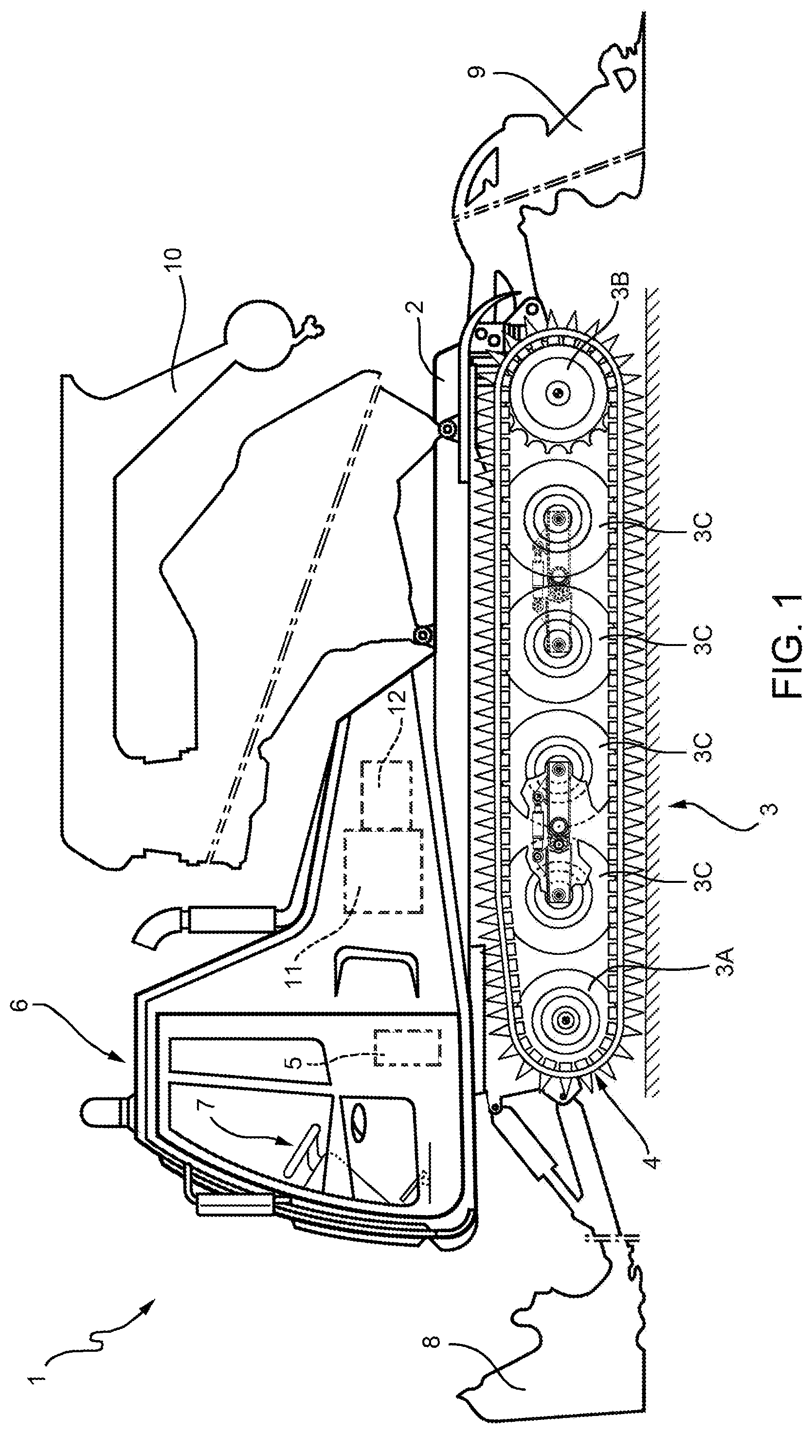
It should be appreciated that in accordance with the present disclosure, the two wheels of the wheel assembly are connected to one another through the supporting device, so as to have at least one degree of freedom of movement relative to one another, which reduces the vibrations transmitted to the frame. According to certain embodiments, the first supporting element and the second supporting element are connected to one another through an elastic structure, in particular a leaf spring, a fibreglass structure or a carbon structure. According to certain embodiments, the supporting device comprises an elastic structure, in particular a leaf spring, a fibreglass structure or a carbon structure; the first supporting element and the second supporting element, in particular the first supporting element and the second supporting element are defined by respective portions or by respective ends of the elastic structure, in particular by respective portions or ends of the leaf spring or fibreglass structure or carbon structure. According to certain embodiments, the supporting device comprises a further articulated joint to couple the first supporting element to the second supporting element in an articulated manner, said further articulated joint is, in certain embodiments, a hinge. According to another embodiment, the first and the second supporting element are connected to one another through a shock absorber, in particular in a second point different from the first point. According to different embodiments, the shock absorber has a variable stiffness and/or a variable geometry. According to different embodiments, the shock absorber is mechanical and/or hydraulic and/or electromagnetic and/or an air suspension or any combination thereof. According to another embodiment, the supporting device comprises a connection articulated joint coupled to the frame in order to couple the supporting device to the frame in an articulated manner; the articulated connection joint is, in certain embodiments, a hinge. According to different embodiments, the connection articulated joint is partly housed on the first and/or on the second supporting element. According to another embodiment, said at least two wheels of the wheel assembly are supporting wheel in particular free rotating wheel. According to another embodiment, the wheel assembly comprises a driving wheel, such as a rear wheel. According to another embodiment, the wheel assembly comprises a crawl regulating wheel, such as a front wheel, having a mobile position with respect to the frame so as to stretch the crawl. According to another embodiment, said at least two wheels are middle wheels between the crawl regulating wheel and the driving wheel and, in certain embodiments, are free rotating wheels. According to another embodiment, the supporting device is connected to the frame through a shock absorber assembly. According to different embodiments, the shock absorber assembly has a variable stiffness and/or a variable geometry. According to another embodiment, the shock absorber assembly comprises a double-acting hydraulic cylinder. According to different embodiments, the shock absorber assembly is mechanical and/or hydraulic and/or electromagnetic and/or an air suspension or any combination thereof. According to another embodiment, each wheel assembly comprises a crawl regulating wheel, such as a front wheel, a driving wheel, such as a rear wheel, two pairs of supporting wheels and two supporting devices, each coupled to one respective pair of supporting wheels. Other features and advantages of the present disclosure will be best understood upon perusal of the following description of a non-limiting embodiment thereof, with reference to the accompanying drawing, wherein: With reference to With reference to With reference to Each wheel assembly 3 comprises a front wheel 3 With reference to With reference to The configurations of the crawls 4 depend on the configurations of the respective wheel assemblies 3. In particular, each wheel assembly 3 can be adjusted between different configurations, so as to adjust a crawl portion in contact with the snow surface M. The central wheels 3 For each supporting device 15, the crawled vehicle 1 comprises a shock absorber assembly 160 with a variable configuration and a variable stiffness to connect the respective two central wheels 3 In certain non-limiting examples of the present disclosure discussed herein, the crawled vehicle 1 comprises a supporting device 15 for each pair of central wheels 3 Furthermore, each supporting device 15 couples the respective two central wheels 3 With reference to Furthermore, the first and the second supporting element 16 and 17 are connected to one another through a shock absorber 20, in particular in points 21 that are different from the point 19. In more detail, the supporting device 15 comprises the shock absorber 20, which is connected to the first and to the second element by articulated joints 22 placed in the points 21, in particular two articulated joints 22 in the two points 21. In certain embodiments, the articulated joints 22 are hinges. In certain embodiments, the shock absorber 20 has a variable stiffness. In another embodiment, the shock absorber 20 has a variable geometry. In another embodiment, the shock absorber 20 has a variable stiffness and a variable geometry. In different embodiments, the shock absorber 20 is mechanical and/or hydraulic and/or electromagnetic and/or an air suspension or any combination thereof. In more detail, the supporting device 15 comprises a connection articulated joint 123, which is partly housed on the first supporting element 16 and is coupled to the frame 2 so as to couple the supporting device 15 to the frame 2 in an articulated manner. In certain embodiments, the articulated joint 123 is a hinge. The central wheels 3 With reference to The hydraulic cylinder 23 has a first end fixed to the frame 2 so as to rotate around an axis A5, which is parallel to the axes A1. In this way, by changing the length of the hydraulic cylinder 23, it is possible to change the distance of the supporting device 15 from the frame 2 or, even better, the distance of the axis A2 from the frame 2, because the supporting device 15 can freely oscillate around the axis A2 and, hence, change the position of the respective central wheels 3 relative to the frame 2. The control assembly 5 comprises a control unit 13 and the user interface 7 and has the function of acquiring a signal indicating an operating state of the crawled vehicle 1 as a function of at least one operating parameter of the crawled vehicle and, in certain embodiments, of a plurality of operating parameters, as well as the function of adjusting the configurations of the wheel assemblies 3 as a function of the signal indicating the operating state, in particular the function of adjusting the configuration and/or the stiffness of the shock absorber assemblies 160. In certain non-limiting embodiments of the present disclosure, the control units 13, through the signal indicating the operating state, controls the shock absorbers 20 one-by-one or jointly. In particular, through a manual mode, the driver controls both the position and the stiffness of the shock absorber assembly 160 and/or of each shock absorber or of all shock absorbers 20 through the support of the displaying on the user interface 7. In an alternative embodiment of the present disclosure and with reference to Furthermore, the supporting device 115, similarly to the supporting device 15, comprises a connection articulated joint 223, which is connected to the elastic structure 225 by a connection element 226. The connection articulated joint 223 is coupled to the frame 2 so as to couple the supporting device 115 to the frame 2 in an articulated manner. In certain embodiments, the articulated joint 223 is a hinge. In this embodiment, the elastic structure 225 enables the central wheels 3 It should be appreciated that the present disclosure also covers embodiments that are not described in the detailed description above as well as equivalent embodiments that are part of the scope of protection set forth in the appended claims. Accordingly, various changes and modifications to the presently disclosed embodiments will be apparent to those skilled in the art. Crawled vehicle for the preparation of ski pistes; the crawled vehicle comprising a frame; two wheels assemblies displaced at opposite side with respect to the frame; two crawls, each of them wounded respectively around to one of the two wheels assemblies; and at least one supporting device, for each wheels assemblies, coupled to at least two wheels of the wheel assembly and connected in an articulated jointed manner to the frame for coupling the at least two wheels of the wheels assembly to the frame; wherein the supporting device has a first supporting element, which supports one of the at least two wheels of the wheels assembly; and a second supporting element, which supports another of the two wheels of the wheels assembly; and wherein the first supporting element and the second supporting element are connected to one another through a first articulated joint in a first point. 1-15. (canceled) 16. A crawled vehicle comprising:
a frame; a first wheel assembly at a first side of the frame; a first crawl wound around the first wheel assembly; a second wheel assembly at a second, opposite side of the frame; a second crawl wound around the second wheel assembly; and at least one supporting device for each wheel assembly, wherein:
for each wheel assembly, the at least one supporting device is coupled to at least two wheels of that wheel assembly and articulately jointedly connected to the frame to couple the at least two wheels of that wheel assembly to the frame, and for each wheel assembly, the at least one supporting device has a first supporting element which supports one of the at least two wheels of that wheel assembly and a second supporting element which supports another one of the at least two wheels of that wheel assembly such that the first supporting element and the second supporting element are one of: elastically flexibly connected and connected through a first articulated hinged joint at a first point. 17. The crawled vehicle of 18. The crawled vehicle of the at least one supporting device for that wheel assembly comprises an elastic structure comprising one of: a leaf spring, a fiberglass structure, and a carbon structure, and the first supporting element and the second supporting element are defined by one of: a portion of the one of the leaf spring, a portion of the fiberglass structure, a portion of the carbon structure, an end of the leaf spring, an end of the fiberglass structure, and an end of the carbon structure. 19. The crawled vehicle of 20. The crawled vehicle of 21. The crawled vehicle of 22. The crawled vehicle of 23. The crawled vehicle of 24. The crawled vehicle of 25. The crawled vehicle of 26. The crawled vehicle of 27. The crawled vehicle of 28. The crawled vehicle of 29. The crawled vehicle of 30. The crawled vehicle of 31. The crawled vehicle of 32. A crawled vehicle wheel assembly comprising:
at least two wheels; and at least one supporting device coupled to the at least two wheels and configured to be articulately jointedly connected to a frame of a crawled vehicle to couple the at least two wheels to the frame, wherein the at least one supporting device comprises:
a first supporting element which supports one of the at least two wheels, and a second supporting element which supports another one of the at least two wheels such that the first supporting element and the second supporting element are one of: elastically flexibly connected and connected through a first articulated hinged joint at a first point.PRIORITY CLAIM
TECHNICAL FIELD
BACKGROUND
SUMMARY
BRIEF DESCRIPTION OF THE DRAWINGS
DETAILED DESCRIPTION