CLOTHES CARE APPARATUS AND CONTROL METHOD THEREOF
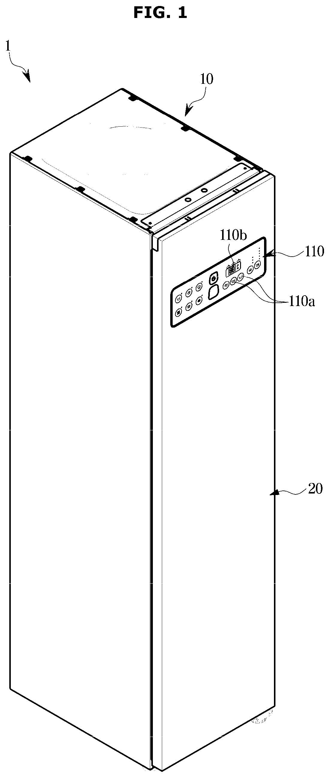
This application is based on and claims priority under 35 U.S.C. § 119 to Korean Patent Application No. 10-2019-0086534 filed on Jul. 17, 2019 in the Korean Intellectual Property Office, the disclosure of which is incorporated by reference herein in its entirety. The disclosure relates to a clothes care apparatus for smoothing out the wrinkles of clothes and removing dust attached to the clothes or smell of the clothes. A clothes care apparatus is equipment for caring clothes, such as drying wet clothes, removing dust attached to clothes or smell permeated clothes, and smoothing out the wrinkles of clothes. The clothes care apparatus performs a function of supplying hot air to clothes to dry the clothes and a function of spraying steam to clothes to remove the wrinkles of the clothes and remove smell permeated the clothes. The hot air may be supplied by a blower, and the steam may be supplied by a steam generator. Meanwhile, a typical clothes care apparatus senses the temperature of inside air of the chamber to determine a load of clothes and control a dry time, while performing a dry process of drying the clothes after spraying steam to the clothes. However, the typical clothes care apparatus does not determine a load of clothes during a steam process. Therefore, it is an aspect of the disclosure to provide a clothes care apparatus capable of determining, during a steam process of spraying steam to clothes, an amount of humidity change inside a chamber at an initial stage of the steam process, and adjusting a steam spray time based on the amount of humidity change, thereby preventing drying errors while preventing a dry time from increasing, and a method of controlling the clothes care apparatus. It is another aspect of the disclosure to provide a clothes care apparatus capable of determining, during a steam process, a water load of clothes based on an amount of humidity change inside a chamber and adjusting a steam spray time based on the water load of the clothes, and a method of controlling the clothes care apparatus. Additional aspects of the disclosure will be set forth in part in the description which follows and, in part, will be obvious from the description, or may be learned by practice of the disclosure. In accordance with an aspect of the disclosure, a clothes care apparatus includes: a chamber accommodating clothes; a humidity sensor positioned inside the chamber; a steam generator configured to supply steam to inside of the chamber; and a controller configured to determine an amount of humidity change inside the chamber based on an output value from the humidity sensor during a steam process, and control the steam generator to supply the steam based on the amount of humidity change. The controller may be further configured to adjust a steam spray time based on the amount of humidity change, and control the steam generator to supply the steam for the steam spray time. The controller may be further configured to determine the steam spray time as a default steam spray time or reduce the steam spray time to a value that is smaller than the default steam spray time, based on the amount of humidity change. The controller may be further configured to more reduce the steam spray time at the greater amount of humidity change. The controller may be further configured to adjust a degree of reduction of the steam spray time based on a kind of clothes. The clothes care apparatus according to an embodiment of the disclosure may further include a fan configured to cause inside air of the chamber to flow, wherein the controller may be further configured to operate the fan for a preset time and determine the amount of humidity change, at an initial stage of the steam process. The controller may be further configured to operate at least one of an upper fan positioned above the chamber and configured to move air in a down direction of the chamber or a lower fan positioned below the chamber and configured to move air in an up direction of the chamber. The amount of humidity change may be an amount of humidity increase inside the chamber after a preset time elapses at an initial stage of the steam process. The clothes care apparatus according to an embodiment of the disclosure may further include a display, wherein the controller may be further configured to control the display to display the steam spray time. In accordance with another aspect of the disclosure, a method of controlling a clothes care apparatus includes: measuring humidity inside a chamber during a steam process by using a humidity sensor; determining an amount of humidity change inside the chamber based on an output value from the humidity sensor; and controlling the steam generator to supply steam to inside of the chamber based on the amount of humidity change. The controlling of the steam generator may include: adjusting a steam spray time based on the amount of humidity change; and controlling the steam generator to supply the steam for the steam spray time. The adjusting of the steam spray time may include determining the steam spray time as a default steam spray time or reducing the steam spray time to a value that is smaller than the default steam spray time, based on the amount of humidity change. The adjusting of the steam spray time may include more reducing the steam spray time at the greater amount of humidity change. The adjusting of the steam spray time may include adjusting a degree of reduction of the steam spray time based on a kind of clothes. The method according to an embodiment of the disclosure may further include operating a fan configured to cause inside air of the chamber to flow for a preset time, at an initial stage of the steam process. The operating of the fan may include operating at least one of an upper fan positioned above the chamber and configured to move air in a down direction of the chamber or a lower fan positioned below the chamber and configured to move air in an up direction of the chamber. The amount of humidity change may be an amount of humidity increase inside the chamber after a preset time elapses at an initial stage of the steam process. The method according to an embodiment of the disclosure may further include controlling a display to display the steam spray time. In accordance with another aspect of the disclosure, a clothes care apparatus includes: a chamber accommodating clothes; a humidity sensor positioned inside the chamber; a steam generator configured to supply steam to inside of the chamber; and a controller configured to determine a water load of the clothes based on an output value from the humidity sensor during a steam process, and control the steam generator to supply the steam based on the water load of the clothes. The controller may be further configured to determine the water load of the clothes based on an amount of humidity change inside the chamber at an initial stage of the steam process, adjust a steam spray time based on the water load of the clothes, and control the steam generator to supply the steam for the steam spray time. Before undertaking the DETAILED DESCRIPTION below, it may be advantageous to set forth definitions of certain words and phrases used throughout this patent document: the terms “include” and “comprise,” as well as derivatives thereof, mean inclusion without limitation; the term “or,” is inclusive, meaning and/or; the phrases “associated with” and “associated therewith,” as well as derivatives thereof, may mean to include, be included within, interconnect with, contain, be contained within, connect to or with, couple to or with, be communicable with, cooperate with, interleave, juxtapose, be proximate to, be bound to or with, have, have a property of, or the like; and the term “controller” means any device, system or part thereof that controls at least one operation, such a device may be implemented in hardware, firmware or software, or some combination of at least two of the same. It should be noted that the functionality associated with any particular controller may be centralized or distributed, whether locally or remotely. Moreover, various functions described below can be implemented or supported by one or more computer programs, each of which is formed from computer readable program code and embodied in a computer readable medium. The terms “application” and “program” refer to one or more computer programs, software components, sets of instructions, procedures, functions, objects, classes, instances, related data, or a portion thereof adapted for implementation in a suitable computer readable program code. The phrase “computer readable program code” includes any type of computer code, including source code, object code, and executable code. The phrase “computer readable medium” includes any type of medium capable of being accessed by a computer, such as read only memory (ROM), random access memory (RAM), a hard disk drive, a compact disc (CD), a digital video disc (DVD), or any other type of memory. A “non-transitory” computer readable medium excludes wired, wireless, optical, or other communication links that transport transitory electrical or other signals. A non-transitory computer readable medium includes media where data can be permanently stored and media where data can be stored and later overwritten, such as a rewritable optical disc or an erasable memory device. Definitions for certain words and phrases are provided throughout this patent document, those of ordinary skill in the art should understand that in many, if not most instances, such definitions apply to prior, as well as future uses of such defined words and phrases. For a more complete understanding of the present disclosure and its advantages, reference is now made to the following description taken in conjunction with the accompanying drawings, in which like reference numerals represent like parts: Like numbers refer to like elements throughout this specification. This specification does not describe all components of the embodiments, and general information in the technical field to which the disclosure belongs or overlapping information between the embodiments will not be described. The terms “portion”, “device”, “block”, “member”, and “module”, as used herein, may be implemented as software or hardware. In addition, the terms “portion”, “device”, “block”, “member”, and “module” used herein refer to a unit for processing at least one function or operation. Also, the terms “portion”, “device”, “block”, “member”, and “module” may mean at least one process that is processed by at least one software or processor stored in at least one hardware, circuit, or memory. According to some embodiments, the “portion”, “device”, “block”, “member”, and “module” may include at least one component. Throughout the specification, it will be understood that when a certain portion is referred to as being “connected” to another portion, it can be directly or indirectly connected to the other portion. When a portion is indirectly connected to another portion, it may be connected to the other portion through a wireless communication network. Also, it will be understood that when the terms “includes,” “comprises,” “including,” and/or “comprising,” when used in this specification, specify the presence of a stated component, but do not preclude the presence or addition of one or more other components. It will be understood that, although the terms “first”, “second”, etc., may be used herein to describe various elements, these elements should not be limited by these terms. The above terms are used only to distinguish one component from another. It is to be understood that the singular forms “a,” “an,” and “the” include plural referents unless the context clearly dictates otherwise. Reference numerals used in operations are provided for convenience of description, without describing the order of the operations, and the operations can be executed in a different order from the stated order unless a specific order is definitely specified in the context. Throughout the disclosure, the expression “at least one of a, b or c” indicates only a, only b, only c, both a and b, both a and c, both b and c, all of a, b, and c, or variations thereof. Hereinafter, the embodiments of the disclosure will be described with reference to the accompanying drawings. Referring to The door 20 may include a user interface 110 to enable a user to input commands related to operations of the clothes care apparatus 1. The user interface 110 may be positioned on the front side of the door 20. The user interface 110 may include an inputter 110 Referring to The main body 10 may include an outer frame 11, an inner frame 12 installed inside the outer frame 11, and upper ducts 13 and 14 (also, referred to as a first upper duct 13 and a second upper duct 14) positioned between the outer frame 11 and the inner frame 12 to guide air to circulate. The outer frame 11 may be in a shape of a rectangular parallelepiped of which the front side opens to form an inside space 11 The inner frame 12 may be positioned in the inside space 11 A water supply container 58 and a drain container 59 may be removably installed in the lower cover 12 Referring to The machine room 11 Also, the steam generator 180 may be installed in the machine room 11 Steam generated by the steam heater 181 may move to the steam spray 183 through the steam supply pipe 182, and be supplied to the chamber 12 Meanwhile, the main body 10 of the clothes care apparatus 1 may include a fan 200. The fan 200 may include the upper fan 210 and a lower fan 220. The upper fan 210 is also referred to as a first fan 210, and the lower fan 220 is also referred to as a second fan 220. The upper fan 210 may be positioned above the chamber 12 A shaft of the upper motor 211 may protrude at its both sides, and the upper blade 212 may be coupled to each of both ends of the shaft. Through the structure, the upper motor 211 may rotate a pair of upper blades 212. The upper fan 210 may be a centrifugal fan for inhaling air in an extension direction of the shaft and discharging the air outward in a radial direction, although not limited thereto. Also, the pair of upper blades 212 may be provided, although not limited thereto. According to a design, a plurality of upper blades 212 may be provided. At both sides of the blade case 213, an intake opening may be formed, and at a front side of the blade case 213, a discharge opening may be formed so that the blade case 213 guides air inhaled at its both sides to the front side. The lower fan 220 may inhale air to the inside of the machine room 11 The lower fan 220 may be a centrifugal fan for inhaling air in an extension direction of the shaft and discharging the air outward in a radial direction, although not limited thereto. Also, a single lower blade 221 may be provided, although not limited thereto. According to a design, a plurality of lower blades 221 may be provided. Air flowing by the lower blade 221 may be dried by the lower heat exchanger 60. Therefore, clothes placed inside the chamber 12 Referring to When the upper fan 210 operates, inside air of the chamber 12 A lower end of the first upper duct 13 may be connected to a lower area of the rear plate of the chamber 12 The first discharge opening 12 Meanwhile, an upper heater 44 may be positioned inside the second upper duct 14. The upper heater 44 may heat air moving by the upper fan 210. Accordingly, hot air may flow to the inside of the chamber 12 In an upper plate of the machine room 11 Inside air of the chamber 12 Inside the second lower duct 56, the evaporator 63 and the condenser 62 of the lower heat exchanger 60 may be positioned. The evaporator 63 may absorb heat from inside air of the second lower duct 56. Water included in the air may be condensed when the air passes through the evaporator 63, and the condensed water may be stored in the drain container 59 through a preset path. The condenser 62 may be positioned downstream from the evaporator 63 on a flow path of air. The air of which the humidity is lowered by passing through the evaporator 63 may be heated when passing through the condenser 62. By passing through the evaporator 63 and the condenser 62, temperature of the air may increase and humidity of the air may be lowered. As a result, high-temperature dry air may enter the chamber 12 A conventional clothes care apparatus sprays, when performing a steam process, steam to the inside of a chamber, without determining a water load of clothes. In other words, the typical clothes care apparatus performs a steam process without distinguishing a case of accommodating dry clothes inside the chamber 12 Because a process of heating water to generate steam and a process of drying clothes consume a lot of power, an increase of a dry time lowers energy efficiency. Also, because spraying a large amount of steam onto wet clothes is unnecessary and deteriorates energy efficiency, it may be needed to optimize the steam process according to a water load of clothes. Hereinafter, operations of the clothes care apparatus 1 for optimizing a steam process according to a water load of clothes will be described. Referring to The controller 300 may include a memory 320 for memorizing and/or storing programs, instructions, and data for controlling operations of the clothes care apparatus 1, and a processor 310 for generating control signals for controlling operations of the clothes care apparatus 1 based on the programs, instructions, and data memorized and/or stored in the memory 320. The processor 310 and the memory 320 may be implemented as separate chips, or integrated into a single chip. Also, the controller 300 may include a plurality of processors and a plurality of memories. The processor 310 may include a logic circuit and an arithmetic circuit, as hardware. The processor 310 may process data according to a program and/or instruction provided from the memory 320, and generate a control signal according to the result of the processing. For example, when a user controls the user interface 110 to input a command of selecting a care course, the clothes care apparatus 1 may perform a clothes care operation corresponding to the selected care course. The memory 320 may include a volatile memory, such as Static Random Access Memory (S-RAM) and Dynamic Random Access Memory (D-RAM), for temporarily storing data, and a non-volatile memory, such as Read Only Memory (ROM), Erasable Programmable Read Only Memory (EPROM) and Electrically Erasable Programmable Read Only Memory (EEPROM), for storing data for a long time. The user interface 110 may include the inputter 110 More specifically, the user interface 110 may receive information about a care course of the clothes care apparatus 1 from a user. For example, the user may control the user interface 110 to select a care course. The care course may include a standard course, a sterilization course, a fine dust removing course, and a quick course, etc. Also, a care course may be automatically selected without receiving any input from a user. The clothes care apparatus 1 may identify clothes to select a care course. In order to automatically select a care course, the clothes care apparatus 1 may further include a camera. The controller 300 may identify clothes based on an image of the clothes photographed by the camera. Also, the clothes care apparatus 1 may further include a tag identifying device for identifying a tag attached to clothes, and select a care course based on information included in the tag. Each of the care courses may include processes, such as a steam process, a dry process, a cleaning process, etc. For example, the standard course may be executed in order of a steam process, a dry process, and a cleaning process. Also, the care course may be configured with various processes according to a design. However, the execution order of the processes may change, another process may be added, or some of the processes may be omitted. Operation parameters of processes configuring the care courses may be set to different values according to the care courses. The operation parameters may mean execution times of the respective processes. For example, an operation parameter of the steam process may include an execution time of the steam process, and an execution time of the steam process in the standard course may be set to be different from an execution time of the steam process in the quick course. Also, an execution time of the dry process in the standard course may be set to be different from an execution time of the dry process in the quick course. The controller 300 may control the display 110 Meanwhile, the steam process may include a steam generation operation of generating steam, a steam spray operation of spraying steam to the inside of the chamber 12 For example, in the case of the standard course, execution times of the steam process, which are basically set, may be as follows. A time for determining a water load of clothes may be 2 minutes, a time for generating steam may be 2 minutes, a time for spraying steam may be 5 minutes, and a time for stabilizing steam may be 1 minute. The times may have been set for clothes having no water load, that is, dry clothes. As described above, when the same steam process is applied to wet clothes and dry clothes, the wet clothes may be not completely dried, so that a time of a dry process may increase. Also, energy efficiency may deteriorate. Accordingly, the clothes care apparatus 1 according to an embodiment of the disclosure may detect a water load of clothes based on an amount of humidity change inside the chamber 12 A user may input information about at least one of a number or kind of clothes by using the user interface 110. The kind of clothes may be classified into a wool material including wool or a wool blend, a cotton material including cotton or a cotton blend, a rayon material, a silk material, a polyester material, etc. Also, the controller 300 may automatically identify a kind of clothes. For example, the controller 300 may identify a kind of clothes based on information included in a tag of the clothes. Operation parameters of processes configuring the care courses may be set to different values based on at least one of a number of clothes or a kind of clothes. For example, execution times of a steam process for a wool material may be configured with a steam generation time of 2 minutes, a steam spray time of 3 minutes, and a steam stabilization time of 0.5 minutes. Also, execution times of a steam process for a silk material or a rayon material may be configured with a steam generation time of 2 minutes, a steam spray time of 2 minutes, and a steam stabilization time of 0.5 minutes. However, a time for determining a water load of clothes in the steam process may be the same for all care courses or all kinds of clothes. The controller 300 may adjust the steam spray time of the steam process based on a water load of clothes and a kind of clothes. The humidity sensor 130 may measure humidity inside the chamber 12 Also, the humidity sensor 130 may detect humidity inside the chamber 12 The clothes care apparatus 1 may further include a temperature sensor. The temperature sensor may be positioned at the lower portion of the inner surface of the door 20 to measure inside temperature of the chamber 12 The steam generator 180 may supply steam to the chamber 12 The controller 300 may control the steam generator 180 to supply steam to the chamber 12 Also, the controller 300 may control the steam generator 180 to heat water until temperature of water stored in the steam generator 180 reaches preset temperature (for example, 60° C.). Thereby, clothes may be prevented in advance from being damaged by high temperature. When the temperature of water stored in the steam generator 180 reaches the preset temperature, the controller 300 may control the steam generator 180 to supply steam to the inside of the chamber 12 The fan 200 may include the upper fan 210 and the lower fan 220. The upper fan 210 is also referred to as the first fan 210, and the lower fan 220 is also referred to as the second fan 220. The upper fan 210 may move air to the inside of the chamber 12 Particularly, the controller 300 may operate the fan 200 for the preset time at the initial stage of the steam process. The reason is to quickly measure a change of humidity inside the chamber 12 In other words, the controller 300 may operate the fan 200 for the preset time at the initial stage of the steam process, and then measure an amount of humidity change inside the chamber 12 Meanwhile, the controller 300 may operate the fan 200 to disperse steam supplied from the steam generator 180 to the chamber 12 Referring to As described above, when the same steam process is applied to clothes having a large water load and clothes having a small water load, the clothes having the large water load may be not completely dried, or a dry time for drying the clothes having the large water load may increase significantly. The increase of the dry time may cause an increase of consumption power. Accordingly, a steam spray time may need to be adjusted according to a water load of clothes accommodated in the chamber 12 As described above, the humidity sensor 130 may detect humidity inside the chamber 12 Referring to In other words, when an amount of humidity change inside the chamber 12 Referring to When an amount of humidity change inside the chamber 12 Also, when an amount of humidity change inside the chamber 12 Also, when an amount of humidity change inside the chamber 12 Meanwhile, the first range, the second range, the third range, and the fourth range may change according to a design. Also, the default steam spray time, the first time, the second time, the third time, and the fourth time may change according to a design. As such, the controller 300 may adjust a steam spray time based on an amount of humidity inside the chamber 12 Also, the controller 300 may adjust a degree of reduction of the steam spray time based on a kind of clothes. For example, as described above, in a case of cotton clothes, the steam spray time may be reduced by 1 minute according to a water load. However, in a case of wool clothes, the steam spray time may be reduced by 1.5 minutes according to a water load. Also, the controller 300 may control the steam generator 180 based on an adjusted steam spray time. That is, the controller 300 may control the steam generator 180 to spray steam to the chamber 12 Referring to The controller 300 may adjust a steam spray time based on the amount of humidity change inside the chamber 12 As another example, the controller 300 may operate the compressor 61, etc. together with the fan 200 for the preset time at an initial stage of the steam process. Also, the controller 300 may measure an amount of humidity change inside the chamber 12 When the amount of humidity change inside the chamber 12 When the amount of humidity change inside the chamber 12 Thereafter, the controller 300 may control the steam generator 180 to spray steam to the chamber 12 Meanwhile, the memory 320 may store at least one instruction set to enable the processor 310 to determine an amount of humidity change inside the chamber 12 As described above, the clothes care apparatus 1 according to an aspect and the method of controlling the clothes care apparatus 1 may prevent drying errors and prevent a dry time from increasing by determining an amount of humidity change inside the chamber 12 The clothes care apparatus 1 according to an aspect and the method of controlling the clothes care apparatus 1 may determine a water load of clothes based on an amount of humidity change inside the chamber 12 Although the present disclosure has been described with various embodiments, various changes and modifications may be suggested to one skilled in the art. It is intended that the present disclosure encompass such changes and modifications as fall within the scope of the appended claims. A clothes care apparatus aimed to prevent drying errors of clothes, prevent a dry time from increasing, and reduce consumption power. The clothes care apparatus includes: a chamber configured to accommodate clothes; a humidity sensor positioned inside the chamber; a steam generator configured to supply steam to an inside of the chamber; and a controller configured to determine an amount of humidity change inside the chamber based on an output value from the humidity sensor during a steam process, and control the steam generator to supply the steam based on the amount of humidity change. 1. A clothes care apparatus comprising:
a chamber configured to accommodate clothes; a humidity sensor positioned inside the chamber; a steam generator configured to supply steam to an inside of the chamber; and a controller configured to:
determine an amount of humidity change inside the chamber based on an output value from the humidity sensor during a steam process, and control the steam generator to supply the steam based on the amount of humidity change. 2. The clothes care apparatus according to adjust a steam spray time based on the amount of humidity change; and control the steam generator to supply the steam for the steam spray time. 3. The clothes care apparatus according to wherein the controller is further configured to control the display to display the steam spray time. 4. The clothes care apparatus according to 5. The clothes care apparatus according to 6. The clothes care apparatus according to 7. The clothes care apparatus according to wherein, at an initial stage of the steam process, the controller is further configured to operate the fan for a preset time and determine the amount of humidity change. 8. The clothes care apparatus according to an upper fan positioned above the chamber and configured to move air in a down direction of the chamber; or a lower fan positioned below the chamber and configured to move air in an up direction of the chamber. 9. The clothes care apparatus according to 10. A method of controlling a clothes care apparatus, comprising:
measuring humidity inside a chamber during a steam process by using a humidity sensor; determining an amount of humidity change inside the chamber based on an output value from the humidity sensor; and controlling a steam generator to supply steam to an inside of the chamber based on the amount of humidity change. 11. The method according to adjusting a steam spray time based on the amount of humidity change; and controlling the steam generator to supply the steam for the steam spray time. 12. The method according to 13. The method according to 14. The method according to 15. The method according to 16. The method according to 17. The method according to an upper fan positioned above the chamber and configured to move air in a down direction of the chamber; or a lower fan positioned below the chamber and configured to move air in an up direction of the chamber. 18. The method according to 19. A clothes care apparatus comprising:
a chamber configured to accommodate clothes; a humidity sensor positioned inside the chamber; a steam generator configured to supply steam to an inside of the chamber; and a controller configured to:
determine a water load of the clothes based on an output value from the humidity sensor during a steam process, and control the steam generator to supply the steam based on the water load of the clothes. 20. The clothes care apparatus according to determine the water load of the clothes based on an amount of humidity change inside the chamber at an initial stage of the steam process; adjust a steam spray time based on the water load of the clothes; and control the steam generator to supply the steam for the steam spray time.CROSS-REFERENCE TO RELATED APPLICATION
BACKGROUND
1. Field
2. Description of the Related Art
SUMMARY
BRIEF DESCRIPTION OF THE DRAWINGS
DETAILED DESCRIPTION