FOOTWEAR ITEM COMPRISING A DEVICE WITH A TUBE FOR STORING INFORMATION OR AN OBJECT
The present invention relates to a footwear item with a device for storing information or an object and a method for producing a footwear item of this kind. In accordance with a first aspect, the present invention relates to a footwear item including a device for storing information or an object. In accordance with a second aspect, the invention proposes a footwear item capable of receiving a storage device. In accordance with a third aspect, the invention proposes a casing comprising a device for storing information or an object suitable for insertion in a footwear item. In accordance with a fourth aspect, the invention proposes a method for producing a footwear item. A “footwear item” shall be understood here to mean any style of footwear item (child's, women's, men's), of espadrille, of sandal, of boot, or bare feet. According to the prior art, there exist footwear items with a housing for a storage module accessible from outside. Publication WO-A1-9311681 describes a sports footwear item comprising a sole and a receptacle incorporated in the sole and intended to receive and releasably hold a plug-in module in a rail, the plug-in module including a battery and electrical circuit elements. Publication US-A1-2007260421 describes another example of a footwear item in which a housing element is provided for an electronic module and is accessible from outside the structure of the footwear item, said footwear item also comprising a casing with a removable cover element. These structures are generally formed by different devices that can be housed in the footwear item and that can be easily fixed to the sole. However, one criticism of these known footwear items with storage device could be considered the fact that they are not designed to prevent dirt or water from deteriorating the casing, and that they are heavy, bulky and unreliable. For the storage structures, the assembly and disassembly of systems of this kind requires a lot of time. In addition, problems result also in respect of their implementation, because these devices for storing an object are unreliable and are not resistant to the weather, to frost, or to elevated temperatures. In particular, over time, these storage devices can easily detach from the footwear item (in the case of frost or elevated temperatures) or are no longer leak-tight. Difficulties in respect of implementation manifest in particular for certain storage devices which are not securely fixed to the footwear item or which are not completely leak-tight, which poses certain problems. In addition, these known devices for storing information or an object in footwear items are relatively easy to open, even for a child. Furthermore, access to the information or the object placed in the known storage devices is not facilitated. It is therefore clear that there is a need for a system which, to a large extent, makes it possible to overcome the disadvantages encountered in the prior art. One object of the invention is to provide a footwear item comprising a device for storing information or an object. The invention has a number of objectives:
The presence of the device for storing information or an object makes it possible to reinforce a feeling of safety for the individual wearing the footwear item. It is possible to file/store in this device an important object or a paper document containing information (indispensable survival list, identification information), such as name date of birth personal address blood group allergy to medicaments and foods other medical information contact name and person (family) doctor's name hospital information, etc. other information: tattoos, glasses, specific identifying marks It is also possible to file/store an important object in this device, such as medicaments, a microchip, a GPS tracker, money, a USB stick, etc. The problem to be solved is that of overcoming the disadvantages of the prior art mentioned above and finding a footwear item that includes a device for storing information or an object, which device is fixedly connected to the footwear item and is completely leak-tight. Consequently, one object of the present invention is to provide a footwear item including a discrete device for storing information or an object, which device also offers a high ease of use whilst being very reliable and robust. Another object of the present invention is to propose a footwear item including a completely leak-tight and robust device for storing information or an object, which device is also easy to open for an adult, but relatively difficult to open for a child. The present invention makes it possible to simplify the manipulation of the footwear item so as to facilitate the positioning of the device for storing information or an object and so as to easily and fixedly anchor said device in the footwear item whilst also making said device leak-tight and fixed permanently to the footwear item. Another objective of the invention is to facilitate access to the information or the object placed in the storage device. This objective is achieved, in accordance with the invention, in that the footwear item with device for storing information or object has the features of the characterising part of claim 1. To this end, in accordance with another aspect, the invention proposes a method for producing a footwear item with a device for storing information or an object which has the features of claim 24. More particularly, to this end, in accordance with the invention, this goal is achieved by the fact that the footwear item with device for storing information or object comprises a sole including a front part and a rear part, wherein the sole has a hole that opens onto the front part or the rear part of the footwear item, the footwear item comprising a casing inserted into the hole in the sole, said casing comprising a duct suitable for insertion into the hole in the sole, the duct comprising an opening and being fixed in the hole in the sole in order to secure the duct to the sole permanently; and a cover hermetically sealing the opening in the duct such that the casing is leak-tight, the cover including a tube suitable for insertion into the duct via the opening and suitable for allowing the storage of information or an object. This makes it possible to prevent dirt or water from deteriorating the casing, the cover closing the mouth of the hole in a leak-tight manner whilst said device is easy to open for an adult, but is relatively difficult to open for a child. In addition, this makes it possible to achieve a robust and leak-tight fixing between the sole and the casing, the anchoring means being designed to make it possible to secure the duct to the sole permanently. The fixing of the cover on the duct results in the creation of a resistance which makes it difficult for a child to remove the cover. This closure system makes it possible to obtain a leak-tight fixing, which is easy to open for an adult, but relatively difficult to open for a child. In addition, this makes it possible to facilitate access to the information or the object placed in the tube of the storing device. The tube is preferably inserted into the hole so as to be removable. It is easier to insert documents or objects into the tube, and to remove documents or objects therefrom, when said tube is held in the hand. So as to be able to insert and fix the tube more easily into the hole in the sole, this hole is associated with a duct that is preferably sealed on one side and open on the other. In one embodiment of the invention the tube is fixed permanently or removably on the base of the cover, the tube being inserted or removed manually into/from the duct at the same time as the cover. The tube is preferably made of a transparent material so as to be able to see the content thereof. In one embodiment of the invention, the tube is fixed removably to the base of the cover, the fixing comprising a bayonet-based closure system, formed by flat tabs situated at one end of the tube cooperating with grooves situated in the base of the cover, the flat tabs engaging with or disengaging from the grooves in order to fix and separate the tube to/from the cover respectively. The flat tabs are preferably situated on the inner face at one end of the tube, and the corresponding grooves are situated on the outer face of the cover. Alternatively, the flat tabs are preferably situated on the outer face at one end of the tube, and the corresponding grooves are situated on the inner face of the cover. In one embodiment of the invention, the opening of the tube is open and the tube is obstructed at the opening by a removable cap making it possible to close and block the information or object disposed in the tube, the cap including a cap head having a diameter slightly larger than the body of the cap suitable for insertion in said tube. In another embodiment of the invention the opening of the tube is closed by an end face so as to obtain a closed tube making it possible to close off and block the information or object disposed in the tube. In a preferred embodiment of the invention, the duct also comprises an anchoring means integrated in the duct, the anchoring means being suitable for fixing the duct in the hole in the sole and for securing the duct to the sole permanently. In one embodiment of the invention, the anchoring means is preferably integrated in the duct, the anchoring means and the duct being formed in one piece. In one embodiment of the invention, the anchoring means includes bumps on the outer face of the duct so as to make it possible to anchor the duct in the hole in the sole so as to secure said parts permanently, the bumps being provided in a half-moon shape, open towards the opening of the duct and solid towards the closed part of the duct so as to facilitate the insertion of the duct into the hole and prevent said duct from then being removed. In another embodiment of the invention, the anchoring means preferably includes barbs on the outer face of the duct so as to make it possible to anchor the duct in the hole in the sole so as to secure said parts permanently, the barbs pointing towards the opening of the duct so as to facilitate the insertion of the duct into the hole and prevent said duct from then being removed. In one embodiment of the invention, the inner wall of the hole in the sole includes barbs which point towards the bottom of the hole and which cooperate with barbs on the outer part of the duct for anchoring the duct to the sole and preventing said duct from then being removed. In another embodiment of the invention, the anchoring means includes a flexible system at the end of the duct situated in the vicinity of the closed part, the flexible system comprising a plurality of elements with a pointed shape for allowing the duct to be anchored in the hole in the sole so as to secure said parts permanently, the pointed flexible elements being suitable for being depressed towards the interior of the duct and facilitating insertion thereof into the hole, and for extending out towards the outside of the duct so as to be wedged in the sole and remain blocked there. In one embodiment of the invention, the anchoring means comprises glue for reinforcing the permanent fixing of the duct and the sole. In another embodiment of the invention, the cover preferably comprises flexible toric lamellae on the outer face suitable for cooperating with the duct, the inner face of the duct being smooth, so as to hold the cover on the duct and ensure the tightness of the casing. In another embodiment of the invention, the cover comprises a first fixing part and the duct comprises a second fixing part, the first and second fixing parts being arranged so as to cooperate together, the first fixing part including a first screw thread on the outer face of the cover and the second fixing part including a second screw thread disposed on the inner face on the duct in the vicinity of the opening, so as to make it possible to hold the cover on the duct and assure the tightness of the casing. In another embodiment of the invention, the cover preferably includes a lever-based closing system suitable for cooperating with a duct, the inner face of said duct being smooth, the closing system comprising a lever suitable for acting by compression on a toric joint and a blocking piece in contact with the opening of the duct and making it possible to block the cover on the duct in a leak-tight manner. In another embodiment of the invention, the cover preferably comprises a bayonet-based closing system comprising two tabs, and the duct including grooves suitable for cooperating with the two tabs, the two tabs being blocked in the grooves by rotating the cover so as to allow a robust fixing between the cover and the duct and so as to make the casing leak-tight. In another embodiment of the invention, the cover comprises a first fixing part and the duct comprises a second fixing part, the first and second fixing parts being arranged so as to cooperate together, the first fixing part including a first screw thread on the inner face of the cover and the second fixing part including a second screw thread disposed on the outer face on the duct in the vicinity of the opening, so as to make it possible to hold the cover on the duct and assure the tightness of the casing. In one embodiment of the invention, the duct is slightly longer than the hole in the sole and protrudes slightly beyond the exterior of the sole so as to allow the cover with the first inner screw thread to be screwed onto the duct with the second outer screw thread. In another embodiment of the invention, the cover comprises a rim with the first screw thread on the inner face of the cover, the diameter of the hole in the sole being slightly larger than the outer diameter at the opening of the duct so as to accommodate the cover during the screwing onto the second screw thread disposed in the outer face on the duct. In another embodiment of the invention, the cover comprises a means for turning the cover relative to the sole, the means for turning the cover comprising a slot provided for insertion of a screwdriver or a coin so as to facilitate the screwing and unscrewing of the cover. In a preferred embodiment of the invention, the duct is elongate and cylindrical, the hole in the sole also being of a corresponding cylindrical shape, as are also the cover and the tube. In another embodiment of the invention, the duct is elongate and of oval cross section, the hole in the sole also having a corresponding oval cross section, as do also the cover and the tube. In another embodiment of the invention, the duct is elongate and of rectangular cross section, the hole in the sole also having a corresponding rectangular cross section, as do also the cover and the tube. In another embodiment of the invention, the duct is elongate and of rectangular cross section, the hole in the sole also having a corresponding rectangular cross section, as do also the cover and the tube. In accordance with a second aspect, the invention proposes a method for producing a footwear item with a device for storing information or an object, the method comprising the following steps:
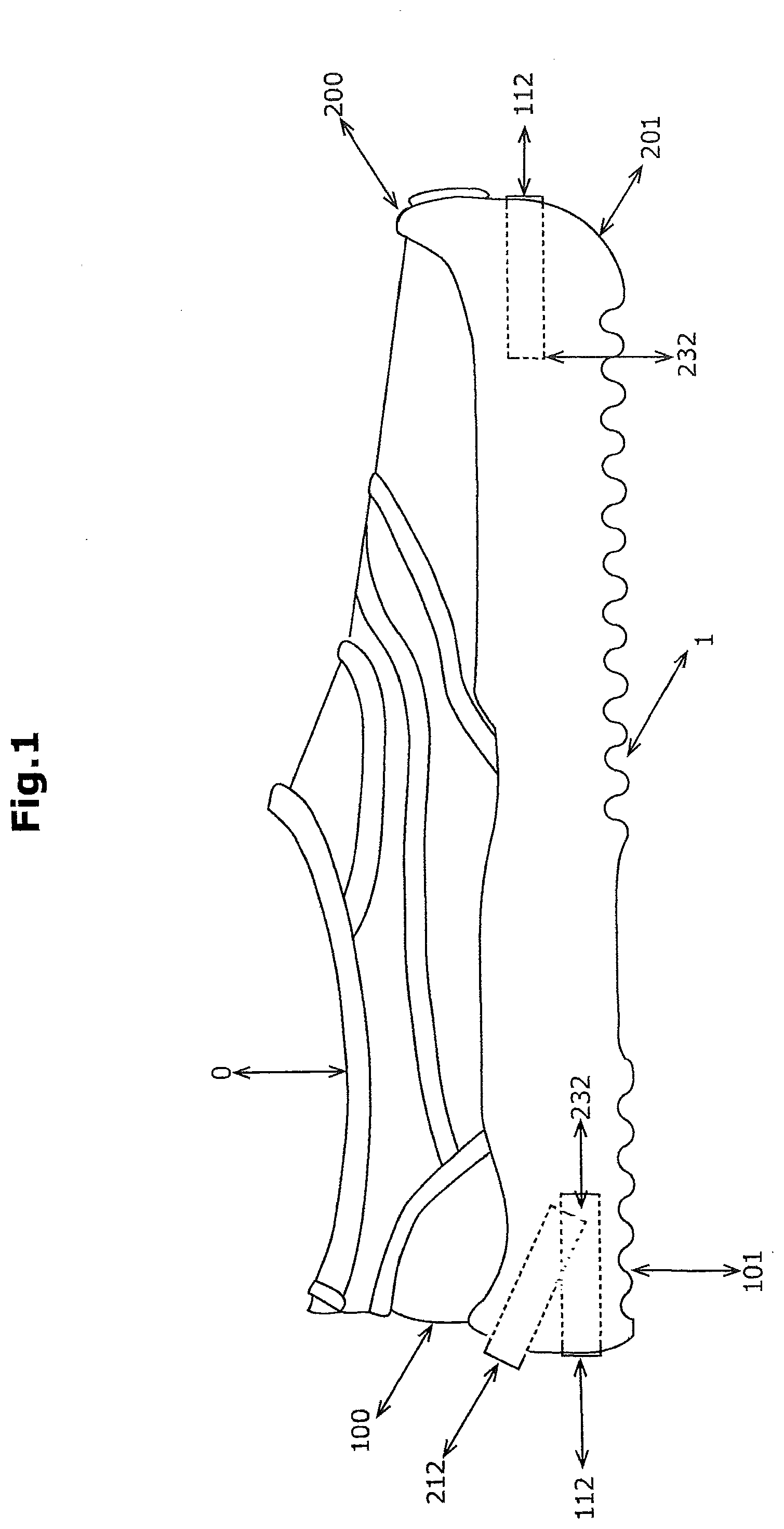
In one embodiment of the invention, the production method preferably comprises the successive steps of fixing the cover including the tube on the duct and then inserting the casing into the hole such that the cover closes the duct and the mouth of the hole. In accordance with another aspect, the invention proposes a footwear item comprising a sole, the sole comprising a rear part, characterised in that the rear part of the sole includes a hole with a level or slanted bottom, following the shape of the sole and opening towards the rear of the footwear item, and in that the footwear item comprises a duct inserted into the hole in the sole, the duct storing information or objects. It is also possible to provide other variants and to have soles including a hole at the front of the footwear item, opening towards the front of the footwear item, or a hole on the outer side of the rear part and opening towards the outside of the footwear item. It is also possible to form this hole on the outside of the footwear item, extending across, with said hole opening towards the outside of the footwear item, in the rear part of the footwear item. The hole extends beyond the footwear item. The hole can be formed in the rear of the sole, increasing the height of the rear of sole in the form of a beading as far as the base of the heel cup, or by increasing the length of the sole. The hole can also be formed in the support by increasing the volume of the neck of the support. Within the scope of the present invention, a footwear item “sole” is a part of the footwear item intended to be situated between the foot of the user of the footwear item and the ground. Further features and advantages of the invention will become clear from reading the following detailed description. Also, in order to provide a clearer understanding of the invention, several preferred embodiments will be described hereinafter by way of example, with reference in particular to the accompanying figures, in which The present invention is described on the basis of particular embodiments and with reference to the figures, however the invention is not limited thereto. The drawings or figures described are merely schematic and are not limiting. The footwear item (0) comprises a sole (1), the rear part (101) of which is visible in The rear part (101) of the sole (1) comprises a hole (2) which opens towards the rear of the footwear item (0). The hole (2) is preferably situated in the heel of the footwear item (0). As can be seen in The casing (3 and 4) has a first face, turned towards the mouth (153) of the hole when the casing is in place inside the hole (2), and a second face, opposite the first face, for closing the casing. The casing (3 and 4) is preferably cylindrical, in which case the casing preferably has a diameter between 0.5 and 2.0 cm, more preferably between 1.0 and 1.5 cm. The casing (3 and 4) preferably has a length between 1.0 and 10.0 cm, more preferably between 3.0 and 7.0 cm, even more preferably between 4.0 and 6.0 cm. The hole (2) is preferably substantially parallel to the inner side of the sole and the duct (3) is preferably also installed so as to be substantially parallel to the inner side of the sole, such that the casing (3 and 4) points towards the rear in a substantially horizontal direction when the footwear item is placed flat on the ground. The footwear item (0) can be a footwear item with a flat heel, with a heel, with a high heel, or with additional soles. The cover (4) has a first face, turned towards the rear when the cover (4) is in place over the mouth (153) of the hole, and a second face, opposite the first face, and thus facing the first face of the casing when the cover (4) closes the hole in which the casing is inserted. The first face and the second face of the cover (4) are separated by a length of the cover. Technical Description of the Duct, and Fixing Thereof: As can be seen in The duct (3) can be provided in different shapes: cylindrical (123), oval (223), rectangular (323), octagonal (423), and can be provided in different sizes. As shown in As shown in As shown in As shown in The duct (3) and also the cover (4) can be made on the basis of any sort of impermeable (metal, aluminium, stainless steel, any sort of plastic, carbon, rubber, etc.). The duct (3) is preferably smooth on the inner face (143) so as to allow the tube incorporating the objects to be easily inserted and removed. The duct (3) is fixed permanently in the sole (1) of the footwear item by anchoring means. In accordance with a preferred embodiment of the invention shown in The bumps (233) then block the duct (3) in the hole (2) and prevent it from being removed, such that the duct (3) is permanently joined to the sole (2). In accordance with the embodiment shown in The duct (3) can be fixed, for example to the sole (1), by another adhesive fixing means, cement, soldering, or by other fusing techniques. In accordance with another preferred embodiment of the invention shown in As can be seen in As can be seen in In accordance with the embodiment shown in In accordance with another preferred embodiment of the invention shown in In accordance with the embodiment shown in The anchoring means of the duct (3) in the presented embodiments can be combined with one another. The hold in the hole of the sole (1) as further reinforced by glue. In accordance with another preferred embodiment of the invention shown in Description and Fixing of the Cover to the Duct: The cover (4) preferably comprises a first fixing part, and the duct (3) comprises a second fixing part, the first and second fixing parts being arranged so as to cooperate together. This makes it possible to obtain a robust and leak-tight fixing between the cover (4) and the duct (3). In a preferred embodiment of the invention shown in The cover (4) comprises flexible toric lamellae (114) on the outer face. By inserting the cover (4) into the duct (3) until the opening of the duct (153) contacts the base of the cover (104), the lamellae (114) can be folded slightly, thus creating a resistance which makes removal of the cover (4) difficult for a child whilst ensuring the tightness of the casing. In order to remove the cover (4), it is suffice for the person to pull strongly on it by means of a grip (414) situated on the base of the cover (104). In a preferred embodiment of the invention shown in This system (134) comprises a pin (1134) connected between a plate (2134), at the lower base (3134), and a lever (4134), at the head of the rod (5134). An O-ring (6134) made of rubber and a blocking piece (7134) in contact with the opening of the duct (153) are positioned between these two parts. When the closing system (134) is in contact with the opening of the duct (153) and therefore the body of the part (8134) is introduced into the duct (3), by pivoting the lever (4134) through 90 degrees relative to the duct 93), the pad (2134) approaches the blocking piece (7134) and thus compresses the rubber O-ring (6134). The diameter of said O-ring increases and thus tightly blocks the lever-based closing system (134) in the duct (3). In a preferred embodiment of the invention, shown in The first screw thread (214) screws into the second screw thread (243) when the cover (4) is screwed to the opening (243) and this screwing makes it possible to obtain a leak-tight fixing, which is easy to open for an adult but is relatively difficult to open for a child. The cover (4) preferably comprises a means (164) for turning the cover (4) relative to the sole (1). This makes the screwing and unscrewing easier. The means (164) for turning the cover relative to the sole comprises a slot (164) intended for the insertion of a coin or a screwdriver. In a preferred embodiment of the invention shown in The cover comprises two lugs (1144). By coupling the duct (3) and the cover (4) woth bayonet-based closing system (144), the two lugs (1144) are in contact with the grooves (443). By pivoting the cover, the two lugs (1144) are blocked in the grooves (443) so as to allow robust fixing between the cover (4) and the duct (3) and for making the casing leak-tight. The cover (4), in accordance with the embodiment shown in In a preferred embodiment of the invention shown in This screwing makes it possible to obtain a robust and leak-tight fixing, which is easy to open for an adult, but relatively difficult to open for a child. The cover (4), in accordance with the embodiment shown in In a preferred embodiment of the invention shown in The cover (4) comprises a rim (204) with a first screw thread on the inner face of the cover (314), and the duct (113) comprises a second screw thread disposed around the mouth of the duct on the outer face (343), so as to correspond to the first screw thread when the cover closes the opening of the duct (153). This screwing makes it possible to obtain a robust and leak-tight fixing, which is easy to open for an adult, but relatively difficult to open for a child. The cover (4), in accordance with the embodiment shown in The base of the cover (104) which contains the slot advantageously has a diameter of 3 mm larger than that of the body of the cover. When the cover (4) is screwed to the duct (3), the base of the cover (104) is in contact with the sole (1) and thus prevents any dirt or liquid from penetrating between the sole (1) and the duct (3). Technical Description of the Tube: In accordance with the preferred embodiments of the invention shown in The tube (5) is preferably inserted into the hole (2) so as to be removable. It is easier to insert documents or objects into the tube (5), and to remove documents or objects therefrom, when said tube is held in the hand. So as to be able to insert and fix the tube (5) more easily into the hole (2) in the sole, this hole (2) is associated with a duct (3) that is preferably sealed on one side and open on the other. In a preferred embodiment of the invention shown in When the cover (4) is fixed on the duct (3), the tube (5) fills the inner part of the duct (3) from one end to the other. The duct (3) and the tube (5) preferably have a length between 1.0 and 10.0 cm, more preferably between 3.0 and 7.0 cm, even more preferably between 4.0 and 6.0 cm. The tube (5) can be made of different materials, such as metal, aluminium, stainless steel, carbon, or a rigid plastics material. The tube (5) preferably can be made of a transparent material so as to be able to see the content thereof. The tube (5) can be fixed removably (205) to the inner face of the cover (154) so as to be able to be detached if desired. In a preferred embodiment of the invention shown in For example, if the grooves (254) are open towards the inner face of the cover, one end of the tube comprises two flat lugs (255) situated outside the tube. By coupling the tube and the cover, the two flat lugs (255) are positioned between the grooves (254). By pivoting the tube in one direction, the two lugs (255) are accommodated and blocked beneath the grooves (254). As can be seen in In accordance with another preferred embodiment of the invention shown in The present invention is not in any way limited to the embodiment described by way of example and shown in the drawings. Numerous modifications of the details, shapes and dimensions could be made without departing from the scope of the invention. The present invention has been described with reference to specific embodiments which are purely illustrative and should not be considered limiting. The reference numbers in the claims do not limit the scope thereof. The invention relates to a footwear item comprising a device for storing information or an object. The footwear item comprises a sole (1) including a front part (201) and a rear part (101), with a hole (2) being provided in the sole (1) that opens onto the front part (200) or the rear part (100) of the footwear item (0). The invention also comprises: a casing (3, 4) inserted into the hole (2) in the sole (1), said casing (3, 4) comprising a duct (3) designed to be inserted into the hole (2) in the sole (1), said duct (3) comprising an opening (153) and being secured in the hole (2) such that the duct (3) is permanently secured to the sole (1); and a cover (4) hermetically sealing the opening (153) in the duct (3) such that the casing (3, 4) is leak-tight, said cover (4) comprising a tube (5) designed to be inserted into the duct (3) through the opening (153) so as to allow the storage of information or an object. 1.-25. (canceled) 26. A footwear item with device for storing information or an object, comprising a sole (1), the sole (1) including a front part (201) and a rear part (101), wherein the sole (1) includes a hole (2) that opens onto the front part (200) or the rear part (100) of the footwear item (0), and in that the footwear item (0) comprises a casing (3, 4) inserted into the hole (2) of the sole (1),
the casing (3, 4) comprising a duct (3) suitable for insertion into the hole (2) in the sole (1), the duct (3) including an opening (153) and being fixed in the hole (2) in the sole (2) so as to secure the duct (3) to the sole (1) permanently, and the duct (3) being equipped with a cover (4), the cover (4) including a tube (5) suitable for insertion into the duct (3) via the opening (153) and allowing the storage of information or an object, characterized in that the cover (4) hermetically closes the opening (153) of the duct (3) in order to make the casing (3, 4) leak-tight, and in that the duct (3) also comprises an anchoring means (233, 333, 433) integrated in the duct (3), the anchoring means (233) being suitable for fixing the duct (3) in the hole (2) in the sole (1) and for securing the duct (3) to the sole (1) permanently, and in that
a) either the opening of the tube is open (245) and the tube (5) is obstructed at the opening by a removable cap (135) making it possible to close and block the information or object disposed in the tube (5), the cap (135) including a cap head (1135) having a diameter slightly larger than the body (2135) of the cap (135) suitable for insertion in said tube (5), b) or the opening of the tube (5) is closed by an end face (145) so as to obtain a closed tube making it possible to close off and block the information or object disposed in the tube (5). 27. The footwear item according to 28. The footwear item according to 29. The footwear item according to 30. The footwear item according to 31. The footwear item according to 32. The footwear item according to 33. The footwear item according to 34. The footwear item according to 35. The footwear item according to 36. Footwear item according to 37. The footwear item according to 38. The footwear item according to 39. The footwear item according to 40. The footwear item according to 41. The footwear item according to 42. The footwear item according to 43. The footwear item according to 44. The footwear item according to 45. The footwear item according to the duct (3) is elongate and cylindrical in shape (123), the hole (2) in the sole (1) also being of a corresponding cylindrical shape (122), as is also the cover (124) and the tube (125); or the duct (3) is elongate and oval in cross section (223), the hole (2) in the sole (1) also being of a corresponding oval cross section (222), as is also the cover (224) and the tube (225); or the duct (3) is elongate and rectangular in cross section (323), the hole (2) in the sole (1) also being of a corresponding rectangular cross section (322), as is also the cover (324) and the tube (325); or the duct (3) is elongate and octagonal in cross section (423), the hole (2) in the sole (1) also being of a corresponding octagonal cross section (422), as is also the cover (424) and the tube (425). 46. A method for producing a footwear item (0) with a device for storing information or an object, the method comprising:
providing a footwear item (0) comprising a sole (1), the sole (1) comprising a front part (201) and a rear part (101), forming a hole (2) that opens onto the front part (200) or the rear part (100) of the footwear item (0), providing a casing (3, 4) comprising a duct (3) including an opening (153), the duct (3) being equipped with a cover (4) hermetically closing the opening (153) of the duct (3) in order to make the casing (3, 4) leak-tight, the casing (3, 4) being dimensioned such that is suitable for insertion into the hole (2), the cover (4) including a tube (5) suitable for insertion into the duct (3) via the opening (153) and allowing the storage of information or an object, inserting the duct (3) into the hole (2) and fixing the duct (3) to the sole (1) in order to secure the duct (3) and the sole (1) permanently, the duct (3) also comprising an anchoring means (233, 333, 433) integrated in the duct (3), the anchoring means (233) being suitable for fixing the duct (3) in the hole (2) in the sole (1) and for securing the duct (3) to the sole (1) permanently, fixing the tube (5) to the cover (4) permanently (105) or removably (205), wherein: a) either the opening of the tube is open (245) and the tube (5) is obstructed at the opening by a removable cap (135) making it possible to close and block the information or object disposed in the tube (5), the cap (135) including a cap head (1135) having a diameter slightly larger than the body (2135) of the cap (135) suitable for insertion in said tube (5), b) or the opening of the tube (5) is closed by an end face (145) so as to obtain a closed tube making it possible to close off and block the information or object disposed in the tube (5), and fixing the cover (4) on the duct (3). 47. The production method according to fixing the cover (4) including the tube (5) to the duct (3), and then inserting the casing (3, 4) into the hole (2) such that the cover (4) closes the duct (3) and the mouth of the hole (3).TECHNICAL FIELD
PRIOR ART
SUMMARY OF THE INVENTION
BRIEF DESCRIPTION OF THE FIGURES
EMBODIMENTS OF THE INVENTION
Summary Part Specification Reference Figure(s) Footwear 0 1, 7 item: rear of the footwear item 100 1 to 6 front of the footwear item 200 1 outer side of the footwear 300 2, 3, 4, 5, 6 item Sole base: 1 1, 7 rear part 101 1, 14, 15 front part 201 1 tail of the sole 301 4 tail of the sole in the 401 3 form of a beading heel cup of the footwear 501 3, 5, 6 item anterior part Hole: 2 2, 3, 4, 5, 7, 14, 15 smooth 102 7, 14 barbs 202 15 horizontal 112 1 slanted 212 1 round 122 8 oval 222 9 rectangular 322 10 octagonal 422 11 hole diameter larger than 132 27, 28 opening hole bottom 232 1 Duct: 3 7, 12 to 17, 22 fully inserted 113 27 slightly outside the sole 213 25 round 123 8 oval 223 9 rectangular 323 10 octagonal 423 11 outer finish of the duct smooth 133 17 bumps 233 12 barbs 333 13, 14, 15 4 pointed elements 433 16 totally smooth interior 143 12, 13, 16, 17 interior with screw thread 243 22 at the end screw thread externally at 343 25, 27 the end groove end 443 23 duct opening 153 7, 12, 13, 16, 17, 22, 25, 27 duct diameter 253 27, 28 obstructed part of the duct 353 12, 13, 16, 17 Cover: 4 7, 22, 24, 25, 26, 27, 29, 30 base of the cover 104 18, 19, 21, 26, 29 to 34 rim of the cover 204 24, 26, 29, 30, 31, 34 toric lamellae 114 18 outer screw thread 214 19, 22, 32, 33 inner screw thread 314 24, 26 cover grip 414 18, 19, 32, 33 round 124 8 oval 224 9 rectangular 324 10 octagonal 424 11 lever-based closing system 134 21 pin 1134 21 pad 2134 21 lower base 3134 21 lever 4134 21 bar head 5134 21 toric joint 6134 21 blocking part 7134 21 body of the part 8134 21 bayonet-type closing system 144 23 two lugs 1144 23 inner face of the cover 154 24, 26, 31, 34 slides, opening towards the 254 31 interior slides, opening towards the 354 34 exterior slot for insertion of a 164 20, 22, 27 screwdriver Tube: 5 7, 18, 19, 21 to 27, 29 to 34 tube with fixed fixing 105 tube with removably fixing 205 29, 3 cover-tube connection 305 18, 19, 21, 32, 33, 34 exterior bayonet-based tube 115 31 fixing interior bayonet-based tube 215 34 fixing round tube 125 8 oval tube 225 9 rectangular tube 325 10 octagonal tube 425 11 removable tube cap 135 30 cap head 1135 30 cap body 2135 30 closed tube 145 29, 32 open tube 245 30, 33 tube with inner lugs 155 34 tube with outer lugs 255 31