GAS DISCHARGE APPARATUS FOR LIQUEFIED HYDROGEN STORAGE TANKS
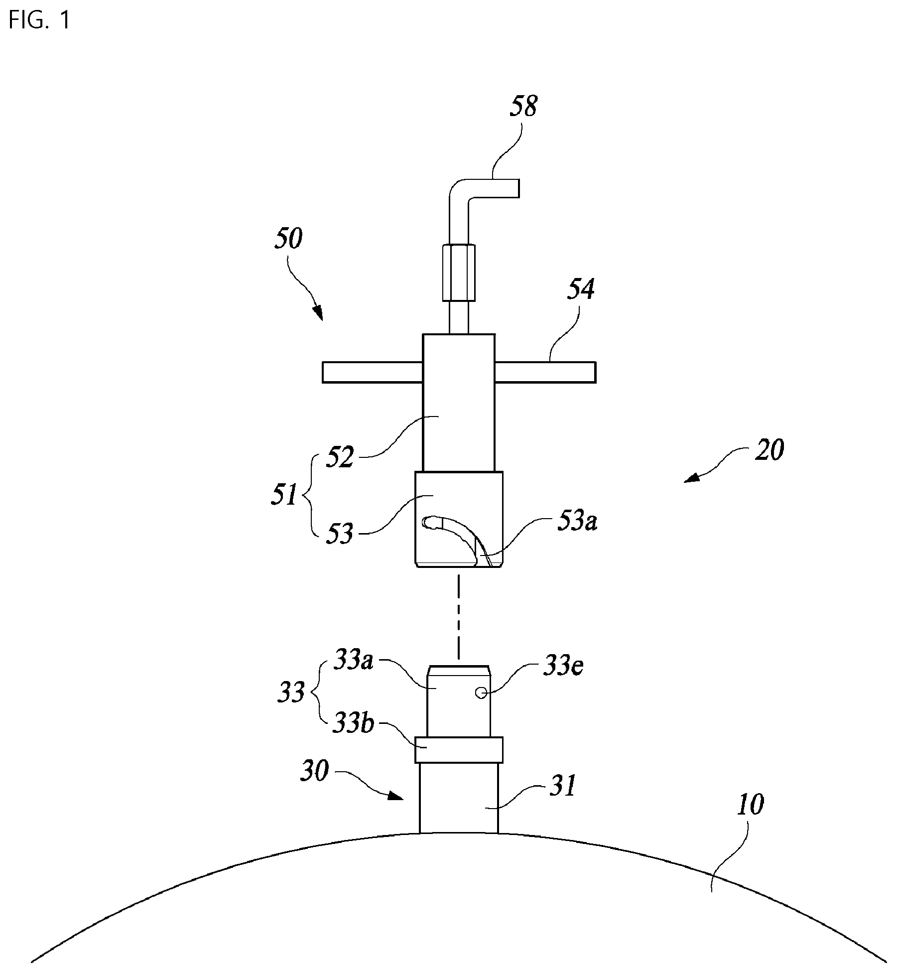
This application claims priority from Korean Patent Application No. 10-2020-0029697, filed on Mar. 10, 2020, in the Korean Intellectual Property Office, the disclosure of which is incorporated herein by reference in its entirety. The present invention relates to a gas discharge apparatus mounted to a liquefied hydrogen storage tank, and more particularly to a gas discharge apparatus for liquefied hydrogen storage tanks capable of discharging evaporated gas generated in a liquefied hydrogen storage tank, thereby guaranteeing safety. Hydrogen, which is a clean energy source, has an advantage in that little pollutant is generated upon combustion. As a result, hydrogen may be applied to various fields, and has attracted considerable attention as driving fuel of a moving means, such as a hydrogen vehicle or a drone, in recent years. In order to more efficiently use hydrogen as fuel, it is important to develop technology capable of safely storing hydrogen. Although hydrogen can be stored in a gaseous or liquid state, it is advantageous to store hydrogen in a liquid state in terms of energy density and transportation efficiency. To this end, a liquefied hydrogen storage tank capable of withstanding ultra-low temperature and high pressure in order to store liquefied hydrogen has been developed. Meanwhile, liquefied hydrogen stored in a liquefied hydrogen storage tank is naturally evaporated little by little for several reasons (e.g. the difference in temperature between the liquefied hydrogen and the open air). The evaporated hydrogen gas increases pressure in the liquefied hydrogen storage tank, whereby durability of the liquefied hydrogen storage tank is deteriorated. Depending on circumstances, the liquefied hydrogen storage tank may explode. Consequently, the hydrogen gas must be frequently discharged from the liquefied hydrogen storage tank in order to prevent pressure in the liquefied hydrogen storage tank from increasing excessively. For this reason, a gas discharge apparatus is generally installed at the liquefied hydrogen storage tank. There are various kinds of conventional gas discharge apparatuses, and hydrogen gas is discharged from the liquefied hydrogen storage tank through the gas discharge apparatus, whereby safety is guaranteed. Korean Patent Application Publication No. 10-2-17-0066871 discloses an evaporated gas discharge apparatus and method. The disclosed discharge apparatus is a mobile evaporated gas discharge apparatus for discharging evaporated gas generated in a liquefied hydrogen storage tank, wherein one end of the discharge apparatus is movable to an isolated evaporated gas zone, in which evaporated gas generated in the storage tank is collected, in order to discharge the evaporated gas in the isolated evaporated gas zone from the storage tank. The present invention has been made in view of the above problems, and it is an object of the present invention to provide a gas discharge apparatus for liquefied hydrogen storage tanks configured such that the maximum value of ejected energy of gas is lowered when being opened, whereby safe treatment is achieved, such that great force is not necessary to perform opening, and such that blocking is also automatically performed by a spring. In accordance with the present invention, the above and other objects can be accomplished by the provision of a gas discharge apparatus for liquefied hydrogen storage tanks, the gas discharge apparatus including a receptacle mounted to a liquefied hydrogen storage tank, the receptacle having a stationary valve configured to be opened by external force mounted therein, a multistage opening and closing device coupled to the receptacle such that the position of the multistage opening and closing device is adjustable, the multistage opening and closing device being configured to be opened by reaction force transmitted from the receptacle when moved relative to the receptacle, the multistage opening and closing device having a sliding valve configured to push open the stationary valve in the state in which the multistage opening and closing device is open, and a manipulation unit configured to move the multistage opening and closing device relative to the receptacle such that the sliding valve and the stationary valve are sequentially opened. The receptacle may include a discharge pipe configured to open an inner space of the liquefied hydrogen storage tank to the outside and a connection tube fixed to an extending end of the discharge pipe, the connection tube defining an outflow channel configured to receive gas passing through the discharge pipe and to guide the received gas to the outside, the connection tube having a stationary valve provided in the outflow channel, the multistage opening and closing device may include an upward-downward movement housing having a rectilinear path located on a straight line of the outflow channel in the state of being coupled to the connection tube, the upward-downward movement housing having the sliding valve provided in the rectilinear path, and the sliding valve may be moved to the stationary valve in the state of being inserted in the outflow channel so as to be joined with the stationary valve and may be opened by reaction force from the stationary valve. The stationary valve may include a valve case fixed in the outflow channel of the connection tube, the valve case having a valve path configured to allow gas to pass therethrough and a step portion formed in the valve path, a driven shutter installed in the valve path such that the position of the driven shutter is adjustable, the driven shutter having a valve stem extending in the longitudinal direction and an opening and closing disc formed integrally with the valve stem, the opening and closing disc being in tight contact with the step portion in order to block the valve path, and a spring installed in the valve path, the spring being configured to elastically support the opening and closing disc against the step portion such that the opening and closing disc blocks the valve path. The sliding valve may include a main body formed so as to have a hollow pipe shape, the main body defining an in-body path configured to allow discharged gas to pass therethrough, a baffle plate located in the in-body path, the baffle plate having a through-hole configured to allow the discharged gas to pass therethrough, a valve body having an extension rod extending in the longitudinal direction, one end of the extension rod being fixed to the baffle plate, the extension rod being located on a straight line of the valve stem, and a blocking disc formed integrally with the extension rod, the blocking disc being formed so as to have a disc shape, a forward-rearward movement cylinder installed in the in-body path so as to be slidable, the forward-rearward movement cylinder having an opening and closing hole configured to allow the extension load to extend therethrough, the opening and closing hole being blocked by the blocking disc, and a spring configured to elastically support the forward-rearward movement cylinder against the valve case such that the opening and closing hole is blocked by the blocking disc in the state in which no external force is applied. The forward-rearward movement cylinder may be formed so as to have a cylindrical shape configured to receive the blocking disc and a portion of the extension rod, the cylindrical shape having a predetermined length, and an end of the forward-rearward movement cylinder may abut the valve case such so as to receive reaction force from the valve case when the multistage opening and closing device is moved to the receptacle. The connection tube may have a predetermined diameter, the connection tube being provided at the outer circumferential surface of an end thereof with a guide pin, the upward-downward movement housing may include a holder configured to receive the end of the connection tube, the holder having a predetermined diameter, and an extension portion formed integrally with the holder, the extension portion having the rectilinear path formed along a central axis thereof, and the holder may be provided with a support slit configured to receive the guide pin and to receive supporting force from the guide pine when the upward-downward movement housing is axially rotated in order to convert axial rotational force of the upward-downward movement housing into rectilinear movement force such that the upward-downward movement housing advances to and retreats from the stationary valve. The support slit may be open to the outside of the holder through a pin entrance and exit portion, the support slit being formed to have a curved shape. A first step recess and a second step recess may be disposed in the support slit so as to be spaced apart from each other, each of the first step recess and the second step recess being configured to allow the guide pin to stay therein, the valve body may be moved to the driven shutter in order to open the opening and closing hole while the guide pin enters the pin entrance and exit portion and reaches the first step recess, and the valve body may push the driven shutter such that the driven shutter is moved in order to open the stationary valve while the guide pin is moved from the first step recess to the second step recess. The manipulation unit may include a handle fixed to the extension portion, the handle being configured to transmit rotational force applied from the outside to the upward-downward movement housing. The receptacle may further have a pipe housing configured to receive the discharge pipe and to support the connection tube. The above and other objects, features and other advantages of the present invention will be more clearly understood from the following detailed description taken in conjunction with the accompanying drawings, in which: Hereinafter, an embodiment of the present invention will be described in more detail with reference to the accompanying drawings. A gas discharge apparatus for liquefied hydrogen storage tanks according to the present invention, which is configured to discharge evaporated gas generated in a liquefied hydrogen storage tank, basically includes a receptacle mounted to a liquefied hydrogen storage tank, the receptacle having a stationary valve configured to be opened by external force mounted therein, a multistage opening and closing device coupled to the receptacle such that the position of the multistage opening and closing device is adjustable, the multistage opening and closing device being configured to be opened by reaction force transmitted from the receptacle when moved relative to the receptacle, the multistage opening and closing device having a sliding valve configured to push open the stationary valve in the state in which the multistage opening and closing device is open, and a manipulation unit configured to move the multistage opening and closing device relative to the receptacle such that the sliding valve and the stationary valve are sequentially opened. As shown, the gas discharge apparatus for liquefied hydrogen storage tanks according to the embodiment of the present invention includes a receptacle 30 and a multistage opening and closing device 50. The receptacle 30 is a structure fixed to a liquefied hydrogen storage tank 10, and has a stationary valve 41 (see The multistage opening and closing device 50 has a sliding valve 55, and serves to discharge gas from the liquefied hydrogen storage tank 10 in the state of being mounted to the receptacle 30. When the multistage opening and closing device 50 is axially rotated in two stages in the state in which to the multistage opening and closing device 50 is mounted to the receptacle 30, the multistage opening and closing device 50 is moved to the receptacle 30 stepwise, whereby gas is discharged from the liquefied hydrogen storage tank 10. The multistage opening and closing device 50 is connected to the receptacle 30 in order to discharge gas from the liquefied hydrogen storage tank 10, and remains separated from the receptacle 30 at ordinary times. A worker moves a liquefied hydrogen storage tank 10 required for gas to be discharged therefrom while holding the multistage opening and closing device 50, and connects the liquefied hydrogen storage tank 10 to a receptacle 30 of the liquefied hydrogen storage tank 10 in order to discharge gas from the liquefied hydrogen storage tank 10. The gas discharged from the liquefied hydrogen storage tank 10 passes through the receptacle 30 and the multistage opening and closing device 50, and is then exhausted to the atmosphere via an extension tube 58. Depending on circumstances, a gas collection apparatus may be connected to the extension tube 58. The receptacle 30 includes a discharge pipe 32 (see The connection tube 33 includes an extension portion 33 In addition, the fixing portion 33 A guide pin 33 The stationary valve 41 is a constantly closed valve mounted in the outflow channel 33 As shown in The valve case 34 is a multistage cylindrical member fixed in the outflow channel 33 The step portion 34 The driven shutter 36 includes a valve stem 36 The spring 35 elastically supports the opening and closing disc 36 Referring back to The upward-downward movement housing 51 has an extension portion 52 and a holder 53. The extension portion 52 is a cylindrical member having a rectilinear path 52 The holder 53 is formed integrally with the extension portion 52, and has a connection tube reception space 53 In addition, a support slit 53 The lower end of the support slit 53 The height A1 from the pin entrance and exit portion 53 Meanwhile, the multistage opening and closing device 50 may be moved relative to the receptacle 30 stepwise, i.e. step by step, by application of the first step recess 53 A first step is a step of the guide pin 33 The lower end of the sliding valve 55 extends to the lower part of the holder 53 in the state in which the sliding valve 55 is received and fixed in the rectilinear path 52 The internal structure of the sliding valve 55 is shown in Referring back to The main body 55 The baffle plate 55 The valve body 55 The forward-rearward movement cylinder 57 is a cylindrical member installed in the in-body path 55 The forward-rearward movement cylinder 57 having the above construction is elastically supported downwards by action of the spring 56. Since the blocking disc 55 Meanwhile, a handle 54, as a manipulation unit, is fixed to the upward-downward movement housing 51. The handle 54 is configured such that a manager rotates the handle in the direction indicated by arrow a or in the opposite direction while holding the handle. The manipulation unit may be variously realized as long as the manipulation unit is capable of rotating the upward-downward movement housing 51. Referring first to In the above state, the guide pin 33 As the guide pin 33 When the upward-downward movement housing 51 is further rotated to move the guide pin 33 As the stationary valve 41 and the sliding valve 55 are opened, as described above, gas in the liquefied hydrogen storage tank 10 is discharged outside via the receptacle 30 and the multistage opening and closing device 50. In order to stop discharge of gas, the upward-downward movement housing 51 is rotated in the opposite direction. As the upward-downward movement housing 51 is rotated in the opposite direction, the stationary valve 41 is blocked, and then the sliding valve 55 is blocked. After blocking of the sliding valve 55 is completed, the multistage opening and closing device 50 is separated from the receptacle 30, and the gas discharge process is finished. As is apparent from the above description, in the gas discharge apparatus for liquefied hydrogen storage tanks according to the present invention constructed as described above, the operation of opening the gas discharge pipe is performed in two stages. Consequently, the maximum value of ejected energy of gas is lowered when the gas discharge pipe is opened, whereby safe treatment is achieved. In addition, the guide pin has a structure capable of moving along the curved support slit. Consequently, great force is not necessary to perform opening, and blocking is also automatically performed by action of the spring, whereby convenience in use is improved. Although the present invention has been described in detail based on the concrete embodiment, those skilled in the art will appreciate that the present invention is not limited thereto and that various modifications, additions, and substitutions are possible without departing from the scope and spirit of the invention as disclosed in the accompanying claims. Disclosed is a gas discharge apparatus for liquefied hydrogen storage tanks, the gas discharge apparatus including a receptacle mounted to a liquefied hydrogen storage tank, the receptacle having a stationary valve configured to be opened by external force mounted therein, a multistage opening and closing device coupled to the receptacle such that the position of the multistage opening and closing device is adjustable, the multistage opening and closing device being configured to be opened by reaction force transmitted from the receptacle when moved relative to the receptacle, the multistage opening and closing device having a sliding valve configured to push open the stationary valve in the state in which the multistage opening and closing device is open, and a manipulation unit configured to move the multistage opening and closing device relative to the receptacle such that the sliding valve and the stationary valve are sequentially opened. 1. A gas discharge apparatus for liquefied hydrogen storage tanks, the gas discharge apparatus comprising:
receptacle mounted to a liquefied hydrogen storage tank, the receptacle having a stationary valve configured to be opened by external force mounted therein; a multistage opening and closing device coupled to the receptacle such that a position of the multistage opening and closing device is adjustable, the multistage opening and closing device being configured to be opened by reaction force transmitted from the receptacle when moved relative to the receptacle, the multistage opening and closing device having a sliding valve configured to push open the stationary valve in a state in which the multistage opening and closing device is open; and a manipulation unit configured to move the multistage opening and closing device relative to the receptacle such that the sliding valve and the stationary valve are sequentially opened. 2. The gas discharge apparatus according to the receptacle comprises: a discharge pipe configured to open an inner space of the liquefied hydrogen storage tank to an outside; and a connection tube fixed to an extending end of the discharge pipe, the connection tube defining an outflow channel configured to receive gas passing through the discharge pipe and to guide the received gas to the outside, the connection tube having a stationary valve provided in the outflow channel, the multistage opening and closing device comprises an upward-downward movement housing having a rectilinear path located on a straight line of the outflow channel in a state of being coupled to the connection tube, the upward-downward movement housing having the sliding valve provided in the rectilinear path, and the sliding valve is moved to the stationary valve in a state of being inserted in the outflow channel so as to be joined with the stationary valve, and is opened by reaction force from the stationary valve. 3. The gas discharge apparatus according to a valve case fixed in the outflow channel of the connection tube, the valve case having a valve path configured to allow gas to pass therethrough and a step portion formed in the valve path; a driven shutter installed in the valve path such that a position of the driven shutter is adjustable, the driven shutter having a valve stem extending in a longitudinal direction and an opening and closing disc formed integrally with the valve stem, the opening and closing disc being in tight contact with the step portion in order to block the valve path; and a spring installed in the valve path, the spring being configured to elastically support the opening and closing disc against the step portion such that the opening and closing disc blocks the valve path. 4. The gas discharge apparatus according to a main body formed so as to have a hollow pipe shape, the main body defining an in-body path configured to allow discharged gas to pass therethrough; a baffle plate located in the in-body path, the baffle plate having a through-hole configured to allow the discharged gas to pass therethrough; a valve body having an extension rod extending in the longitudinal direction, one end of the extension rod being fixed to the baffle plate, the extension rod being located on a straight line of the valve stem, and a blocking disc formed integrally with the extension rod, the blocking disc being formed so as to have a disc shape; a forward-rearward movement cylinder installed in the in-body path so as to be slidable, the forward-rearward movement cylinder having an opening and closing hole configured to allow the extension load to extend therethrough, the opening and closing hole being blocked by the blocking disc; and a spring configured to elastically support the forward-rearward movement cylinder against the valve case such that the opening and closing hole is blocked by the blocking disc in a state in which no external force is applied. 5. The gas discharge apparatus according to the forward-rearward movement cylinder is formed so as to have a cylindrical shape configured to receive the blocking disc and a portion of the extension rod, the cylindrical shape having a predetermined length, and an end of the forward-rearward movement cylinder abuts the valve case such so as to receive reaction force from the valve case when the multistage opening and closing device is moved to the receptacle. 6. The gas discharge apparatus according to the connection tube has a predetermined diameter, the connection tube being provided at an outer circumferential surface of an end thereof with a guide pin, the upward-downward movement housing comprises a holder configured to receive the end of the connection tube, the holder having a predetermined diameter, and an extension portion formed integrally with the holder, the extension portion having the rectilinear path formed along a central axis thereof, and the holder is provided with a support slit configured to receive the guide pin and to receive supporting force from the guide pine when the upward-downward movement housing is axially rotated in order to convert axial rotational force of the upward-downward movement housing into rectilinear movement force such that the upward-downward movement housing advances to and retreats from the stationary valve. 7. The gas discharge apparatus according to 8. The gas discharge apparatus according to a first step recess and a second step recess are disposed in the support slit so as to be spaced apart from each other, each of the first step recess and the second step recess being configured to allow the guide pin to stay therein, the valve body is moved to the driven shutter in order to open the opening and closing hole while the guide pin enters the pin entrance and exit portion and reaches the first step recess, and the valve body pushes the driven shutter such that the driven shutter is moved in order to open the stationary valve while the guide pin is moved from the first step recess to the second step recess. 9. The gas discharge apparatus according to 10. The gas discharge apparatus according to CROSS-REFERENCE TO RELATED APPLICATION
BACKGROUND OF THE INVENTION
1. Field of the Invention
2. Description of the Related Art
SUMMARY OF THE INVENTION
BRIEF DESCRIPTION OF THE DRAWINGS
DETAILED DESCRIPTION OF THE PREFERRED EMBODIMENTS