LIGHT SCANNING APPARATUS AND IMAGE FORMING APPARATUS
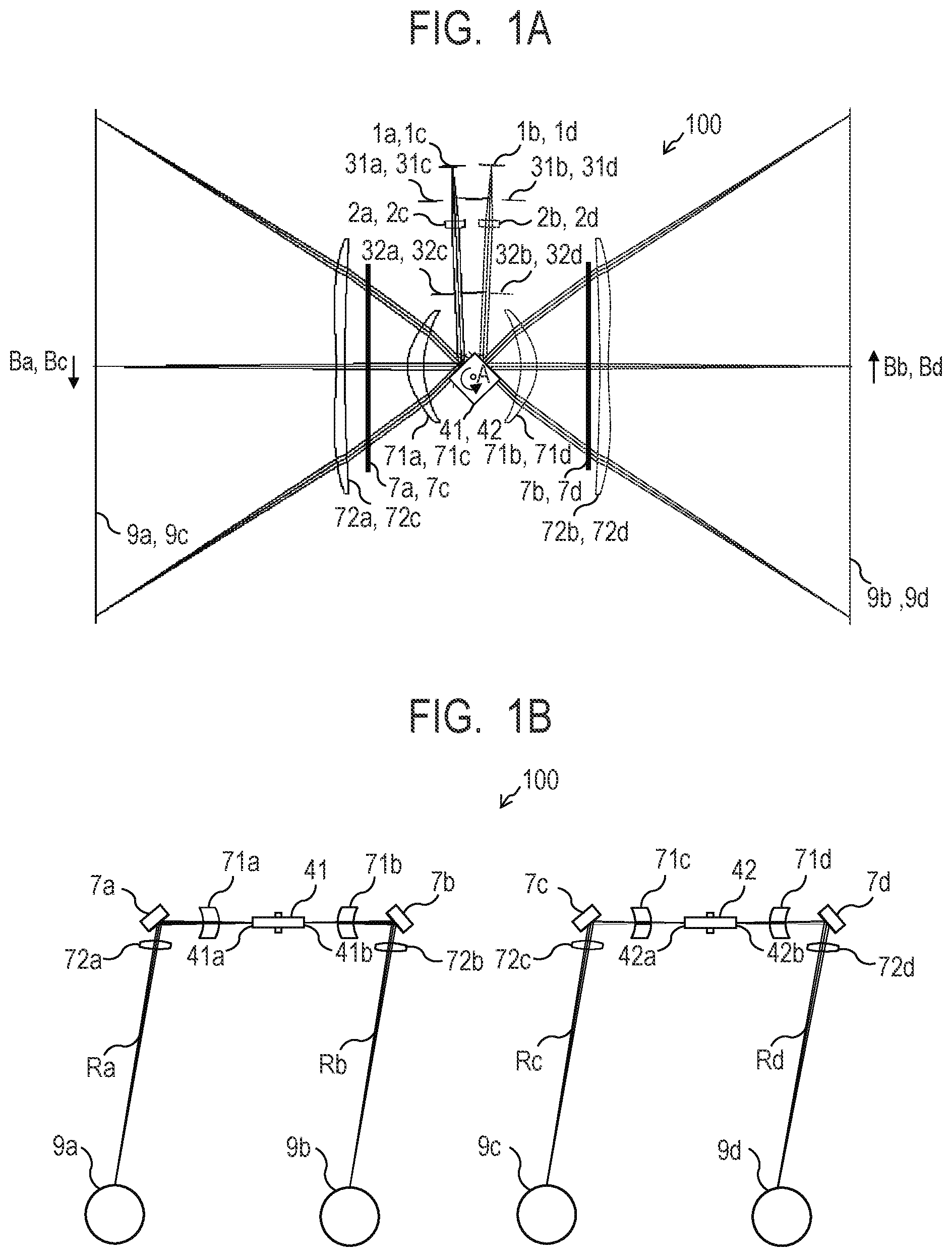
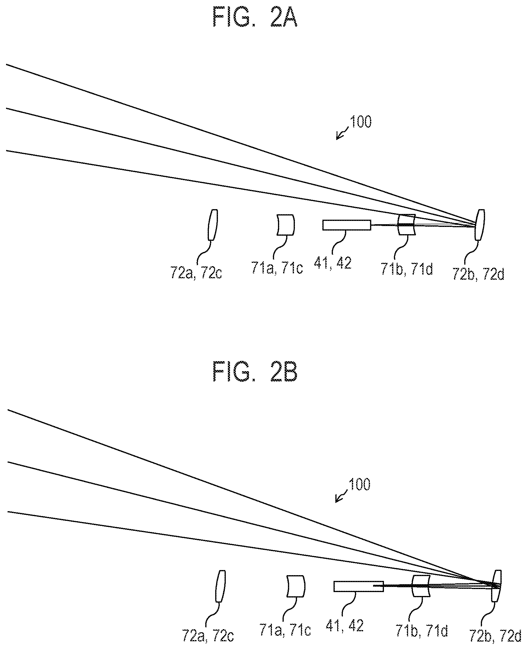
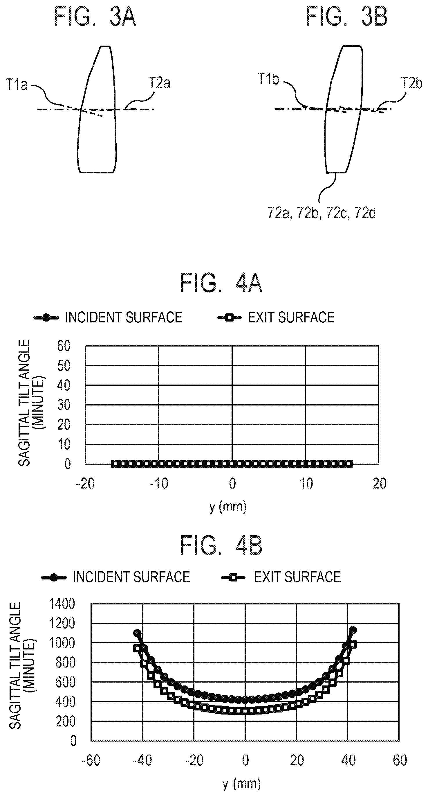
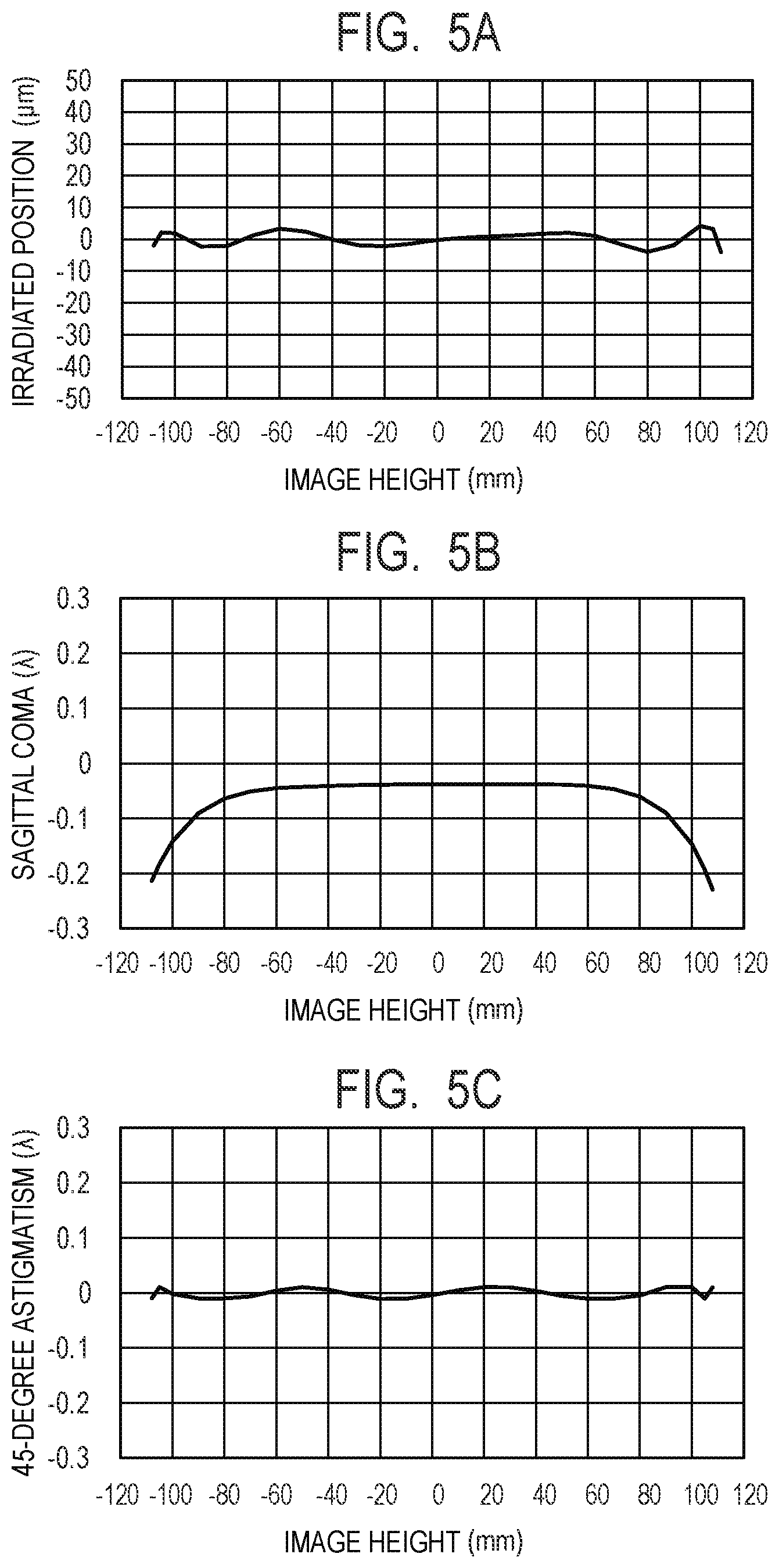
The aspect of the embodiments relates to an optical scanning apparatus, and is more particularly for an image forming apparatus, for example, a laser beam printer (LBP), a digital copying machine, or a multifunction printer (MFP). Hitherto, it has been known that, in a light scanning apparatus, reflection light reflected by an optical surface of an imaging optical element may enter a scanned surface as unnecessary light (ghost) to cause reduction in image quality, or the reflection light may return to a light source via a deflector as unnecessary light (return light) to cause unstable output of the light source. In Japanese Patent Application Laid-Open No. 2004-157205, there is disclosed a light scanning apparatus using an imaging optical element having an optical surface (sagittal tilt surface) whose sagittal line is tilted with respect to an optical axis in order to suppress occurrence of such unnecessary light. In Japanese Patent Application Laid-Open No. 2004-157205, in a configuration (sub-scanning obliquely-incident system) in which light fluxes are caused to obliquely enter the deflector within a sub-scanning cross section, an aspherical surface is provided to correct scanning-line curvature to be caused by the sagittal tilt surface. However, in a configuration in which light fluxes are caused to perpendicularly enter the deflector within the sub-scanning cross section, it is difficult to sufficiently correct reduction in optical performance caused by the sagittal tilt surface by providing one aspherical surface as in Japanese Patent Application Laid-Open No. 2004-157205. Further, the definition expression for the aspherical surface in the sub-scanning cross section described in Japanese Patent Application Laid-Open No. 2004-157205 includes a third-order aspherical coefficient, and hence sensitivity with respect to operation performance in response to light beam vibrations on the imaging optical element is disadvantageously increased. An apparatus including: a first deflector configured to deflect a first light flux from a first light source to scan a first surface in a main scanning direction; and a first imaging optical system which includes a first optical element and a second optical element, and is configured to guide the deflected first light flux to the first surface, wherein, regarding an incident surface and an exit surface of each of the first optical element and the second optical element, when an intersection with an optical axis is set as an origin, an axis parallel to the optical axis is set as an x-axis, an axis perpendicular to the optical axis within a main scanning cross section is set as a y-axis, an axis perpendicular to the optical axis within a sub-scanning cross section is set as a z-axis, an aspherical coefficient is represented by Mm n, a curvature radius within the sub-scanning cross section including the optical axis is represented by r, a variation coefficient is represented by Ei, and shapes within the sub-scanning cross section of the incident surface and the exit surface of each of the first optical element and the second optical element are represented by the following equations: in at least one of the incident surface or the exit surface of the first optical element and each of the incident surface and the exit surface of the second optical element, at least one of values of Mm n is not equal to 0 provided that m is not equal to 0, and wherein the incident surface and the exit surface of the second optical element have M01 of the same sign. Further features of the disclosure will become apparent from the following description of exemplary embodiments with reference to the attached drawings. A light scanning apparatus according to an aspect of the embodiments is described in detail below with reference to the accompanying drawings. Some of the drawings referred to below may be drawn in scales different from the actual scale for easier understanding of the aspect of the embodiments. Hitherto, a light scanning apparatus has been widely used in, for example, a laser beam printer (LBP) and a digital copying machine. In the light scanning apparatus, a light flux optically modulated in accordance with an image signal is emitted from a light source such as a laser, and is periodically deflected by a deflector formed of, for example, a rotary polygon mirror (polygon mirror). Then, the deflected light flux is condensed as a spot onto a photosensitive surface (scanned surface) of a photosensitive member (image bearing member) by an imaging optical system having an fθ characteristic. In this manner, light scans the photosensitive surface to record an image. Further, in the image forming apparatus such as the laser beam printer, the digital copying machine, or a multifunction printer, downsizing and increase in image quality have been demanded. Further, when the image quality of the image forming apparatus is to be increased, it has been known that reflection light from an optical surface of an imaging optical element provided in the imaging optical system of the light scanning apparatus may be one cause of deterioration in image quality. Specifically, the reflection light from the optical surface of the imaging optical element may re-enter the deflector and may return to the light source thereafter. This may cause return light which causes unstable output of the light source. Further, the reflection light from the optical surface of the imaging optical element provided in the imaging optical system may re-enter the deflector and may re-enter the imaging optical system thereafter. This may cause ghost arriving at the scanned surface. Still further, the reflection light from the optical surface of the imaging optical element provided in the imaging optical system may enter an optical path of another imaging optical system arranged on an opposing side. This may cause ghost arriving at even the scanned surface on the opposing side. Yet further, optical elements are arranged close to each other when downsizing is to be achieved. In this case, such return light and ghost are more liable to be caused. In view of the above, in order to reduce such return light and ghost, there has been known a configuration in which the optical surface of the imaging optical element is tilted so as to suppress the entry of the reflection light from the imaging optical element into the optical path. However, when the optical surface of the imaging optical element is tilted as described above, optical performance may be reduced in accordance therewith. In this case, a configuration for correcting the reduced optical performance is also required. The light scanning apparatus according to this embodiment is aimed to ensure sufficient optical performance while suppressing occurrence of return light and ghost. Thus, it is aimed to obtain a light scanning apparatus with which increase in image quality can be achieved, and to obtain an image forming apparatus using the light scanning apparatus. In the following description, a main scanning direction refers to a direction perpendicular to a rotational axis of a deflector (rotary polygon mirror) and an optical axis of an imaging optical system (direction in which a scanned surface is optically scanned by the deflector). A sub-scanning direction refers to a direction parallel to the rotational axis of the deflector. Further, a main scanning cross section refers to a cross section perpendicular to the sub-scanning direction (cross section parallel to the main scanning direction and the optical axis of the imaging optical system). A sub-scanning cross section refers to a cross section perpendicular to the main scanning direction (cross section parallel to the sub-scanning direction and the optical axis of the imaging optical system). As illustrated in The light scanning apparatus 100 according to the first embodiment further includes main scanning stops 32 The light scanning apparatus 100 according to the first embodiment further includes second imaging optical elements 72 The light sources 1 The anamorphic lenses 2 The sub-scanning stops 31 The main scanning stops 32 Accordingly, the incident light fluxes are formed into desired shapes by the sub-scanning stops 31 The deflectors 41 and 42 are each a rotary polygon mirror (polygon mirror) serving as a deflecting unit, and are each configured to rotate at a certain speed in an arrow A direction of The first imaging optical elements 71 The folding mirrors 7 In the light scanning apparatus 100 according to the first embodiment, the sub-scanning stop 31 Further, the sub-scanning stop 31 Further, the sub-scanning stop 31 Further, the sub-scanning stop 31 Further, in the light scanning apparatus 100 according to the first embodiment, the first imaging optical element 71 Further, the first imaging optical element 71 As illustrated in Then, the light fluxes Ra to Rd that have passed through the respective sub-scanning stops 31 Next, the light fluxes Ra to Rd that have passed through the respective anamorphic lenses 2 Then, the light fluxes Ra and Rb that have passed through the respective main scanning stops 32 Further, the light fluxes Rc and Rd that have passed through the respective main scanning stops 32 That is, the first and fourth incident optical systems 75 Then, the light fluxes Ra to Rd emitted from the respective light sources 1 In this manner, the light fluxes Ra to Rd are each condensed within the sub-scanning cross section, and are imaged as long line images in the main scanning direction in the vicinity of the deflecting surfaces 41 Then, the light flux Ra reflected and deflected by the first deflecting surface 41 Then, the light flux Rb reflected and deflected by the second deflecting surface 41 Then, the light flux Rc reflected and deflected by the first deflecting surface 42 Then, the light flux Rd reflected and deflected by the second deflecting surface 42 Then, the deflectors 41 and 42 are rotated in the arrow A direction of Examples of the scanned surfaces 9 In place of the anamorphic lenses 2 Next, various characteristics of the first to fourth incident optical systems 75 In Table 1, E±x means×10±x. Further, coefficients are all 0 unless otherwise noted. In this case, an intersection (lens surface vertex) between each lens surface and an optical axis is set as an origin. An axis parallel to the optical axis is set as an x-axis, an axis perpendicular to the optical axis within the main scanning cross section is set as a y-axis, and an axis perpendicular to the optical axis within the sub-scanning cross section is set as a z-axis. At this time, an aspherical shape (meridional shape) within the main scanning cross section of each of the incident surfaces and the exit surfaces of the first imaging optical elements 71 In this case, R represents a curvature radius, ky represents an eccentricity, and Bi (i=1, 2, 3, . . . , 16) represents an aspherical coefficient. Further, an aspherical shape (sagittal shape) within the sub-scanning cross section of each of the incident surfaces and the exit surfaces of the first imaging optical elements 71 In this case, Mm n (m=0 to 16 and n=1 to 8) represents an aspherical coefficient. Further, a curvature radius r′ within the sub-scanning cross section is successively changed as expressed in the following expression (3) in accordance with the y-coordinate of the lens surface. In this case, r represents a curvature radius within the sub-scanning cross section including the optical axis, and Ei (i=1 to 16) represents a variation coefficient. Further, the following coefficient in the expression (2): can be referred to as an aspherical coefficient in an n-th order sagittal line. In particular, the aspherical coefficient in the first-order sagittal line is represented as follows. This aspherical coefficient can be referred to as a tilt angle (sagittal tilt angle) within the sub-scanning cross section. Further, y=0 is satisfied on the optical axis, and hence the tilt angle within the sub-scanning cross section including the optical axis is represented by M0 1. As shown in Table 1, in the light scanning apparatus 100 according to the first embodiment, the exit surfaces of the first imaging optical elements 71 That is, each optical surface is a sagittal tilt changing surface in which the sagittal tilt angle changes in accordance with the position y in the main scanning direction. In other words, in the exit surfaces of the first imaging optical elements 71 Further, as shown in Table 1, in the incident surfaces and the exit surfaces of the second imaging optical elements 72 That is, the incident surfaces and the exit surfaces of the second imaging optical elements 72 Accordingly, in the incident surfaces and the exit surfaces of the second imaging optical elements 72 Further, in the light scanning apparatus 100 according to the first embodiment, the first imaging optical elements 71 Similarly, the second imaging optical elements 72 Further, in the light scanning apparatus 100 according to the first embodiment, the first imaging optical elements 71 Next, effects in the light scanning apparatus 100 according to the first embodiment are described. As illustrated in Further, the light fluxes Ra to Rd are deflected by the different deflecting surfaces 41 In such a both-side scanning system, reflection light reflected by the optical surface of the imaging optical element provided in one imaging optical system may enter another imaging optical system. As a result, the reflection light reflected by the optical surface of the imaging optical element provided in the one imaging optical system may reach a scanned surface which is not supposed to be scanned, that is, a scanned surface on another side, to thereby cause ghost. Further, the reflection light reflected by the optical surface of the imaging optical element may re-enter the deflectors 41 and 42, and may return to the light source thereafter. This may cause return light which causes unstable output of the light source. In addition, the reflection light reflected by the optical surface of the imaging optical element may re-enter the deflectors 41 and 42 and may be re-deflected thereafter. This may cause ghost arriving at the scanned surface via the imaging optical element. Accordingly, in such a both-side scanning system used in the light scanning apparatus 100 according to the first embodiment, the above-mentioned ghost and return light may cause image defects. In view of the above, in the light scanning apparatus 100 according to the first embodiment, the second imaging optical elements 72 In this manner, as illustrated in each of Accordingly, in the light scanning apparatus 100 according to the first embodiment, the reflection light reflected by the incident surfaces and the exit surfaces of the second imaging optical elements 72 Further, As illustrated in Meanwhile, when such a configuration is to be used in the light scanning apparatus 100 according to the first embodiment using the perpendicularly-incident system, sagittal coma on the optical axis is increased, and thus this configuration is not preferred from the viewpoint of optical performance. In view of the above, in the light scanning apparatus 100 according to the first embodiment, as illustrated in In other words, in the light scanning apparatus 100 according to the first embodiment, the incident surface and the exit surface of each of the second imaging optical elements 72 Further, Further, Various characteristics of the light scanning apparatus according to Comparative Example are shown in Table 2 below. In the light scanning apparatus according to Comparative Example, the sagittal tilt angles are set so that the incident surfaces and the exit surfaces of the second imaging optical elements 72 As shown in As a result, as shown in Further, Further, As shown in Further, as shown in In other words, in the light scanning apparatus 100 according to the first embodiment, when the sagittal tilt angle of each of the exit surfaces of the first imaging optical elements 71 As a result, in the light scanning apparatus 100 according to the first embodiment, as shown in Accordingly, when the above-mentioned configuration is adopted in the light scanning apparatus 100 according to the first embodiment, the optical performance can be satisfactorily corrected while occurrence of ghost and return light to be caused by reflection light reflected by the second imaging optical elements 72 As described above, according to the light scanning apparatus 100 of the first embodiment, reduction of ghost and return light and correction of the optical performance can be both achieved, and thus a satisfactory image can be easily formed when the light scanning apparatus 100 is used in an image forming apparatus. The light scanning apparatus 200 according to the second embodiment has the same configuration as that of the light scanning apparatus 100 according to the first embodiment except that dust-proof glasses 8 Various characteristics of the first to fourth incident optical systems 75 The aspherical shapes of the incident surfaces and the exit surfaces of the first imaging optical elements 71 As illustrated in Further, as shown in Table 3, the dust-proof glasses 8 In this manner, as illustrated in In other words, a normal to the optical surface of each of the dust-proof glasses 8 Further, Further, As shown in Further, as shown in As described above, in the light scanning apparatus 200 according to the second embodiment, the dust-proof glasses 8 In this manner, while the sagittal tilt angle in the vicinity of the most off-axial image height of each of the incident surfaces and the exit surfaces of the second imaging optical elements 72 As described above, according to the light scanning apparatus 200 of the second embodiment, reduction of ghost and return light and correction of the optical performance can be both achieved, and thus a satisfactory image can be easily formed when the light scanning apparatus 200 is used in the image forming apparatus. Consideration is given of a case in which, in a light scanning apparatus as those according to the first and second embodiments in which the optical surface of the imaging optical element is formed of a sagittal tilt changing surface, a multi-beam light source including a plurality of light emitting points is used. At this time, the plurality of light emitting points are arranged so as to be spaced apart from each other in the sub-scanning direction, and hence positions at which principal rays of light fluxes emitted from the respective plurality of light emitting points enter the imaging optical element are spaced apart from each other in the sub-scanning direction. Accordingly, a magnification with respect to each light flux within the main scanning cross section is varied. As a result, an interval between a light condensing point at an axial image height and a light condensing point at the most off-axial image height on the scanned surface to which the light flux is guided is varied among the light fluxes, and thus main scanning jitter occurs. In view of the above, it is aimed to provide a light scanning apparatus with which such main scanning jitter can be suppressed. As illustrated in The light source 1 includes a plurality of light emitting points, and, for example, a semiconductor laser can be used therefor. In the light scanning apparatus 300 according to the third embodiment, as described below, the light source 1 includes four light emitting points. The anamorphic lens 2 is a lens having different positive powers (refractive powers) within the main scanning cross section and the sub-scanning cross section. The anamorphic lens 2 is configured to convert incident light fluxes into substantially parallel light fluxes within the main scanning cross section, and condense the light fluxes in the sub-scanning cross section. In this case, the substantially parallel light fluxes include weakly divergent light fluxes, weakly convergent light fluxes, and parallel light fluxes. The sub-scanning stop 31 is configured to restrict the shape of the incident light fluxes in the sub-scanning direction (light flux width or light flux diameter in the sub-scanning direction). The main scanning stop 32 is configured to restrict the shape of the incident light fluxes in the main scanning direction (light flux width or light flux diameter in the main scanning direction). Accordingly, the incident light fluxes are formed into desired shapes by the sub-scanning stop 31 and the main scanning stop 32. The deflector 6 is a rotary polygon mirror (polygon mirror) serving as a deflecting unit, and is configured to rotate at a certain speed in an arrow A direction of The first imaging optical element 71 and the second imaging optical element 72 are, for example, imaging lenses configured to guide (condense) the incident light fluxes to a scanned surface 9. The dust-proof glass 8 is a flat plate glass having no power and being configured to suppress entry of dust, toner, or the like into the light scanning apparatus 300. In the light scanning apparatus 300 according to the third embodiment, the sub-scanning stop 31, the anamorphic lens 2, and the main scanning stop 32 form the incident optical system 75. Further, in the light scanning apparatus 300 according to the third embodiment, the first imaging optical element 71 and the second imaging optical element 72 form the imaging optical system 85. As illustrated in Then, the light fluxes R that have passed through the sub-scanning stop 31 are converted into substantially parallel light fluxes within the main scanning cross section and condensed in the sub-scanning cross section by the anamorphic lens 2. Next, the light fluxes R that have passed through the anamorphic lens 2 are restricted in shape in the main scanning direction by the main scanning stop 32. Then, the light fluxes R that have passed through the main scanning stop 32 perpendicularly enter a deflecting surface (deflecting and reflecting surface) 6 That is, the incident optical system 75 is arranged so that its optical axis is parallel to the main scanning cross section perpendicular to the rotational axis of the deflector 6. Then, the light fluxes R emitted from the light source 1 enter the deflecting surface 6 In this manner, the light fluxes R are condensed within the sub-scanning cross section, and are imaged as long line images in the main scanning direction in the vicinity of the deflecting surface 6 Then, the light fluxes R reflected and deflected by the deflecting surface 6 Then, the deflector 6 is rotated in the arrow A direction of Examples of the scanned surface 9 include a photosensitive drum surface. In place of the anamorphic lens 2 used in the light scanning apparatus 300 according to the third embodiment, a collimator lens for converting the incident light fluxes into substantially parallel light fluxes and a cylindrical lens for condensing the light fluxes in the sub-scanning cross section may be used. Further, in the light scanning apparatus 300 according to the third embodiment, the anamorphic lens 2, the first imaging optical element 71, and the second imaging optical element 72 are formed of plastic molded lenses. Further, in the light scanning apparatus 300 according to the third embodiment, the imaging optical system 85 is formed of two imaging optical elements, but the disclosure is not limited thereto. Similar effects can be obtained even when the imaging optical system 85 is formed of three or more imaging optical elements. As illustrated in Further, the light emitting points LD1 to LD4 are one-dimensionally arrayed at intervals of 30 μm along a direction forming an angle γ with respect to the main scanning direction, within a cross section which includes the main scanning direction and the sub-scanning direction, and is perpendicular to the optical axis direction. In this case, the light scanning apparatus 300 according to the third embodiment has a configuration capable of changing a rotational angle about the optical axis, that is, the angle γ so that the interval in the sub-scanning direction of the light spots imaged on the scanned surface 9 has a desired size, depending on, for example, the resolution in the sub-scanning direction and manufacturing errors of the incident optical system 75 and the imaging optical system 85. Next, various characteristics of the incident optical system 75 and the imaging optical system 85 of the light scanning apparatus 300 according to the third embodiment are shown in Table 4 below. In the light scanning apparatus 300 according to the third embodiment, a diffraction surface is formed in the incident surface of the anamorphic lens 2, and thus variations in spot diameter due to environmental variations are suppressed. In this case, a phase coefficient of the diffraction surface formed in the incident surface of the anamorphic lens 2 is represented by the following expression (5). In this case, m represents a diffraction order, and Ci j represents a phase coefficient. In the light scanning apparatus 300 according to the third embodiment, the diffraction order m is 1, that is, first-order diffraction light is used. This is beneficial in terms of manufacture, specifically, variations in refractive index and variations in wavelength at the time of temperature rise are canceled out. Further, the aspherical shapes of the incident surfaces and the exit surfaces of the first imaging optical element 71 and the second imaging optical element 72 are represented by the above-mentioned expressions (1) to (3) similarly to the light scanning apparatus 100 according to the first embodiment. Further, as shown in Table 4, in the light scanning apparatus 300 according to the third embodiment, the incident surface of the first imaging optical element 71, the exit surface of the first imaging optical element 71, the incident surface of the second imaging optical element 72, and the exit surface of the second imaging optical element 72 each have a first-order aspherical surface with respect to z. That is, each optical surface is a sagittal tilt changing surface in which the sagittal tilt angle changes in accordance with the position y in the main scanning direction. In other words, in the incident surface of the first imaging optical element 71, the exit surface of the first imaging optical element 71, the incident surface of the second imaging optical element 72, and the exit surface of the second imaging optical element 72, at least one of values of Mm n is not equal to 0 provided that m is not equal to 0. Further, as shown in Table 4, in the incident surface and the exit surface of the second imaging optical element 72, M0 1 is not equal to 0. That is, the incident surface and the exit surface of the second imaging optical element 72 have sagittal tilt angles even on the optical axis. Accordingly, in the incident surface and the exit surface of the second imaging optical element 72, the origin in the shape definition and the surface vertex (most protruding point in the optical axis direction) do not match each other. Next, factors causing main scanning jitter in the related-art light scanning apparatus are described. The related-art light scanning apparatus described here has the same configuration as that of the light scanning apparatus 300 according to the third embodiment except that the various characteristics are different, and hence like members are denoted by like reference symbols to omit the description thereof. Further, As illustrated in At this time, in each of the incident surfaces and the exit surfaces of the first imaging optical element 71 and the second imaging optical element 72, the curvature radius r′ and the sagittal tilt angle within the sub-scanning cross section are changed in accordance with the position y in the main scanning direction. Accordingly, when the light fluxes enter the incident surfaces and the exit surfaces of the first imaging optical element 71 and the second imaging optical element 72 at different heights, the magnification with respect to each light flux within the main scanning cross section is varied. As a result, as illustrated in In view of the above, in the light scanning apparatus 300 according to the third embodiment, the following configuration is adopted to reduce the main scanning jitter amount ΔY. First, a lateral magnification of the incident optical system 75 within the sub-scanning cross section is represented by βs, and a distance on the optical axis from the light source 1 to the sub-scanning stop 31 is represented by Ls. Further, a distance from a deflecting point CO to the scanned surface 9 is represented by Tc. The deflecting point CO (hereinafter referred to as “axial deflecting point”) is a deflecting point on the deflecting surface 6 At this time, in the light scanning apparatus 300 according to the third embodiment, the sub-scanning stop 31 is arranged so as to satisfy the following expression (6). In this manner, a separation amount in the sub-scanning direction of the light fluxes at the time when the light fluxes enter the incident surfaces and the exit surfaces of the first imaging optical element 71 and the second imaging optical element 72 can be reduced. In the light scanning apparatus 300 according to the third embodiment, βs=2.24, Ls=14.4, and Tc=153.85 are obtained, and thus it is understood that the expression (6) is satisfied. Further, in the light scanning apparatus 300 according to the third embodiment, the incident surface and the exit surface of the first imaging optical element 71 closest to the deflector 6 are sagittal tilt changing surfaces. In this case, “the imaging optical element closest to the deflector 6” means an imaging optical element that is optically closest to the deflector 6, that is, an imaging optical element arranged at a position closest to the deflector 6 on the optical path from the deflector 6 to the scanned surface 9. Further, the exit surface of the first imaging optical element 71 has the largest refractive power within the main scanning cross section among the incident surfaces and the exit surfaces of the first imaging optical element 71 and the second imaging optical element 72, and thus the first imaging optical element 71 is suitable for correcting the magnification within the main scanning cross section. The above-mentioned configuration is adopted in the light scanning apparatus 300 according to the third embodiment, and thus a magnification shift within the main scanning cross section to be caused by a difference of the incident positions of the light fluxes in the sub-scanning direction on the second imaging optical element 72 can be reduced. Various characteristics of the light scanning apparatus according to Comparative Example are shown in Table 5 below. In the light scanning apparatus according to Comparative Example, the exit surface of the first imaging optical element 71, the incident surface of the second imaging optical element 72, and the exit surface of the second imaging optical element 72 are sagittal tilt changing surfaces. As shown in As described above, in the light scanning apparatus 300 according to the third embodiment, reduction of ghost and return light and correction of the optical performance including the main scanning jitter can be both achieved, and thus a satisfactory image can be easily formed when the light scanning apparatus 300 is used in the image forming apparatus. Further, As illustrated in The light scanning apparatus 400 according to the fourth embodiment further includes main scanning stops 32 The light sources 1 The collimator lenses 3 The cylindrical lenses 4 The sub-scanning stop 31 The main scanning stop 32 The deflector 6 is a rotary polygon mirror (polygon mirror) serving as a deflecting unit, and is configured to rotate at a certain speed in an arrow A direction of The first imaging optical element 71 The folding mirrors 81 The dust-proof glasses 8 In the light scanning apparatus 400 according to the fourth embodiment, the sub-scanning stop 31 In the light scanning apparatus 400 according to the fourth embodiment, the sub-scanning stop 31 Further, the first imaging optical element 71 and the second imaging optical element 72 Further, the first imaging optical element 71 and the second imaging optical element 72 As illustrated in Then, the light fluxes Ra and Rb that have passed through the respective sub-scanning stops 31 Then, the light fluxes Ra and Rb that have passed through the respective collimator lenses 3 Next, the light fluxes Ra and Rb that have passed through the respective cylindrical lenses 4 Then, the light flux Ra that has passed through the main scanning stop 32 That is, in the light scanning apparatus 400 according to the fourth embodiment, the first and second incident optical systems 75 Further, the light fluxes Ra and Rb emitted from the respective light sources 1 In this manner, the light fluxes Ra and Rb are each condensed within the sub-scanning cross section, and are imaged as long line images in the main scanning direction in the vicinity of the deflecting surface 6 In the light scanning apparatus 400 according to the fourth embodiment, the optical axes of the first and second incident optical systems 75 Then, the light flux Ra reflected and deflected by the deflecting surface 6 Similarly, the light flux Rb reflected and deflected by the deflecting surface 6 Then, the deflector 6 is rotated in the arrow A direction of Examples of the scanned surface 9 Further, As illustrated in Similarly, as illustrated in Further, the light emitting points LD1 Further, the light emitting points LD1 In this case, in the light scanning apparatus 400 according to the fourth embodiment, the angles γa and γb have different signs. As illustrated in Further, on the exit side of the first imaging optical element 71, a first exit surface 712 That is, in the light scanning apparatus 400 according to the fourth embodiment, the first imaging optical element 71 is formed as a multi-level lens through which the light fluxes Ra and Rb pass on the lower side and the upper side in the sub-scanning direction, respectively. Next, various characteristics of the first and second incident optical systems 75 Coefficients are all 0 unless otherwise noted. In the light scanning apparatus 400 according to the fourth embodiment, a diffraction surface is formed in the exit surface of each of the cylindrical lenses 4 Further, a phase coefficient of the diffraction surface formed in the exit surface of each of the cylindrical lenses 4 Further, the aspherical shapes of the incident surfaces and the exit surfaces of the first imaging optical element 71 and the second imaging optical elements 72 Further, in the light scanning apparatus 400 according to the fourth embodiment, similarly to the light scanning apparatus 300 according to the third embodiment, in order to reduce the main scanning jitter amount ΔY, the sub-scanning stops 31 In the light scanning apparatus 400 according to the fourth embodiment, βs=3.1, Ls=9.9, and Tc=240 are obtained, and thus it is understood that the expression (6) is satisfied. In this manner, a separation amount in the sub-scanning direction of the light fluxes at the time when the light fluxes enter the incident surfaces and the exit surfaces of the first imaging optical element 71 and the second imaging optical elements 72 Further, as shown in Table 6, in the light scanning apparatus 400 according to the fourth embodiment, the first incident surface 711 That is, each optical surface is a sagittal tilt changing surface in which the sagittal tilt angle changes in accordance with the position y in the main scanning direction. In other words, in the first incident surface 711 Similarly, the incident surface and the exit surface of the second imaging optical element 72 That is, each optical surface is a sagittal tilt changing surface in which the sagittal tilt angle changes in accordance with the position y in the main scanning direction. In other words, in the incident surface and the exit surface of the second imaging optical element 72 Further, as shown in Table 6, in the light scanning apparatus 400 according to the fourth embodiment, in the first incident surface 711 That is, the first incident surface 711 Accordingly, in the first incident surface 711 Similarly, in the incident surface and the exit surface of the second imaging optical element 72 That is, the incident surface and the exit surface of the second imaging optical element 72 Accordingly, in the incident surface and the exit surface of the second imaging optical element 72 Further, As shown in Further, as shown in In this case, the sagittal tilt angle of the first incident surface 711 At this time, the light scanning apparatus 400 according to the fourth embodiment satisfies the following expression (7) at each position y in the main scanning direction. When the light scanning apparatus 400 according to the fourth embodiment satisfies the expression (7), the separation amount in the sub-scanning direction of the light flux Rb with respect to the folding mirror 81 In this manner, in the light scanning apparatus 400 according to the fourth embodiment, interference accompanying with the arrangement of the optical elements can be suppressed. Further, in the light scanning apparatus 400 according to the fourth embodiment, angles γa and γb satisfy the following expression (8). The angles γa and γb are formed by an arrangement direction of the light emitting points LD1 When the light scanning apparatus 400 according to the fourth embodiment satisfies the expression (8), a difference between the main scanning jitter amounts ΔY caused in the respective scanned surfaces 9 As shown in As described above, when the above-mentioned configuration is adopted in the light scanning apparatus 400 according to the fourth embodiment, the main scanning jitter is reduced, and thus the image quality can be increased. Further, the interference accompanying with the arrangement of the optical elements is suppressed, and hence the apparatus can be formed compact. As described above, according to the light scanning apparatus 400 of the fourth embodiment, even when the obliquely-incident system is used, reduction of ghost and return light and correction of the optical performance including the main scanning jitter can be both achieved, and thus a satisfactory image can be easily formed when the light scanning apparatus 400 is used in the image forming apparatus. According to an aspect of the embodiments, it is possible to provide a light scanning apparatus with which sufficient optical performance can be ensured while occurrence of unnecessary light is suppressed. The color image forming apparatus 360 is a tandem-type color image forming apparatus in which the light scanning apparatus 311 is used to record image information on a surface of a photosensitive drum serving as an image bearing member. The color image forming apparatus 360 includes the light scanning apparatus 311 according to the first embodiment, photosensitive drums 341, 342, 343, and 344 each serving as the image bearing member, developing units 321, 322, 323, and 324, a conveyance belt 351, a printer controller 353, and a fixing unit 354. To the color image forming apparatus 360, color signals of red (R), green (G) and blue (B) output from an external apparatus 352, for example, a personal computer, are input. Those color signals are converted into image data (dot data) of cyan (C), magenta (M), yellow (Y), and black (K) by the printer controller 353 in the apparatus. Then, the acquired pieces of image data are input to the light scanning apparatus 311, and light beams 331, 332, 333, and 334 modulated in accordance with the respective pieces of image data are emitted from the light scanning apparatus 311. Then, those light beams scan, in the main scanning direction, the photosensitive surfaces of the respective photosensitive drums 341, 342, 343, and 344. Then, with the light beams 331, 332, 333, and 334 emitted by the light scanning apparatus 311 based on the respective pieces of image data, latent images of respective colors are formed on the photosensitive surfaces of the corresponding photosensitive drums 341, 342, 343, and 344. After that, the latent images of the respective colors are developed by the developing units 321, 322, 323, and 324 into toner images of the respective colors. Then, the developed toner images of the respective colors are transferred on a recording material (transferred material) conveyed by the conveyance belt 351 in superimposition by a transferring unit (not shown), and the transferred toner images are fixed by the fixing unit 354. Thus, one full-color image is formed. The color image forming apparatus 360 according to this embodiment is configured to record, by the light scanning apparatus 311, image signals (image information) in parallel onto the photosensitive surfaces of the photosensitive drums 341, 342, 343, and 344 corresponding to the respective colors of C, M, Y, and K, to thereby print color images at high speed. That is, in the color image forming apparatus 360 according to this embodiment, as described above, the light scanning apparatus 311 is configured to form the latent images of the respective colors on the corresponding photosensitive drum surfaces through use of the light beams that are based on the respective pieces of image data. After that, the images are transferred in superimposition onto the recording material to form one full-color image. In the color image forming apparatus 360 according to this embodiment, in place of the light scanning apparatus 311 according to the first embodiment, the light scanning apparatus according to the second embodiment may be used. Alternatively, four light scanning apparatus according to the third embodiment or two light scanning apparatus according to the fourth embodiment may be used. Further, as the external apparatus 352, for example, a color image reading apparatus including a CCD sensor may be used. In this case, this color image reading apparatus and the color image forming apparatus 360 form a color digital copying machine. While the disclosure has been described with reference to exemplary embodiments, it is to be understood that the disclosure is not limited to the disclosed exemplary embodiments. The scope of the following claims is to be accorded the broadest interpretation so as to encompass all such modifications and equivalent structures and functions. This application claims the benefit of Japanese Patent Application No., 2020-066473 filed Apr. 2, 2020, and Japanese Patent Application No. 2021-049648 filed Mar. 24, 2021, which are hereby incorporated by reference herein in their entirety. An apparatus including: a deflector deflecting a light flux from a light source to scan a surface in a main scanning direction; and an imaging optical system including first and second optical elements, and guiding the light flux deflected by the deflector to the surface. When sagittal shapes of an incident surface and an exit surface of each of the first and second optical elements are represented by the following equations: in at least one of incident surface or exit surface of first optical element and each of incident surface and exit surface of second optical element, at least one of values of Mm n is not equal to 0 provided that m is not equal to 0, and incident surface and exit surface of second optical element have M01 of the same sign. 1. An apparatus comprising:
a first deflector configured to deflect a first light flux from a first light source to scan a first surface in a main scanning direction; and a first imaging optical system which includes a first optical element and a second optical element, and is configured to guide the deflected first light flux to the first surface, wherein, regarding an incident surface and an exit surface of each of the first optical element and the second optical element, when an intersection with an optical axis is set as an origin, an axis parallel to the optical axis is set as an x-axis, an axis perpendicular to the optical axis within a main scanning cross section is set as a y-axis, an axis perpendicular to the optical axis within a sub-scanning cross section is set as a z-axis, an aspherical coefficient is represented by Mm n, a curvature radius within the sub-scanning cross section including the optical axis is represented by r, a variation coefficient is represented by Ei, and shapes within the sub-scanning cross section of the incident surface and the exit surface of each of the first optical element and the second optical element are represented by the following equations: in at least one of the incident surface or the exit surface of the first optical element and each of the incident surface and the exit surface of the second optical element, at least one of values of Mm n is not equal to 0 provided that m is not equal to 0, and wherein the incident surface and the exit surface of the second optical element have M01 of the same sign. 2. The apparatus according to for at least one of the incident surface or the exit surface of the first optical element and the incident surface of the second optical element are represented by T1 and T2, respectively, the following condition is satisfied at each coordinate on the y-axis:
3. The apparatus according to 4. The apparatus according to wherein a normal to an optical surface of the transmitting member on the optical axis within the sub-scanning cross section is inclined in the same direction as a normal to the incident surface and the exit surface of the second optical element on the optical axis within the sub-scanning cross section. 5. The apparatus according to 6. The apparatus according to an incident optical system configured to cause a second light flux from a second light source to perpendicularly enter a second deflecting surface of the first deflector within the sub-scanning cross section; and a second imaging optical system configured to guide the deflected second light flux deflected by the second deflecting surface to a second surface, wherein the first deflector is configured to deflect the second light flux to scan the second surface in the main scanning direction. 7. The apparatus according to a second deflector configured to deflect a third light flux from a third light source and a forth light flux from a fourth light source to scan a third surface and a fourth surface in the main scanning direction; a third incident optical system and a fourth incident optical system which are configured to cause the third light flux and the forth light flux to perpendicularly enter a first deflecting surface and a second deflecting surface of the second deflector, respectively, within the sub-scanning cross section; and a third imaging optical system and a fourth imaging optical system which are configured to guide the first light flux deflected by the first deflecting surface of the second deflector and the second light flux deflected by the second deflecting surface of the second deflector to the third surface and the fourth surface, respectively. 8. The apparatus according to wherein, in the incident surface and the exit surface of the first optical element, at least one of values of Mm n is not equal to 0 provided that m is not equal to 0, and wherein the following inequality is satisfied:
where βs represents a lateral magnification of the first incident optical system within the sub-scanning cross section, Ls represents a distance on the optical axis from the first light source to the sub-scanning stop, and Tc represents a distance from an axial deflecting point of the first deflector to the first surface. 9. The apparatus according to 10. The apparatus according to 11. The apparatus according to 12. The apparatus according to a second incident optical system configured to cause a second plurality of light fluxes from a second light source including a plurality of light emitting points to obliquely enter the first deflecting surface of the first deflector; and a second imaging optical system configured to guide the second plurality of light fluxes and deflected by the first deflecting surface to a second surface, wherein the first deflector is configured to deflect the second plurality of light fluxes to scan the second surface in the main scanning direction. 13. The apparatus according to 14. The apparatus according to wherein the first plurality of light fluxes enter a first incident surface of the first optical element, and then exit from a first exit surface of the first optical element, wherein the second plurality of light fluxes enter a second incident surface of the first optical element, and then exit from a second exit surface of the first optical element, and wherein, when values obtained by the following expression: for each of the first incident surface and the second incident surface are represented by Ti1 and Ti2, respectively, the following inequality is satisfied at each coordinate on the y-axis:
15. The apparatus according to where γa represents an angle formed by an arrangement direction of the plurality of light emitting points of the first light source with respect to the main scanning direction within a cross section perpendicular to the optical axis, and γb represents an angle formed by an arrangement direction of the plurality of light emitting points of the second light source with respect to the main scanning direction within the cross section perpendicular to the optical axis. 16. An image forming apparatus comprising:
the apparatus of a developing unit configured to develop, as a toner image, an electrostatic latent image formed on the first surface by the apparatus; a transferring unit configured to transfer the developed toner image onto a transferred material; and a fixing unit configured to fix the transferred toner image on the transferred material. 17. An image forming apparatus comprising:
the apparatus of a printer controller configured to convert a signal output from an external apparatus into image data to input the image data to the apparatus.BACKGROUND OF THE DISCLOSURE
Field of the Disclosure
Description of the Related Art
SUMMARY OF THE DISCLOSURE
BRIEF DESCRIPTION OF THE DRAWINGS
DESCRIPTION OF THE EMBODIMENTS
First Embodiment
Configurations and arrangements of incident optical system 75 and imaging optical system 85 Usage wavelength λ (nm) 792 Number of light emitting points n 4 Laser cover glass, thickness d1 (mm) 0.250 Laser cover glass, refractive index n1 1.510 From light emitting point of light d2 (mm) 14.400 source 1 to sub-scanning stop 31 From sub-scanning stop 31 to d3 (mm) 8.801 incident surface of anamorphic lens 2 Anamorphic lens 2, thickness d4 (mm) 3.000 Anamorphic lens 2, refractive index n2 1.528 Incident surface of anamorphic R1m (mm) ∞ lens 2, curvature radius within main scanning cross section Incident surface of anamorphic R1s (mm) ∞ lens 2, curvature radius within sub- scanning cross section Exit surface of anamorphic lens 2, R2m (mm) −13.152 curvature radius within main scanning cross section Exit surface of anamorphic lens 2, R2s (mm) −9.254 curvature radius within sub- scanning cross section From exit surface of anamorphic d5 (mm) 27.499 lens 2 to main scanning stop 32 From main scanning stop 32 to d6 (mm) 30.700 deflection reference point From deflection reference point to d7 (mm) 16.000 incident surface of first imaging optical element 71 First imaging optical element 71, d8 (mm) 6.700 thickness First imaging optical element 71, n3 1.528 refractive index From exit surface of first imaging d9 (mm) 26.373 optical element 71 to folding mirror 7 From folding mirror 7 to incident d10 (mm) 8.890 surface of second imaging optical element 72 Second imaging optical element d11 (mm) 3.500 72, thickness Second imaging optical element n4 1.528 72, refractive index From deflection reference point to (mm) 153.848 scanned surface 9 Incident optical system 75, incident α (degree) 87.500 angle in main scanning direction Incident optical system 75, incident β (degree) 0.000 angle in sub-scanning direction fθ coefficient K (mm/rad) 134.000 Effective scanning angle θ (degree) ±46.18 Effective scanning width W (mm) ±108 Deflector 41, 42, number of Surface 4 surfaces Deflector 41, 42, circumradius Rpol (mm) 10 Deflector 41, 42, center position PX (mm) −5.747 Deflector 41, 42, center position PY (mm) −4.222 Aperture stop diameter Rectangle 2.80 × 1.40 (mm) Lens surface data of imaging optical system 85 First imaging optical Second imaging element 71 optical element 72 Incident Exit Incident Exit surface surface surface surface Meridional R −32.952 −21.329 −800.000 144.020 line ky 0.943 −0.926 0.000 −69.458 B1 0.000E+00 0.000E+00 0.000E+00 0.000E+00 B2 0.000E+00 0.000E+00 0.000E+00 0.000E+00 B3 0.000E+00 0.000E+00 0.000E+00 −5.953E−08 B4 1.031E−05 2.457E−06 0.000E+00 −2.415E−06 B5 0.000E+00 0.000E+00 0.000E+00 −1.438E−10 B6 5.173E−08 1.224E−08 0.000E+00 1.183E−09 B7 0.000E+00 0.000E+00 0.000E+00 1.823E−13 B8 −1.090E−10 3.148E−11 0.000E+00 −4.554E−13 B9 0.000E+00 0.000E+00 0.000E+00 −8.685E−17 B10 9.182E−14 −7.942E−14 0.000E+00 1.084E−16 B11 0.000E+00 0.000E+00 0.000E+00 1.538E−20 B12 0.000E+00 0.000E+00 0.000E+00 −1.149E−20 Sagittal r 13.000 13.000 16.894 −320.127 line E1 0.000E+00 0.000E+00 −4.842E−03 8.622E−02 E2 0.000E+00 −6.358E−04 5.569E−04 4.785E−03 E3 0.000E+00 0.000E+00 −3.947E−06 1.456E−04 E4 0.000E+00 4.580E−06 −1.023E−07 1.378E−06 E5 0.000E+00 0.000E+00 5.384E−09 −7.318E−08 E6 0.000E+00 −8.735E−09 −1.057E−10 −2.906E−09 E7 0.000E+00 0.000E+00 −1.923E−13 −4.267E−11 E8 0.000E+00 −2.814E−12 5.336E−14 −3.470E−13 E9 0.000E+00 0.000E+00 −1.238E−15 8.913E−16 E10 0.000E+00 2.797E−14 1.343E−17 3.877E−16 E11 0.000E+00 0.000E+00 2.885E−19 1.051E−17 E12 0.000E+00 0.000E+00 −7.428E−21 7.829E−20 m0_1 0.000E+00 0.000E+00 1.222E−01 1.244E−01 m1_1 0.000E+00 0.000E+00 4.661E−05 8.506E−05 m2_1 0.000E+00 1.041E−04 4.675E−05 1.532E−05 m3_1 0.000E+00 0.000E+00 −8.712E−08 −3.439E−08 m4_1 0.000E+00 −1.543E−07 −7.620E−08 −1.417E−08 m5_1 0.000E+00 0.000E+00 −9.626E−12 −8.129E−11 m6_1 0.000E+00 −1.918E−09 2.892E−11 −6.270E−12 m7_1 0.000E+00 0.000E+00 2.889E−14 4.491E−14 m8_1 0.000E+00 4.449E−12 −4.935E−16 5.761E−15 Configurations and arrangements of incident optical system 75 and imaging optical system 85 Usage wavelength λ (nm) 792 Number of light emitting points n 4 Laser cover glass, thickness d1 (mm) 0.250 Laser cover glass, refractive index n1 1.510 From light emitting point of light d2 (mm) 14.400 source 1 to sub-scanning stop 31 From sub-scanning stop 31 to d3 (mm) 8.801 incident surface of anamorphic lens 2 Anamorphic lens 2, thickness d4 (mm) 3.000 Anamorphic lens 2, refractive index n2 1.528 Incident surface of anamorphic R1m (mm) ∞ lens 2, curvature radius within main scanning cross section Incident surface of anamorphic R1s (mm) ∞ lens 2, curvature radius within sub- scanning cross section Exit surface of anamorphic lens 2, R2m (mm) −13.152 curvature radius within main scanning cross section Exit surface of anamorphic lens 2, R2s (mm) −9.254 curvature radius within sub- scanning cross section From exit surface of anamorphic d5 (mm) 27.499 lens 2 to main scanning stop 32 From main scanning stop 32 to d6 (mm) 30.700 deflection reference point From deflection reference point to d7 (mm) 16.000 incident surface of first imaging optical element 71 First imaging optical element 71, d8 (mm) 6.700 thickness First imaging optical element 71, n3 1.528 refractive index From exit surface of first imaging d9 (mm) 26.373 optical element 71 to folding mirror 7 From folding mirror 7 to incident d10 (mm) 8.890 surface of second imaging optical element 72 Second imaging optical element d11 (mm) 3.500 72, thickness Second imaging optical element n4 1.528 72, refractive index From deflection reference point to (mm) 153.848 scanned surface 9 Incident optical system 75, incident α (degree) 87.500 angle in main scanning direction Incident optical system 75, incident β (degree) 0.000 angle in sub-scanning direction fθ coefficient K (mm/rad) 134.000 Effective scanning angle θ (degree) ±46.18 Effective scanning width W (mm) ±108 Deflector 41, 42, number of Surface 4 surfaces Deflector 41, 42, circumradius Rpol (mm) 10 Deflector 41, 42, center position PX (mm) −5.747 Deflector 41, 42, center position PY (mm) −4.222 Aperture stop diameter Rectangle 2.80 × 1.40 (mm) Lens surface data of imaging optical system 85 First imaging optical Second imaging optical element 71 element 72 Incident Exit Incident Exit surface surface surface surface Meridional R −37.250 −22.861 −800.000 149.389 line ky 1.727 −0.878 0.000 −65.422 B1 0.000E+00 0.000E+00 0.000E+00 0.000E+00 B2 0.000E+00 0.000E+00 0.000E+00 0.000E+00 B3 0.000E+00 0.000E+00 0.000E+00 −1.001E−07 B4 2.402E−06 −3.158E−07 0.000E+00 −2.286E−06 B5 0.000E+00 0.000E+00 0.000E+00 −1.763E−11 B6 8.392E−08 1.482E−08 0.000E+00 1.090E−09 B7 0.000E+00 0.000E+00 0.000E+00 5.313E−14 B8 −1.736E−10 4.441E−11 0.000E+00 −4.117E−13 B9 0.000E+00 0.000E+00 0.000E+00 −1.841E−17 B10 1.540E−13 −1.002E−13 0.000E+00 1.001E−16 B11 0.000E+00 0.000E+00 0.000E+00 2.646E−21 B12 0.000E+00 0.000E+00 0.000E+00 −1.104E−20 Sagittal r 13.000 13.000 30.334 −33.706 line E1 0.000E+00 0.000E+00 −9.367E−03 9.225E−03 E2 0.000E+00 −2.680E−04 1.441E−03 −4.100E−04 E3 0.000E+00 0.000E+00 −2.391E−05 −1.336E−05 E4 0.000E+00 4.948E−06 9.863E−07 7.357E−07 E5 0.000E+00 0.000E+00 −1.008E−08 1.277E−08 E6 0.000E+00 −2.195E−08 −7.281E−10 −7.738E−10 E7 0.000E+00 0.000E+00 3.100E−11 −6.428E−12 E8 0.000E+00 3.538E−11 −9.319E−13 5.834E−13 E9 0.000E+00 0.000E+00 −1.286E−14 1.505E−15 E10 0.000E+00 −1.458E−14 9.672E−16 −2.618E−16 E11 0.000E+00 0.000E+00 −1.093E−18 −1.204E−19 E12 0.000E+00 0.000E+00 −1.791E−19 4.662E−20 m0_1 0.000E+00 0.000E+00 1.222E−01 8.894E−02 m1_l 0.000E+00 0.000E+00 3.172E−05 7.615E−05 m2_1 0.000E+00 0.000E+00 5.879E−05 4.315E−05 m3_1 0.000E+00 0.000E+00 −1.085E−07 −9.032E−08 m4_1 0.000E+00 0.000E+00 −2.960E−08 −5.956E−09 m5_1 0.000E+00 0.000E+00 1.175E−10 7.432E−11 m6_1 0.000E+00 0.000E+00 4.985E−11 2.577E−11 m7_1 0.000E+00 0.000E+00 −1.595E−14 0.000E+00 m8_1 0.000E+00 0.000E+00 −7.408E−15 0.000E+00 Second Embodiment
Configurations and arrangements of incident optical system 75 and imaging optical system 85 Usage wavelength λ (nm) 792 Number of light emitting points n 4 Laser cover glass, thickness d1 (mm) 0.250 Laser cover glass, refractive index n1 1.510 From light emitting point of light d2 (mm) 14.400 source 1 to sub-scanning stop 31 From sub-scanning stop 31 to d3 (mm) 8.801 incident surface of anamorphic lens 2 Anamorphic lens 2, thickness d4 (mm) 3.000 Anamorphic lens 2, refractive index n2 1.528 Incident surface of anamorphic R1m (mm) ∞ lens 2, curvature radius within main scanning cross section Incident surface of anamorphic R1s (mm) ∞ lens 2, curvature radius within sub- scanning cross section Exit surface of anamorphic lens 2, R2m (mm) −13.152 curvature radius within main scanning cross section Exit surface of anamorphic lens 2, R2s (mm) −9.254 curvature radius within sub- scanning cross section From exit surface of anamorphic d5 (mm) 27.499 lens 2 to main scanning stop 32 From main scanning stop 32 to d6 (mm) 30.700 deflection reference point From deflection reference point to d7 (mm) 16.000 incident surface of first imaging optical element 71 First imaging optical element 71, d8 (mm) 6.700 thickness First imaging optical element 71, n3 1.528 refractive index From exit surface of first imaging d9 (mm) 26.373 optical element 71 to folding mirror 7 From folding mirror 7 to incident d10 (mm) 8.890 surface of second imaging optical element 72 Second imaging optical element d11 (mm) 3.500 72, thickness Second imaging optical element n4 1.528 72, refractive index Dust-proof glass 8, thickness d12 (mm) 1.800 Dust-proof glass 8, refractive index n5 1.510 Dust-proof glass 8, inclination γ (degree) 9.600 From deflection reference point to (mm) 153.848 scanned surface 9 Incident optical system 75, incident α (degree) 87.500 angle in main scanning direction Incident optical system 75, incident β (degree) 0.000 angle in sub-scanning direction fθ coefficient K (mm/rad) 134.000 Effective scanning angle θ (degree) ±46.18 Effective scanning width W (mm) ±108 Deflector 41, 42, number of Surface 4 surfaces Deflector 41, 42, circumradius Rpol (mm) 10 Deflector 41, 42, center position PX (mm) −5.747 Deflector 41, 42, center position PY (mm) −4.222 Aperture stop diameter Rectangle 2.80 × 1.40 (mm) Lens surface data of imaging optical system 85 First imaging optical element Second imaging optical 71 element 72 Incident Exit Incident Exit surface surface surface surface Meridional R −34.167 −21.678 −800.000 138.951 line ky −0.679 −1.061 0.000 −68.124 B1 0.000E+00 0.000E+00 0.000E+00 0.000E+00 B2 0.000E+00 0.000E+00 0.000E+00 0.000E+00 B3 0.000E+00 0.000E+00 0.000E+00 −1.023E−07 B4 7.038E−06 2.828E−06 0.000E+00 −2.328E−06 B5 0.000E+00 0.000E+00 0.000E+00 −3.161E−11 B6 2.360E−08 4.345E−09 0.000E+00 1.131E−09 B7 0.000E+00 0.000E+00 0.000E+00 4.021E−14 B8 −5.712E−11 3.708E−11 0.000E+00 −4.351E−13 B9 0.000E+00 0.000E+00 0.000E+00 −1.380E−17 B10 8.294E−15 −8.422E−14 0.000E+00 1.040E−16 B11 0.000E+00 0.000E+00 0.000E+00 2.135E−21 B12 0.000E+00 0.000E+00 0.000E+00 −1.107E−20 Sagittal r 13.000 13.000 23.647 −49.374 line E1 0.000 0.000 −0.004 0.007 E2 0.000E+00 −4.892E−04 7.283E−04 −1.405E−04 E3 0.000E+00 0.000E+00 −4.008E−06 −7.591E−06 E4 0.000E+00 4.864E−06 1.121E−07 4.467E−08 E5 0.000E+00 0.000E+00 8.167E−10 5.574E−09 E6 0.000E+00 −1.650E−08 −2.397E−10 5.865E−11 E7 0.000E+00 0.000E+00 4.603E−12 −3.988E−12 E8 0.000E+00 2.665E−11 1.015E−13 −7.628E−14 E9 0.000E+00 0.000E+00 −3.681E−15 1.813E−15 E10 0.000E+00 −1.267E−14 4.736E−17 2.266E−17 E11 0.000E+00 0.000E+00 6.333E−19 −3.150E−19 E12 0.000E+00 0.000E+00 −1.958E−20 −1.139E−21 m0_1 0.000E+00 0.000E+00 1.222E−01 1.239E−01 m1_1 0.000E+00 0.000E+00 1.050E−05 3.144E−05 m2_1 0.000E+00 1.423E−04 8.238E−05 3.921E−05 m3_1 0.000E+00 0.000E+00 −5.448E−08 −1.635E−08 m4_1 0.000E+00 −3.019E−07 −1.271E−07 −4.858E−08 m5_1 0.000E+00 0.000E+00 −9.715E−11 −1.158E−10 m6_1 0.000E+00 −1.535E−09 6.320E−11 1.667E−11 m7_1 0.000E+00 0.000E+00 5.118E−14 4.528E−14 m8_1 0.000E+00 3.510E−12 −1.734E−14 −4.154E−15 m9_1 0.000E+00 0.000E+00 −5.088E−18 −3.476E−18 m10_1 0.000E+00 0.000E+00 2.107E−18 4.964E−19 m0_4 0.000E+00 0.000E+00 0.000E+00 −1.377E−04 m1_4 0.000E+00 0.000E+00 0.000E+00 5.070E−06 m2_4 0.000E+00 0.000E+00 0.000E+00 2.746E−07 m3_4 0.000E+00 0.000E+00 0.000E+00 −3.784E−09 m4_4 0.000E+00 0.000E+00 0.000E+00 −1.484E−10 m5_4 0.000E+00 0.000E+00 0.000E+00 8.911E−13 m6_4 0.000E+00 0.000E+00 0.000E+00 3.737E−14 Third Embodiment
Configurations and arrangements of incident optical system 75 and imaging optical system 85 Usage wavelength λ (nm) 792 Number of light emitting points n 4 Laser rotational angle γ (degree) 16 Laser cover glass, thickness d1 (mm) 0.250 Laser cover glass, refractive index n1 1.510 From light emitting point of light d2 (mm) 14.400 source 1 to sub-scanning stop 31 From sub-scanning stop 31 to d3 (mm) 10.400 incident surface of anamorphic lens 2 Anamorphic lens 2, thickness d4 (mm) 3.000 Anamorphic lens 2, refractive index n2 1.528 Incident surface of anamorphic C10 −0.012 lens 2, main phase coefficient Incident surface of anamorphic C01 −0.015 lens 2, sub-phase coefficient Exit surface of anamorphic lens 2, R2m (mm) −32.381 curvature radius within main scanning cross section Exit surface of anamorphic lens 2, R2s (mm) −18.751 curvature radius within sub- scanning cross section From exit surface of anamorphic d5 (mm) 25.900 lens 2 to main scanning stop 32 From main scanning stop 32 to d6 (mm) 30.700 deflection reference point From deflection reference point to d7 (mm) 16.000 incident surface of first imaging optical element 71 First imaging optical element 71, d8 (mm) 6.700 thickness First imaging optical element 71, n3 1.528 refractive index From exit surface of first imaging d9 (mm) 26.373 optical element 71 to folding mirror From folding mirror to incident d10 (mm) 8.890 surface of second imaging optical element 72 Second imaging optical element d11 (mm) 3.500 72, thickness Second imaging optical element n4 1.528 72, refractive index From deflection reference point to (mm) 153.848 scanned surface 9 Incident optical system 75, incident α (degree) 87.500 angle in main scanning direction Incident optical system 75, incident β (degree) 0.000 angle in sub-scanning direction fθ coefficient K (mm/rad) 134.000 Effective scanning angle θ (degree) ±46.18 Effective scanning width W (mm) ±108 Deflector 6, number of surfaces Surface 4 Deflector 6, circumradius Rpol (mm) 10 Deflector 6, center position PX (mm) −5.747 Deflector 6, center position PY (mm) −4.222 Sub-stop diameter Width (mm) 1.28 Main stop diameter Width (mm) 2.80 Lens surface data of imaging optical system 85 First imaging optical Second imaging optical element 71 element 72 Incident Exit Incident Exit surface surface surface surface Meridional R −34.420 −21.765 −800.000 139.423 line ky 0.000 −1.179 0.000 −68.939 B1 0.000E+00 0.000E+00 0.000E+00 0.000E+00 B2 0.000E+00 0.000E+00 0.000E+00 0.000E+00 B3 0.000E+00 0.000E+00 0.000E+00 −1.194E−07 B4 8.682E−06 1.618E−06 0.000E+00 −2.313E−06 B5 0.000E+00 0.000E+00 0.000E+00 3.651E−11 B6 2.298E−08 1.062E−09 0.000E+00 1.118E−09 B7 0.000E+00 0.000E+00 0.000E+00 3.002E−15 B8 −4.937E−11 4.350E−11 0.000E+00 −4.272E−13 B9 0.000E+00 0.000E+00 0.000E+00 −1.074E−17 B10 2.430E−15 −8.671E−14 0.000E+00 1.017E−16 B11 0.000E+00 0.000E+00 0.000E+00 3.012E−21 B12 0.000E+00 0.000E+00 0.000E+00 −1.086E−20 Sagittal r 13.000 13.000 20.100 −78.397 line E1 0.000E+00 0.000E+00 −3.629E−03 1.208E−02 E2 0.000E+00 −6.263E−04 6.127E−04 −2.598E−04 E3 0.000E+00 0.000E+00 −2.506E−06 −1.744E−05 E4 0.000E+00 6.079E−06 7.052E−08 −1.302E−08 E5 0.000E+00 0.000E+00 2.136E−09 1.457E−08 E6 0.000E+00 −2.342E−08 −1.620E−10 2.381E−10 E7 0.000E+00 0.000E+00 1.056E−12 −7.480E−12 E8 0.000E+00 4.329E−11 1.380E−14 −1.649E−13 E9 0.000E+00 0.000E+00 −1.462E−15 2.155E−15 E10 0.000E+00 −2.525E−14 5.373E−17 3.792E−17 E11 0.000E+00 0.000E+00 3.127E−19 −2.450E−19 E12 0.000E+00 0.000E+00 −1.683E−20 −1.686E−21 m0_1 0.000E+00 0.000E+00 1.222E−01 1.250E−01 m1_1 0.000E+00 0.000E+00 −2.554E−05 −2.026E−06 m2_1 5.904E−04 5.636E−04 9.684E−05 4.238E−05 m3_1 0.000E+00 0.000E+00 2.570E−08 6.133E−08 m4_1 −3.626E−06 −1.141E−06 −1.759E−07 −6.762E−08 m5_1 0.000E+00 0.000E+00 −1.998E−11 −1.011E−10 m6_1 6.318E−09 −4.677E−09 1.034E−10 2.828E−11 m7_1 0.000E+00 0.000E+00 2.553E−14 7.097E−14 m8_1 −6.274E−12 9.288E−12 −2.966E−14 −5.017E−15 Configurations and arrangements of incident optical system 75 and imaging optical system 85 Usage wavelength λ (nm) 792 Number of light emitting points n 4 Laser rotational angle γ (degree) 16 Laser cover glass, thickness d1 (mm) 0.250 Laser cover glass, refractive n1 1.510 index From light emitting point of light d2 (mm) 14.400 source 1 to sub-scanning stop 31 From sub-scanning stop 31 to d3 (mm) 10.400 incident surface of anamorphic lens 2 Anamorphic lens 2, thickness d4 (mm) 3.000 Anamorphic lens 2, refractive n2 1.528 index Incident surface of anamorphic C10 −0.012 lens 2, main phase coefficient Incident surface of anamorphic C01 −0.015 lens 2, sub-phase coefficient Exit surface of anamorphic lens R2m (mm) −32.381 2, curvature radius within main scanning cross section Exit surface of anamorphic lens R2s (mm) −18.751 2, curvature radius within sub- scanning cross section From exit surface of d5 (mm) 25.900 anamorphic lens 2 to main scanning stop 32 From main scanning stop 32 to d6 (mm) 30.700 deflection reference point From deflection reference point d7 (mm) 16.000 to incident surface of first imaging optical element 71 First imaging optical element d8 (mm) 6.700 71, thickness First imaging optical element n3 1.528 71, refractive index From exit surface of first d9 (mm) 26.373 imaging optical element 71 to folding mirror From folding mirror to incident surface of second imaging d10 (mm) 8.890 optical element 72 Second imaging optical d11 (mm) 3.500 element 72, thickness Second imaging optical n4 1.528 element 72, refractive index From deflection reference point (mm) 153.848 to scanned surface 9 Incident optical system 75, α (degree) 87.500 incident angle in main scanning direction Incident optical system 75, β (degree) 0.000 incident angle in sub-scanning direction fθ coefficient K (mm/rad) 134.000 Effective scanning angle θ (degree) ±46.18 Effective scanning width W (mm) ±108 Deflector 6, number of surfaces Surface 4 Deflector 6, circumradius Rpol (mm) 10 Deflector 6, center position PX (mm) −5.747 Deflector 6, center position PY (mm) −4.222 Sub-stop diameter Width (mm) 1.28 Main stop diameter Width (mm) 2.80 Lens surface data of imaging optical system 85 First imaging optical element Second imaging optical 71 element 72 Incident Incident surface Exit surface surface Exit surface Meridional R −32.952 −21.329 −800.000 144.020 line ky 0.943 −0.926 0.000 −69.458 B1 0.000E+00 0.000E+00 0.000E+00 0.000E+00 B2 0.000E+00 0.000E+00 0.000E+00 0.000E+00 B3 0.000E+00 0.000E+00 0.000E+00 −5.953E−08 B4 1.031E−05 2.457E−06 0.000E+00 −2.415E−06 B5 0.000E+00 0.000E+00 0.000E+00 −1.438E−10 B6 5.173E−08 1.224E−08 0.000E+00 1.183E−09 B7 0.000E+00 0.000E+00 0.000E+00 1.823E−13 B8 −1.090E−10 3.148E−11 0.000E+00 −4.554E−13 B9 0.000E+00 0.000E+00 0.000E+00 −8.685E−17 B10 9.182E−14 −7.942E−14 0.000E+00 1.084E−16 B11 0.000E+00 0.000E+00 0.000E+00 1.538E−20 B12 0.000E+00 0.000E+00 0.000E+00 −1.149E−20 Sagittal r 13.000 13.000 16.894 −320.127 line E1 0.000E+00 0.000E+00 −4.842E−03 8.622E−02 E2 0.000E+00 −6.358E−04 5.569E−04 4.785E−03 E3 0.000E+00 0.000E+00 −3.947E−06 1.456E−04 E4 0.000E+00 4.580E−06 −1.023E−07 1.378E−06 E5 0.000E+00 0.000E+00 5.384E−09 −7.318E−08 E6 0.000E+00 −8.735E−09 −1.057E−10 −2.906E−09 E7 0.000E+00 0.000E+00 −1.923E−13 −4.267E−11 E8 0.000E+00 −2.814E−12 5.336E−14 −3.470E−13 E9 0.000E+00 0.000E+00 −1.238E−15 8.913E−16 E10 0.000E+00 2.797E−14 1.343E−17 3.877E−16 E11 0.000E+00 0.000E+00 2.885E−19 1.051E−17 E12 0.000E+00 0.000E+00 −7.428E−21 7.829E−20 m0_1 0.000E+00 0.000E+00 1.222E−01 1.244E−01 m1_1 0.000E+00 0.000E+00 4.661E−05 8.506E−05 m2_1 0.000E+00 1.041E−04 4.675E−05 1.532E−05 m3_1 0.000E+00 0.000E+00 −8.712E−08 −3.439E−08 m4_1 0.000E+00 −1.543E−07 −7.620E−08 −1.417E−08 m5_1 0.000E+00 0.000E+00 −9.626E−12 −8.129E−11 m6_1 0.000E+00 −1.918E−09 2.892E−11 −6.270E−12 m7_1 0.000E+00 0.000E+00 2.889E−14 4.491E−14 m8_1 0.000E+00 4.449E−12 −4.935E−16 5.761E−15 Fourth Embodiment
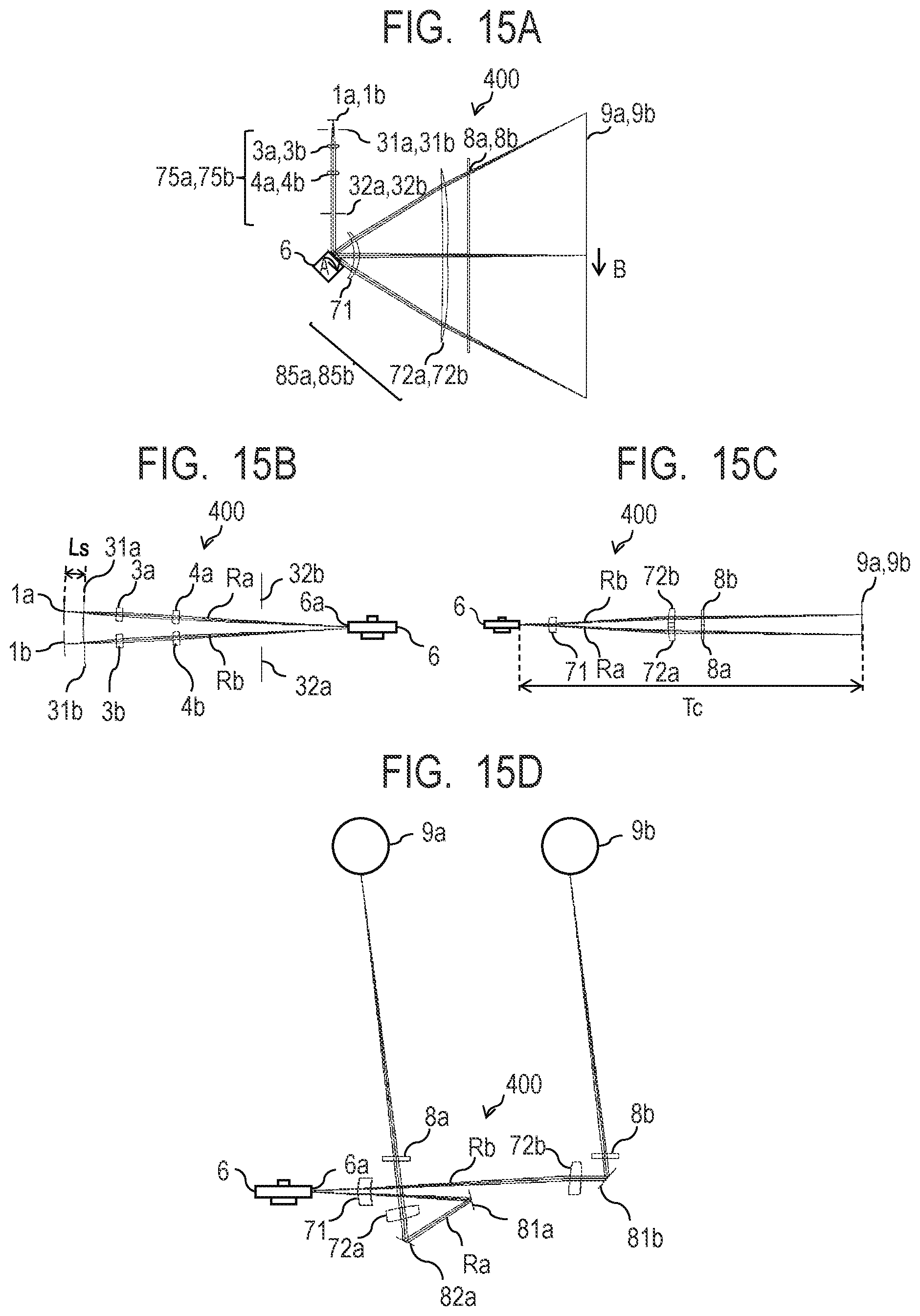
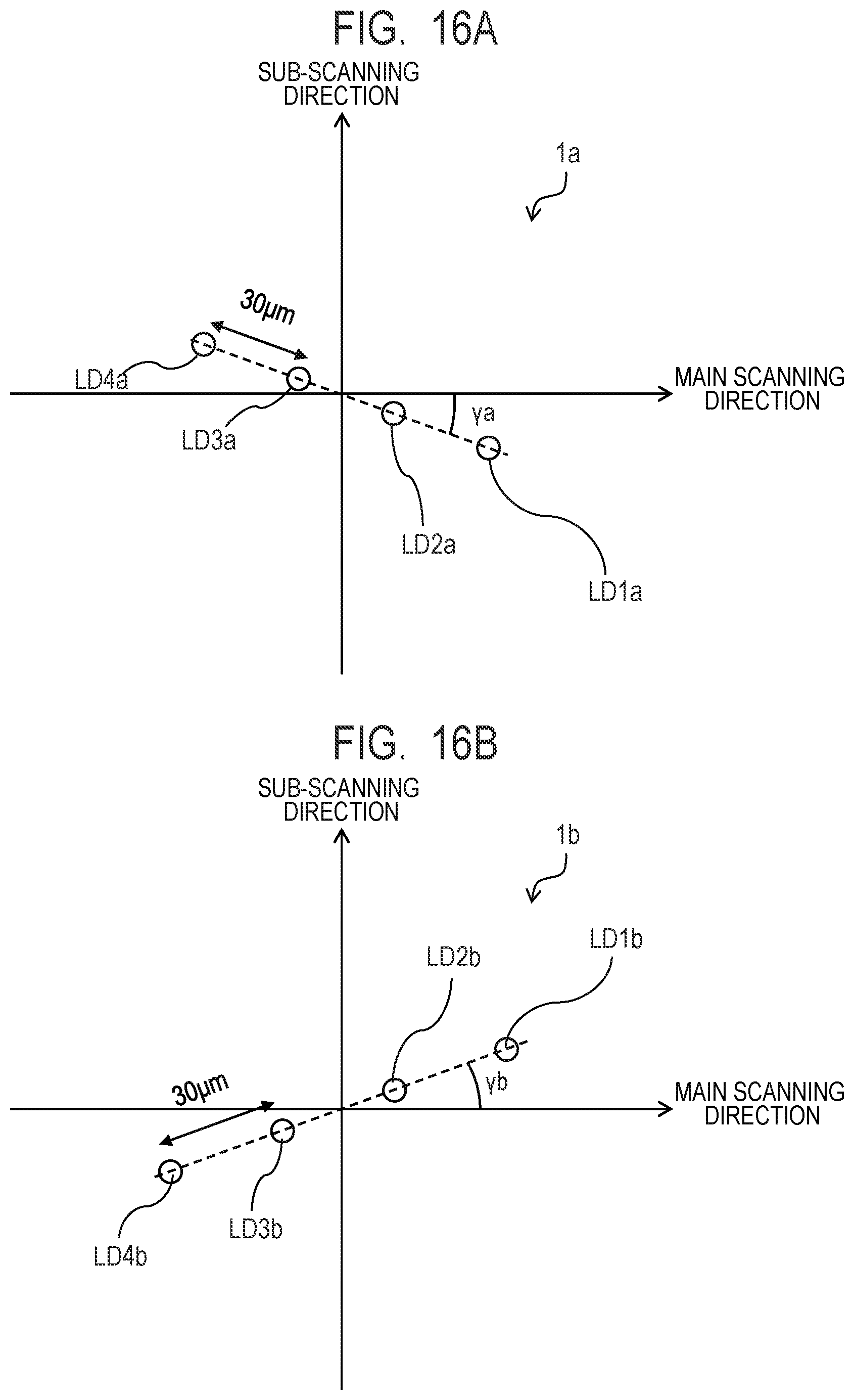
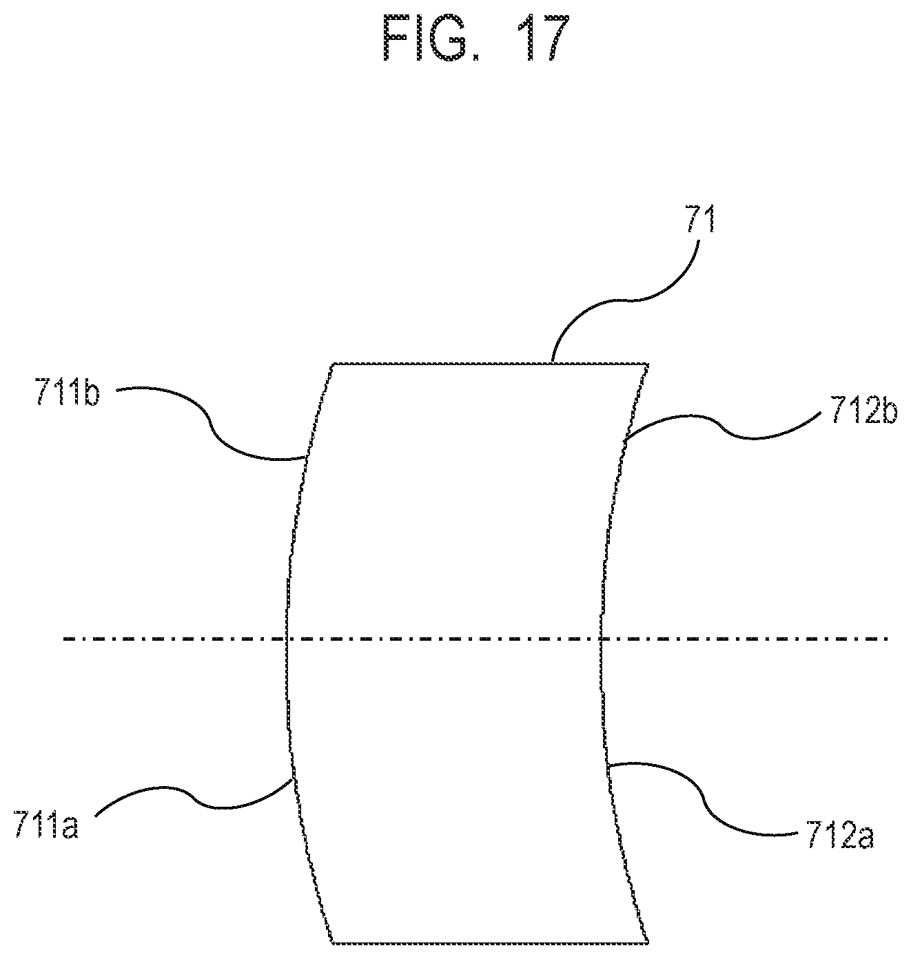
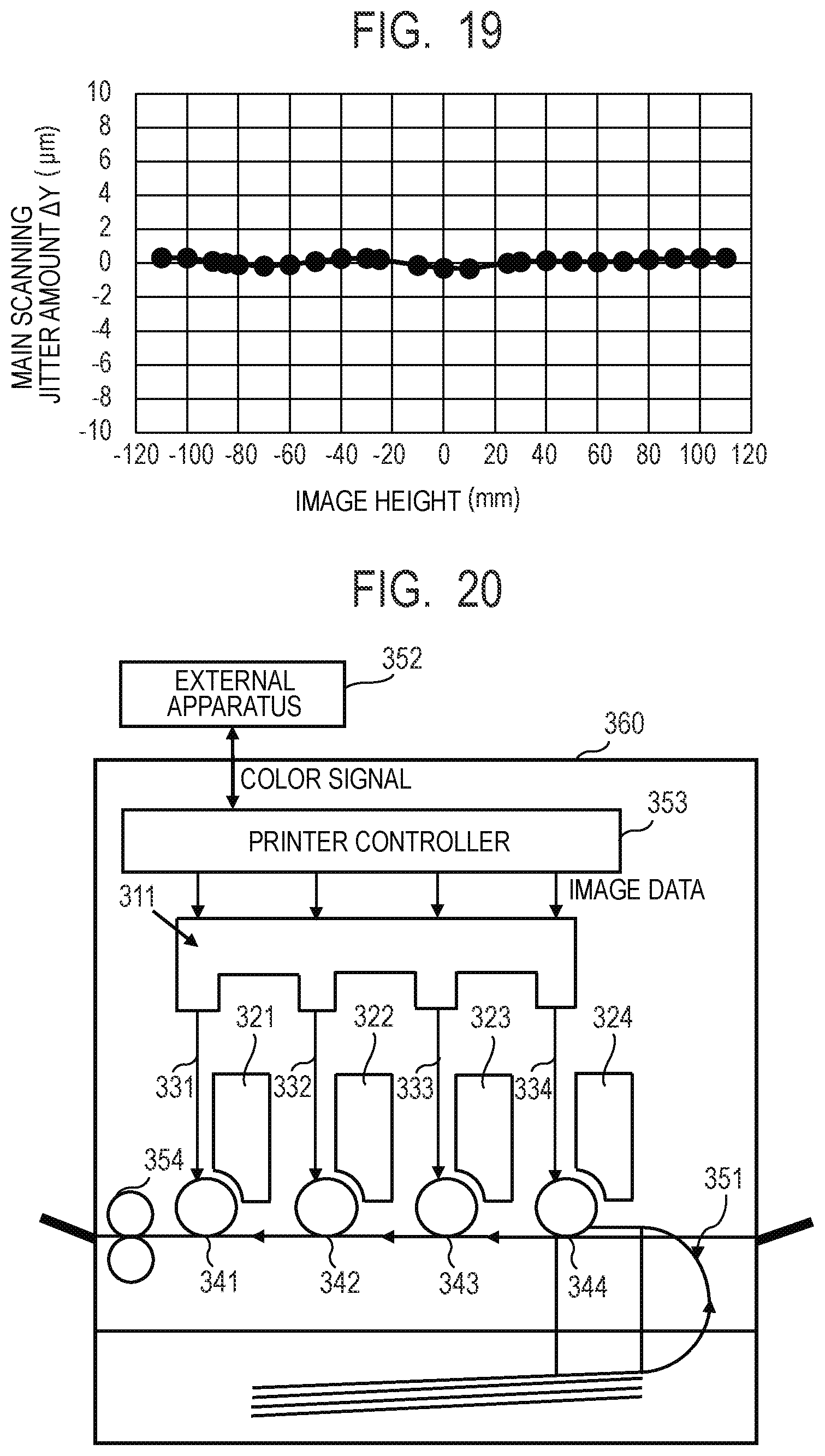
Configurations and arrangements of incident optical system 75 and imaging optical system 85 Usage wavelength λ (nm) 790 Number of light emitting points N 4 Laser rotational angle γ (degree) 20 Laser cover glass, thickness d1 (mm) 0.250 Laser cover glass, refractive index n1 1.510 From light emitting point of light source 1 to sub-scanning stop 31 d2 (mm) 9.900 From sub-scanning stop 31 to incident surface of collimator lens 3 d3 (mm) 23.100 Collimator lens 3, thickness d4 (mm) 3.000 Collimator lens 3, refractive index n2 1.772 Incident surface of collimator lens 3, curvature radius within main R1m (mm) ∞ scanning cross section Incident surface of collimator lens 3, curvature radius within sub- R1s (mm) ∞ scanning cross section Exit surface of collimator lens 3, curvature radius within main scanning R2m (mm) −19.046 cross section Exit surface of collimator lens 3, curvature radius within sub-scanning R2s (mm) −19.046 cross section From exit surface of collimator lens 3 to incident surface of cylindrical d5 (mm) 21.98 lens 4 Cylindrical lens 4, thickness d6 (mm) 3.000 Cylindrical lens 4, refractive index n3 1.528 Incident surface of cylindrical lens 4, curvature radius within main R3m (mm) ∞ scanning cross section Incident surface of cylindrical lens 4, curvature radius within sub- R3s (mm) 58.620 scanning cross section Exit surface of cylindrical lens 4, main phase coefficient C10 0.000 Exit surface of cylindrical lens 4, sub-phase coefficient C01 −0.002 From exit surface of cylindrical lens 4 to main scanning stop 32 d7 (mm) 37.500 From main scanning stop 32 to deflection reference point d8 (mm) 39.500 From deflection reference point to incident surface of first imaging d9 (mm) 20.000 optical element 71 First imaging optical element 71, thickness d10 (mm) 5.000 First imaging optical element 71, refractive index n4 1.528 From exit surface of first imaging optical element 71 to incident d11 (mm) 79.100 surface of second imaging optical element 72 Second imaging optical element 72, thickness d12 (mm) 4.500 Second imaging optical element 72, refractive index n5 1.528 From deflection reference point to scanned surface 9 (mm) 240.000 Incident optical system 75, incident angle in main scanning direction α (degree) 90.000 Incident optical system 75, incident angle in sub-scanning direction β (degree) ±3 fθ coefficient K (mm/rad) 210.000 Effective scanning angle θ (degree) ±30 Effective scanning width W (mm) ±110 Deflector 6, number of surfaces Surface 4 Deflector 6, circumradius Rpol (mm) 10 Deflector 6, center position PX (mm) −5.5 Deflector 6, center position PY (mm) −4.5 Sub-stop diameter Width (mm) 0.6 Main stop diameter Width (mm) 4.0 Second imaging optical element 72, Z shift Z (mm) 5.0 Lens surface data of imaging optical system 85 Second imaging optical Second imaging optical element 72b element 72a First imaging optical element 71 Incident Exit Incident Exit 711b 712b 711a 712a surface surface surface surface Meridlonal R −38.792 −29.471 −38.792 −29.471 −1,848.146 1,487.475 −1,848.146 1,487.475 line ky −0.552 −1.312 −0.552 −1.312 0.000 −2,877.641 0.000 −2,877.641 B1 0.000E+00 0.000E+00 0.000 0.000 0.000E+00 0.000E+00 0.000E+00 0.000E+00 B2 0.000E+00 0.000E+00 0.000 0.000 0.000E+00 0.000E+ 00 0.000E+00 0.000E+00 B3 0.000E+00 0.000E+00 0.000 0.000 0.000E+00 0.000E+00 0.000E+00 0.000E+00 B4 6.358E−06 8.020E−09 0.000 0.000 0.000E+00 −2.440E−07 0.000E+00 −2.440E−07 B5 0.000E+00 0.000E+00 0.000 0.000 0.000E+00 0.000E+00 0.000E+00 0.000E+00 B6 −1.218E−08 −3.955E−09 0.000 0.000 0.000E+00 2.272E−11 0.000E+00 2.272E−11 B7 0.000E+00 0.000E+00 0.000 0.000 0.000E+00 0.000E+00 0.000E+00 0.000E+00 B8 1.345E−11 −1.420E−12 0.000 0.000 0.000E+00 −1.674E−15 0.000E+00 −1.674E−15 B9 0.000E+00 0.000E+00 0.000 0.000 0.000E+00 0.000E+00 0.000E+00 0.000E+00 B10 0.000E+00 4.840E−15 0.000 0.000 0.000E+00 5.532E−20 0.000E+00 5.532E−20 B11 0.000E+00 0.000E+00 0.000 0.000 0.000E+00 0.000E+00 0.000E+00 0.000E+00 B12 0.000E+00 0.000E+00 0.000 0.000 0.000E+00 0.000E+00 0.000E+00 0.000E+00 Saglttall r 20.000 20.000 20.000 20.000 50.382 −75.958 50.382 −75.958 line E1 0.000E+00 0.000E+00 0.000 0.000 0.000E+00 0.000E+00 0.000E+00 0.000E+00 E2 0.000E+00 −4.004E−04 0.000 0.000 0.000E+00 1.510E−04 0.000E+00 1.510E−04 E3 0.000E+00 0.000E+00 0.000 0.000 0.000E+00 0.000E+00 0.000E+00 0.000E+00 E4 0.000E+00 7.394E−07 0.000 0.000 0.000E+00 2.517E−09 0.000E+00 2.517E−09 E5 0.000E+00 0.000E+00 0.000 0.000 0.000E+00 0.000E+00 0.000E+00 0.000E+00 E6 0.000E+00 1.875E−09 0.000 0.000 0.000E+00 1.874E−12 0.000E+00 1.874E−12 E7 0.000E+00 0.000E+00 0.000 0.000 0.000E+00 0.000E+00 0.000E+00 0.000E+00 E8 0.000E+00 0.000E+00 0.000 0.000 0.000E+00 −3.917E−16 0.000E+00 −3.917E−16 E9 0.000E+00 0.000E+00 0.000 0.000 0.000E+00 0.000E+00 0.000E+00 0.000E+00 E10 0.000E+00 0.000E+00 0.000 0.000 0.000E+00 3.122E−20 0.000E+00 3.122E−20 E11 0.000E+00 0.000E+00 0.000 0.000 0.000E+00 0.000E+00 0.000E+00 0.000E+00 E12 0.000E+00 0.000E+00 0.000 0.000 0.000E+00 0.000E+00 0.000E+00 0.000E+00 m0_1 −2.194E−05 −2.051E−05 2.194E−05 2.051E−05 1.046E−01 4.000E−02 −1.046E−01 −4.000E−02 m1_1 0.000E+00 0.000E+00 0.000E+00 0.000E+00 −1.412E−05 −1.858E−05 1.412E−05 1.858E−05 m2_1 −9.715E−05 1.118E−04 9.715E−05 1.118E−04 −9.546E−05 −8.590E−05 9.546E−05 8.590E−05 m3_1 0.000E+00 0.000E+00 0.000E+00 0.000E+00 5.713E−08 5.066E−08 −5.713E−08 −5.066E−08 m4_1 7.973E−07 4.221E−07 −7.973E−07 −4.221E−07 2.243E−08 2.136E−08 −2.243E−08 −2.136E−08 m5_1 0.000E+00 0.000E+00 0.000E+00 0.000E+00 −2.991E−11 −2.391E−11 2.991E−11 2.391E−11 m6_1 4.200E−10 1.112E−09 −4.200E−10 −1.112E−09 −2.296E−12 −3.837E−12 2.296E−12 3.837E−12 m7_1 0.000E+00 0.000E+00 0.000E+00 0.000E+00 6.926E−15 4.662E−15 −6.926E−15 −4.662E−15 m8_1 0.000E+00 0.000E+00 0.000E+00 0.000E+00 −7.773E−16 1.809E−16 7.773E−16 −1.809E−16 m9_1 0.000E+00 0.000E+00 0.000E+00 0.000E+00 −7.033E−19 −2.201E−19 7.033E−19 2.201E−19 m10_1 0.000E+00 0.000E+00 0.000E+00 0.000E+00 1.290E−19 −8.824E−20 −1.290E−19 8.824E−20 [Image Forming Apparatus]
γa/γb≤0,