THERMAL MANAGEMENT SYSTEM FOR BATTERY ELECTRIC VEHICLE
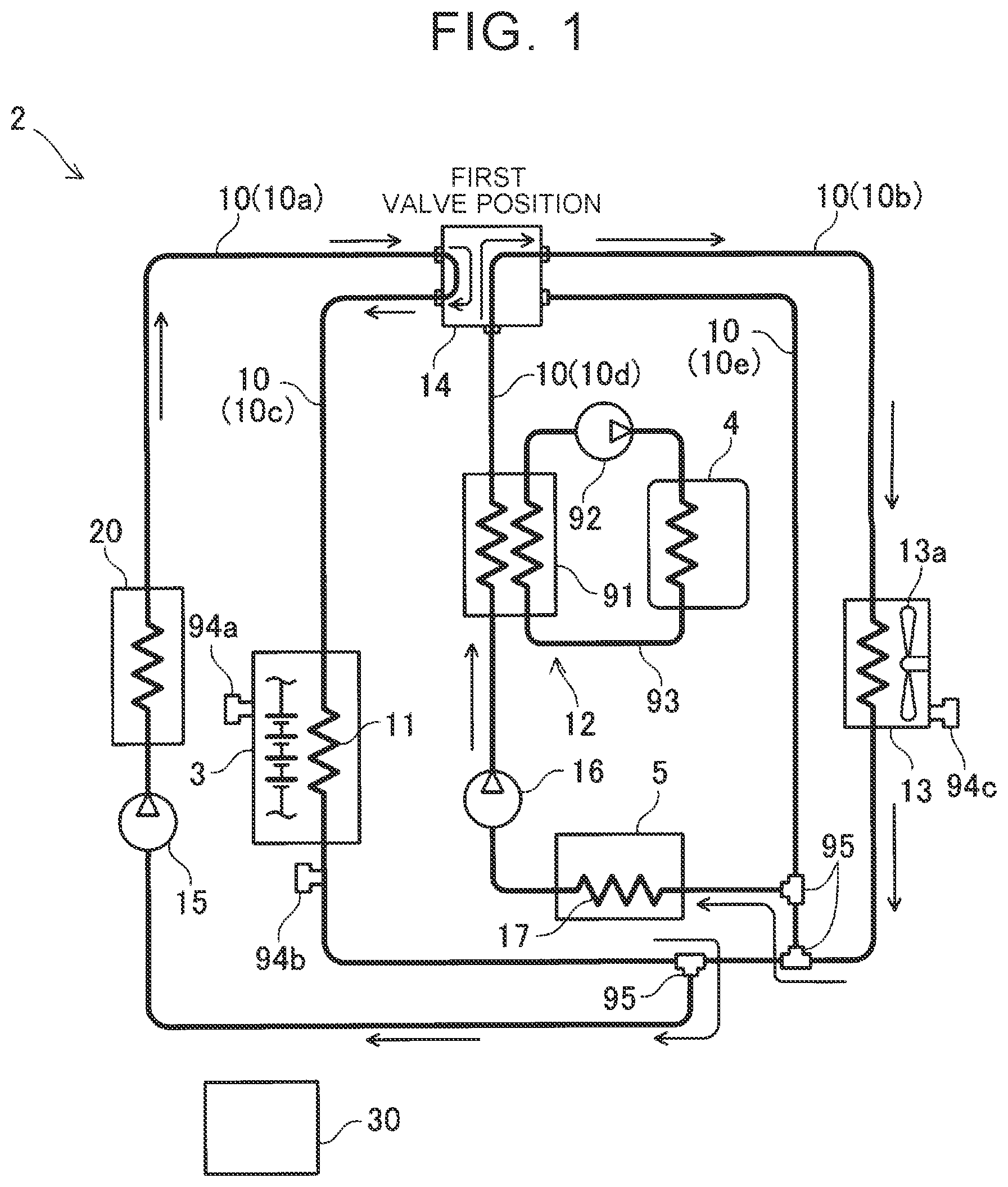
This application claims priority to Japanese Patent Application No. 2021-087096 filed on May 24, 2021, incorporated herein by reference in its entirety. The technique disclosed herein relates to a thermal management system for a battery electric vehicle. There is a thermal management system that uses the heat of the outside air to heat a vehicle cabin. An example of such a thermal management system is disclosed in Japanese Unexamined Patent Application Publication No. 2012-158197 (JP 2012-158197 A). A battery electric vehicle is provided with a power supply that supplies electric power to a motor for traveling. The heat of the power supply can also be used to heat the vehicle cabin. The present disclosure provides a thermal management system that can efficiently use the heat of a power supply and the heat of the outside air to heat a vehicle cabin. A thermal management system according to one aspect of the disclosure includes a power supply that supplies electric power to a motor for traveling; a power supply cooler that cools the power supply with a heat medium; a heater that heats a vehicle cabin with heat of the heat medium; an outside air heat exchanger that exchanges heat between the heat medium and outside air; a circulation path that connects the power supply cooler, the heater, and the outside air heat exchanger; a switching valve located in the circulation path; and a controller configured to control the switching valve. The switching valve is configured to be selectively switched between a first valve position and a second valve position. When the switching valve is in the first valve position, the heat medium circulates between the heater and the power supply cooler, and a flow of the heat medium is cut off between the heater and the outside air heat exchanger. When the switching valve is in the second valve position, the heat medium circulates between the heater and the outside air heat exchanger, and the flow of the heat medium is cut off between the heater and the power supply cooler. The controller is configured to, in a heating mode in which the heater is operated, control the switching valve to select the first valve position when a power supply temperature that is a temperature of the power supply is higher than a predetermined power supply temperature threshold, and control the switching valve to select the second valve position when the power supply temperature is equal to or lower than the power supply temperature threshold. The controller is configured to switch the switching valve from the first valve position to the second valve position regardless of the power supply temperature, when a temperature of the heat medium that has passed through the power supply cooler is lower than an outside air temperature by a predetermined margin temperature difference or more while the switching valve is in the first valve position. When the power supply temperature is higher than the power supply temperature threshold, the first valve position is selected (i.e., the switching valve is in the first valve position) and the heat medium circulates between the heater and the power supply cooler. The heat medium absorbs heat from the high-temperature power supply and heats air in the vehicle cabin through the heater. When the temperature of the power supply is high, heat of the power supply is used for heating. On the other hand, when the temperature of the power supply is equal to or lower than the power supply temperature threshold, the second valve position is selected (i.e., the switching valve is in the second valve position) and the heat medium circulates between the heater and the outside air heat exchanger. The heat medium absorbs heat from the outside air and heats the air in the vehicle cabin through the heater. When the temperature of the power supply is low, heat of the outside air is used for heating. A heat pump mechanism may be used to transfer the heat of the power supply or the outside air to the vehicle cabin. The heat pump mechanism will be described in an embodiment. The controller switches the switching valve from the first valve position to the second valve position regardless of the power supply temperature, when the temperature of the heat medium that has passed through the power supply cooler is lower than the outside air temperature by the predetermined margin temperature difference or more while the switching valve is in the first valve position. For example, heat may not be transferred well from the power supply to the heat medium when a heat transfer sheet sandwiched between the power supply and the power supply cooler deteriorates or when a gap appears between the power supply and the power supply cooler due to vibration of the vehicle. Even when the power supply temperature is not low, the controller switches to heating using the heat of the outside air when heat is not transferred well from the power supply to the heat medium. By controlling the switching valve in this manner, the heat of the power supply and the heat of the outside air can be efficiently used to heat the vehicle cabin. The controller may be configured to hold the switching valve in the second valve position for at least a predetermined holding time regardless of the power supply temperature, when the temperature of the heat medium that has passed through the power supply cooler is lower than the outside air temperature by the margin temperature difference or more. Hunting of the switching valve can thus be prevented. Details and further improvements of the technique disclosed herein will be described in the “DETAILED DESCRIPTION OF EMBODIMENTS” section below. Features, advantages, and technical and industrial significance of exemplary embodiments of the disclosure will be described below with reference to the accompanying drawings, in which like signs denote like elements, and wherein: A thermal management system 2 of an embodiment will be described with reference to the drawings. The thermal management system 2 is mounted on a battery electric vehicle. The thermal management system 2 adjusts the temperature of a vehicle cabin and keeps the temperatures of a power supply 3, a motor for traveling 4, and a power converter 5 within their appropriate temperature ranges. The electric power of the power supply 3 is converted to alternating current (AC) power suitable for driving the motor 4 by the power converter 5, and is supplied to the motor 4. The power supply 3 is typically a battery such as a lithium-ion battery, or a fuel cell, but may be other kinds of power supply. Power lines are not shown in The thermal management system 2 includes a circulation path 10 through which a heat medium flows; a power supply cooler 11 configured to cool the power supply 3; a motor cooler 12 configured to cool the motor 4; an outside air heat exchanger 13 configured to exchange heat between the heat medium and the outside air; an air conditioner 20 configured to adjust the temperature of the vehicle cabin; pumps 15, 16 configured to discharge the heat medium; and a switching valve 14 configured to switch the flow path for the heat medium. The circulation path 10 is a pipe connecting the power supply cooler 11, the motor cooler 12, the outside air heat exchanger 13, the air conditioner 20, and the switching valve 14, and circulates the heat medium between the coolers and the air conditioner. For convenience of description, the circulation path 10 is divided into the following flow paths: an air conditioner flow path 10 The air conditioner 20 adjusts the temperature of the vehicle cabin. The air conditioner 20 operates in two modes including a cooling mode in which the air conditioner 20 cools the vehicle cabin, and a heating mode in which the air conditioner 20 heats the vehicle cabin. The air conditioner 20 is shown in a simplified manner in The power supply cooler 11 cools the power supply 3. The heat medium passing through the power supply cooler 11 absorbs the heat of the power supply 3 to cool the power supply 3. The outside air heat exchanger 13 includes a fan 13 The motor cooler 12 includes an oil cooler 91, an oil pump 92, and an oil flow path 93. The motor cooler flow path 10 The thermal management system 2 includes temperature sensors 94 The measured values of the temperature sensors 94 First ends of the air conditioner flow path 10 The switching valve 14 can be selectively switched between a first valve position and a second valve position (i.e., the position of the switching valve 14 can be selected between the first valve position and the second valve position). As described earlier, when the heating mode is selected, the air conditioner 20 heats the vehicle cabin. The heat of the power supply 3 or the heat of the outside air is used to heat the vehicle cabin. The controller 30 compares the power supply temperature with a power supply temperature threshold (step S5). The power supply temperature is acquired by the temperature sensor 94 As shown in As shown in As described above, the thermal management system 2 heats the vehicle cabin with the heat of the power supply 3 when the temperature of the power supply 3 is high, and heats the vehicle cabin with the heat of the outside air when the temperature of the power supply 3 is low. As described below, however, even when the power supply temperature is high, the thermal management system 2 switches to heating with the heat of the outside air when heat is not transferred well from the power supply 3 to the heat medium. For example, heat may not be transferred well from the power supply to the heat medium when a heat transfer sheet sandwiched between the power supply and the power supply cooler deteriorates or when a gap appears between the power supply and the power supply cooler due to vibration of the vehicle. After selecting the first valve position in step S6, the controller 30 compares the temperature of the heat medium that has passed through the power supply cooler 11 with the outside air temperature (step S8). The temperature of the heat medium that has passed through the power supply cooler 11 is acquired by the temperature sensor 94 When the temperature of the heat medium that has passed through the power supply cooler 11 is lower than the outside air temperature by a predetermined margin temperature difference or more (step S8: YES), the controller 30 switches the switching valve 14 from the first valve position to the second valve position regardless of the power supply temperature (step S9). The controller 30 holds the switching valve 14 in the first valve position when the temperature of the heat medium that has passed through the power supply cooler 11 is not lower than the outside air temperature by the predetermined margin temperature difference or more (step S8: NO). As described above, when the switching valve 14 is set to the second valve position, the heat of the outside air is used to heat the vehicle cabin. The margin temperature difference is set to, for example, 5 degrees. When the temperature of the heat medium that has passed through the power supply cooler 11 is lower than the outside air temperature by 5 degrees or more, the controller 30 switches from heating with the heat of the power supply (first valve position) to heating with the heat of the outside air (second valve position). That is, when the temperature of the heat medium that is supplied to the air conditioner 20 becomes lower than the outside air temperature by the margin temperature difference or more while the switching valve 14 is in the first valve position, the controller 30 switches the switching valve 14 to the second valve position to switch to heating with the heat of the outside air. When the determination result is YES in step S8, the controller 30 starts the timer and ends the process of The controller 30 repeats the process of After the switching valve 14 is switched from the first valve position to the second valve position in step S9, the switching valve 14 is held in the second valve position for a certain holding time. By this process, the valve position is fixed even when the power supply temperature, the heat medium temperature, or the outside air temperature changes slightly. Hunting is thus prevented when the position of the switching valve 14 is switched. The holding time is set to, for example, 5 minutes. In the thermal management system 2 of the present embodiment, even when the power supply temperature is high, the thermal management system 2 switches from heating with the heat of the power supply 3 to heating with the heat of the outside air when heat is not transferred well from the power supply 3 to the heat medium (that is, when the temperature of the heat medium that has passed through the power supply cooler 11 is low). By controlling the switching valve 14 in this manner, the heat of the power supply 3 and the heat of the outside air can be efficiently used to heat the vehicle cabin. The structure of the air conditioner 20 will be described with reference to The first thermal circuit 40 includes a circulation path 41, a chiller 42, an evaporator 43, expansion valves 44 The first heat medium that is a liquid changes to a gas and decreases in temperature as it passes through the expansion valve 44 The second thermal circuit 50 includes a circulation path 51, a vehicle cabin heater 53, a radiator 56, and a switching valve 52. The circulation path 51 connects the heat exchanger 47, the vehicle cabin heater 53, and the radiator 56. A second heat medium flows through the circulation path 51. The switching valve 52 switches the flow path for the second heat medium. In the heating mode, the controller 30 controls the switching valve 52 so that the second heat medium circulates between the heat exchanger 47 and the vehicle cabin heater 53 and that the second heat medium does not flow to the radiator 56. As described above, the high-temperature first heat medium flows to the heat exchanger 47. In the heating mode, the second heat medium absorbs heat from the first heat medium as it passes through the heat exchanger 47. The second heat medium with an increased temperature due to the heat of the first heat medium passes through the vehicle cabin heater 53. An air duct 53 In the cooling mode, the controller 30 controls the switching valve 46 so that the first heat medium circulates between the evaporator 43 and the heat exchanger 47 and that the first heat medium does not flow to the chiller 42. An air duct 43 As described above, the thermal management system 2 can efficiently use the heat of the power supply and the heat of the outside air to heat the vehicle cabin. Points to be noted regarding the technique described in the embodiment will be described. The air conditioner 20 in the heating mode is an example of the heater that heats the vehicle cabin. While specific examples of the disclosure are described in detail above, these examples are merely illustrative, and are not intended to limit the scope of the disclosure. The technique defined in the disclosure includes various modifications and alterations of the specific examples illustrated above. The technical elements illustrated in the present specification or the drawings have technical utility alone or in various combinations, and are not limited to the combinations described in the disclosure as originally filed. The technique illustrated in the present specification or the drawings may achieve a plurality of objects at the same time, and has technical utility by achieving one of the objects. In a thermal management system for a battery electric vehicle, a controller is configured to, in a heating mode, control a switching valve to select a first valve position when a power supply temperature is higher than a predetermined power supply temperature threshold, and control the switching valve to select a second valve position when the power supply temperature is equal to or lower than the power supply temperature threshold. The controller is configured to switch the switching valve from the first valve position to the second valve position regardless of the power supply temperature, when a temperature of a heat medium that has passed through a power supply cooler is lower than an outside air temperature by a predetermined margin temperature difference or more while the switching valve is in the first valve position. 1. A thermal management system for a battery electric vehicle, the thermal management system comprising:
a power supply that supplies electric power to a motor for traveling; a power supply cooler that cools the power supply with a heat medium; a heater that heats a vehicle cabin with heat of the heat medium; an outside air heat exchanger that exchanges heat between the heat medium and outside air; a circulation path that connects the power supply cooler, the heater, and the outside air heat exchanger, and through which the heat medium flows; a switching valve located in the circulation path, the switching valve being configured to be selectively switched between a first valve position and a second valve position, and the switching valve being configured such that when the switching valve is in the first valve position, the heat medium circulates between the heater and the power supply cooler and a flow of the heat medium is cut off between the heater and the outside air heat exchanger, and when the switching valve is in the second valve position, the heat medium circulates between the heater and the outside air heat exchanger and the flow of the heat medium is cut off between the heater and the power supply cooler; a controller configured to control the switching valve, wherein the controller is configured to, in a heating mode in which the heater is operated, control the switching valve to select the first valve position when a power supply temperature that is a temperature of the power supply is higher than a predetermined power supply temperature threshold, and control the switching valve to select the second valve position when the power supply temperature is equal to or lower than the predetermined power supply temperature threshold, and switch the switching valve from the first valve position to the second valve position regardless of the power supply temperature, when a temperature of the heat medium that has passed through the power supply cooler is lower than an outside air temperature by a predetermined margin temperature difference or more while the switching valve is in the first valve position. 2. The thermal management system according to 3. The thermal management system according to 4. The thermal management system according to CROSS-REFERENCE TO RELATED APPLICATION
BACKGROUND
1. Technical Field
2. Description of Related Art
SUMMARY
BRIEF DESCRIPTION OF THE DRAWINGS
DETAILED DESCRIPTION OF EMBODIMENTS