BACKREST ELEMENT FOR A VEHICLE SEAT
This application claims the benefit of German Patent Application No. 10 2022 125 400.3, filed Sep. 30, 2022, the contents of which are incorporated herein by reference in its entirety. The invention relates to a backrest element for a vehicle seat comprising a frame element and a vehicle seat comprising such a backrest element. Such vehicle seats are suitable for commercial vehicles, for example trucks, tractors or construction machines or similar vehicles. Usually, such backrest elements are welded together from various individual parts. For example, several spars are welded together with connecting and/or stiffening plates or sheets. The disadvantage here is the number of parts and the number or total length of the weld seams. It would also be desirable to reduce the weight of the backrest element. A further disadvantage is that the prefabricated individual parts mean that there is little flexibility in terms of redesigning the backrest. It is the object of the invention to provide a backrest element in which the above-mentioned disadvantages are overcome or at least reduced. The object is solved by the object of the backrest element of the invention. Advantageous embodiments are to be taken from the detailed description of the invention. The core idea of the invention is a backrest element for a vehicle seat, wherein the backrest element comprises at least one frame element which is formed by a tubular element and shapes at least one section of the backrest element, wherein a contour of the at least one frame element is given by a plurality of bends of the tubular element and is configured in such a way that at least one inner surface is enclosed by the tubular element. By using the at least one frame element which forms a portion of the backrest element by means of a plurality of bends of a tubular element, a plurality of welded joints can be avoided. Furthermore, the number of components to be welded is also significantly reduced. Consequently, the weight of the backrest element is also reduced. In addition, the number of tools required to manufacture the backrest element is greatly reduced. By using modern CNC bending machines, the contour of the frame element can be easily reshaped if necessary, allowing a high degree of design flexibility in accordance with the requirements of the backrest element. In engineering mechanics, bend refers to a mechanical change in the geometry of slender components, such as the tubular element. Typical bends are changes in the curvature of the centerline or surface compared to the curvature that the component had in the unstressed state, due to static and dynamic stresses. The backrest element extends along a longitudinal axis X, along a width axis Y and along a height axis Z. According to a particularly advantageous embodiment, the backrest element comprises a lower region suitable and intended for providing support in the lumbar vertebral region of the occupant. Advantageously, the backrest element comprises an upper region suitable and intended for providing support in the shoulder region of the occupant and/or for receiving or providing a headrest. Advantageously, the frame element is formed of a one-piece tubular element. A one-piece design in this context means that all sections are made from a single and uniform part. According to a further particularly advantageous embodiment, the frame element comprises a belt section which is intended and suitable for arranging a belt device thereon. Preferably, the belt section is provided in the upper portion of the backrest element. Advantageously, in a lower end of belt section along a longitudinal axis X, two sections of the tubular element are adjacent to each other substantially along a height axis Z. These superimposed sections of the tubular element may also be referred to as the entanglement of the tubular element. The superimposed sections of the tubular element provide local reinforcement of the frame or backrest element. Due to the arrangement of the belt device on the belt section, an increased force is exerted on the belt section in the event of an accident or crash. In particular, in the area where the sections of the tubular element overlap, the forces that occur are especially large. As a rule, a large proportion of the force action is directed forward along the height direction Z. The described advantageous juxtaposition of the first section of tubular element and the second section of the tubular element along the height axis Z takes just such an effect of force into account. According to a further preferred embodiment, the belt section is formed in such a way that it bounds a first inner surface. Advantageously, a first plate-like element is arranged in this first inner surface, at least in sections. Accordingly, the first plate-like element can fill the entire first inner surface or only a part of the first inner surface. Preferably, the first plate-like element is attached to the belt section by means of a material connection. Thus, the material connection exists between the sections of the tubular element forming the belt section, respectively delimiting or enclosing the first inner surface, and the first plate-like element. Such a material connection is preferably a welded connection. Alternatively or cumulatively, further connections can be provided between the first plate-like element and the belt section, for example non-positive and/or positive connections in the form of screw connections, rivet connections, snap connections, etc. The first plate-like element is advantageously made of metal and is, for example, a metal sheet. It is further advantageous that the first plate-like element has means for fastening a belt device, for example bores, projections, receptacles, etc., or a combination of said means. According to a further preferred embodiment, the upper region of the backrest element comprises the frame element. Preferably, only one frame element is provided in the upper region of the backrest element. Advantageously, the frame element is arranged on a lower backrest element portion forming the lower region of the backrest element. The lower backrest element portion can, for example, be formed as a standard element and comprise a corresponding receptacle for the frame element. Accordingly, the backrest element would comprise only a frame element which is at least an outer frame for the upper region of the backrest element. Advantageously, a belt section of the frame element is further provided in the upper portion. Advantageously, the belt section as well as the section suitable for receiving or forming a headrest and/or for supporting the shoulder area are thus formed by a single one-piece tubular element. However, an embodiment without the belt section would be conceivable, which can be used for vehicle seats without belt integration. The frame element comprising the upper region of the backrest element is formed only by bends of a tubular element. The frame element can be flexibly formed by the bending process, and thus can be adapted with respect to various configurations of the lower backrest element portion. It would also be conceivable that the lower backrest element portion comprises a second frame element, which is formed from a second tubular element and whose contour is given at least by a plurality of bends of this tubular element. According to a further advantageous embodiment, the lower region of the backrest element and the upper region of the backrest element comprise the at least one frame element. Advantageously, only one frame element is provided. Preferably, a single frame element formed from only one tubular element thus forms at least one outer frame for the backrest element. Preferably, this single frame element comprises a belt section. However, an embodiment without a belt section is also conceivable, which can be used for vehicle seats without belt integration. Preferably, the frame element can constitute an outer framework of the backrest element, to which further elements, for example support plates or sheets or struts, are arranged. In contrast to conventional backrest elements, a backrest element with such a frame element can be manufactured more effectively and also has a lower weight. According to a further advantageous embodiment, a lower portion of the frame element has two loop-like segments which are spaced apart along a width axis Y. Preferably, the loop-like segments each enclose a second inner surface. Advantageously, a second plate-like element is arranged in or on each of the two second inner surfaces, at least in sections. The respective lateral second plate-like element can thus fill the entire respective second inner surface or also only a part of the respective second inner surface. Preferably, the respective second plate-like element is arranged on the respective loop-like segments by means of a material connection. The material connection thus exists between the respective second plate-like element and the sections of the tubular element which form the respective loop-like segment or delimit or enclose the respective second inner surface. Such a material connection is preferably a welded connection. Alternatively or cumulatively, further connections can be provided between the respective second plate-like element and the respective loop-like segment, for example force-locking and/or form-locking connections in the form of screw connections, rivet connections, snap connections, etc. The respective second plate-like element advantageously consists of metal and is, for example, a metal sheet. Furthermore, it is advantageous that the respective second plate-like element has corresponding means to enable an arrangement of a recliner device, for example holes, apertures, protrusions, etc., or a combination of said means. Advantageously, the respective loop-like segment comprises a third section of tubular element extending downward along the longitudinal axis X and a fourth section of tubular element extending upward along the longitudinal axis X. Preferably, the third section is connected to the fourth section via a curved fifth section of tubular element. In this regard, it is advantageous that in a lower portion of loop-like segment the third section and the fourth section are spaced along the height axis Z. Thus, the second inner surface is located between the third section and the fourth section. In an upper region of the loop-like segment, the third section and the fourth section are adjacent to each other. Further, advantageously, a transverse portion of the tubular element is provided which extends along the width axis Y between the upper portions of the two loop-like segments. Advantageously, the bend of the fifth section and thus also the creation of the loop-like segments is effected by a bend of the transverse section from a plane parallel to a plane spanned by the longitudinal axis X and the width axis Y by approximately 180° upwards, so that the transverse section abuts sections of the tubular element lying further upwards. Advantageously, all adjacent sections of the tubular element of the frame element are joined by means of a material connection. Such a material connection is preferably a welded connection. Alternatively or cumulatively, further connections can be provided between the respective sections of the tubular element, for example non-positive and/or positive connections in the form of screw connections, rivet connections, snap connections, etc. Such connections ensure increased stability of the frame element. Advantageously, at least one further plate-like element and/or a support strut is arranged on the frame element. The further plate-like element may be arranged in the lower region of the frame element and serve to support an occupant in the lumbar vertebral region. Such plate-like element may be made of a metal and may be, for example, a sheet metal. Of course, further support plates or struts may be arranged on the frame element. Furthermore, further elements may be arranged or provided on the frame element as means for fastening, for example holes, apertures, projections, etc. The present object is further solved by a vehicle seat with a backrest element according to one of the embodiments described above. The vehicle seat can be equipped with all the features already described above in the context of the backrest element, either individually or in combination with one another, and vice versa. The present object is further solved by a method for manufacturing a backrest element for a vehicle seat. The method comprises the following steps:
Preferably, the first tube bending machine is a CNC tube bending machine. Advantageously, the method further comprises at least one of the following steps:
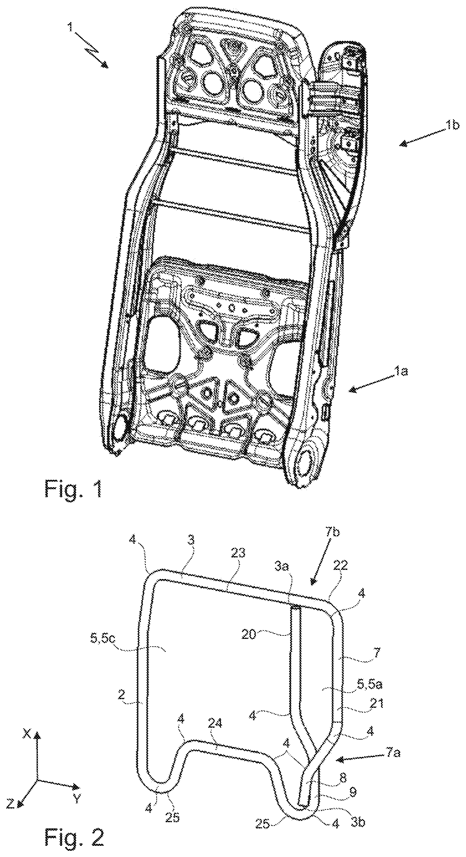
Thereby, the described method has the same advantages and embodiments, individually or in combination as in connection with the above-described backrest element and/or vehicle seat. Further advantages, objectives and features of the present invention will be explained with reference to the following description of the accompanying figures. Similar components may have the same reference signs in the various embodiments. The figures show: In The backrest element 1 and the frame element 2 extend along a longitudinal axis X, along a width axis Y and along a height axis Z. As can be seen from the figures, the frame elements 2 comprise a plurality of bends 4. These bends 4 are only exemplarily marked with the corresponding reference sign, i.e. not all bends 4 are marked with a reference sign. The backrest element 1 comprises a lower region 1 a suitable and intended to provide support in the lumbar region of the occupant, and an upper region 1 The embodiments of the frame element 2 shown in the figures all comprise a belt section 7, which is intended and suitable for arranging a belt device thereon. The belt section 7 is provided in the upper region 1 The belt section 7 has an upper portion 7 The belt section 7 is further formed in such a way that it bounds a first inner surface 5, 5 According to a first embodiment shown in Furthermore, the frame element 2 comprises a belt section 7 as described above. In this embodiment, the inner section 20 of tubular element 3 opens into the first end 3 Along the longitudinal axis X opposite the third transverse section 23 is a fourth transverse section 24 of the tubular element 3, which has a straight central section along the width axis Y, each of which laterally merges into a substantially U-shaped bend 25. A first U-shaped bend 25 merges into the first section 8. A second U-shaped bend 25 is connected to the third transverse section 23 via a lateral section 26. By means of the two U-shaped bends 25, the frame element 2 can be arranged or fastened to the lower backrest element portion 11. The third transverse section 23, the fourth transverse section 24, the lateral section 26 and the belt section 7 enclose a third inner surface 5, 5 According to the embodiment shown in Also in this embodiment, the first 8 and the second section 9 are adjacent to each other along the height axis Z. Further, according to this embodiment, the frame element 2 comprises a third transverse section 23 extending straight along the width axis Y. However, in contrast to the first embodiment, here the second transverse section 22 is not part of the third transverse section 23. Rather, the third transverse section 23 is arranged along the longitudinal axis X above the second transverse section 22 and abuts against the latter. Advantageously, the two transverse sections 22, 23 are welded together. The third transverse section 23 opens into the first end 3 A lower portion 2 The respective loop-like segment 12 comprises by a third section 14 of the tubular element 3 extending downwardly along the longitudinal axis X and a fourth section 15 of the tubular element 3 extending upwardly along the longitudinal axis X. The respective third section 14 is connected to the respective fourth section 15 via a bent fifth section 16 of the tubular element 3. In a lower portion 12 One of the two third sections 14 merges into the first section 8 along the longitudinal axis X. The second section 9 thus extends along the longitudinal axis X further along the third section 14 until it opens into the second end 3 Furthermore, a first transverse section 17 of the tubular element 3 is provided, which extends along the width axis Y between the upper portions 12 The first transverse section 17, the third transverse section 23, the lateral section 26 and the belt section 7 thus enclose a third inner surface 5, 5 In In In frame element 2, the critical point 28 at which maximum deformation and force occur is reinforced by three superimposed sections in the form of the first section 8, the second section 9 and the fourth section 15. Accordingly, the frame element 2 has an extremely stable configuration. The backrest element 1 can be provided by means of a method for manufacturing a backrest element 1 for a vehicle seat 100. The method comprises the following steps:
In In step a), the bends 4 C1 to C9 are advantageously produced first. Then a 180° rotation takes place by means of a first robot. Then the remaining bends 4 C15 to C10, but not the bend 4 C13, are generated. The preform 29 is now removed from the tube bending machine by a second robot, which preferably comprises two grippers. Now the bend 4 C13 is bent by means of the tube bending machine. The rod-like auxiliary tool 30 is then applied. See Advantageously, the method further comprises at least one of the following steps:
The tubular element 3 advantageously has a diameter in a range between 10 and 40 mm, more preferably in a range between 15 mm and 25 mm, more preferably 20 mm. The wall thickness is preferably in a range between 0.5 mm to 3 mm, more preferably in a range between 1 mm and 2.5 mm, more preferably at 1.5 mm. The applicant reserves the right to claim all features disclosed in the application documents as essential to the invention, provided that they are individually or in combination new compared to the prior art. It is further pointed out that the individual figures also describe features which may be advantageous in themselves. The person skilled in the art recognizes immediately that a certain feature described in a figure can also be advantageous without adopting further features from this figure. Furthermore, the skilled person recognizes that advantages can also result from a combination of several features shown in individual figures or in different figures. The invention relates to a backrest element for a vehicle seat, the backrest element comprising at least one frame element formed by a tubular element and forming at least one section of the backrest element, wherein a contour of the at least one frame element is given by a plurality of bends of the tubular element and is formed such that at least one inner surface is enclosed by the tubular element. 1. A backrest element—for a vehicle seat,
wherein the backrest element comprises at least one frame element which is formed by a tubular element and shapes at least one section of the backrest element, a contour of the at least one frame element being given by a plurality of bends of the tubular element and being designed in such a way that at least one inner surface is enclosed by the tubular element. 2. The backrest element according to wherein the backrest element comprising a lower region suitable and intended for providing support in the lumbar region of the occupant, the backrest element comprising an upper region suitable and intended for providing support in the shoulder region of the occupant and/or for receiving or providing a headrest. 3. The backrest element according to wherein the frame element is formed by a one-piece tubular element. 4. The backrest element according to wherein the frame element comprises a belt section intended and suitable for arranging a belt device thereon, the belt section being provided in the upper region of the backrest element, wherein at a lower end of the belt section, along a longitudinal axis X, two portions of the tubular element are abutted substantially along a height axis X. 5. The backrest element according to wherein the belt section is formed in such a way that it delimits a first inner surface, wherein a first plate-like element being arranged in this first inner surface, at least in sections, the first plate-like element being arranged on the belt section by means of a material connection. 6. The backrest element according to wherein the upper region of the backrest element comprises the at least one frame element, wherein only one frame element is provided in the upper region of the backrest element, wherein the frame element is arranged on a lower backrest element portion forming the lower region of the backrest element. 7. The backrest element according to wherein the lower region of the backrest element and the upper region of the backrest element comprise the at least one frame element, wherein only one frame element is provided. 8. The backrest element according to wherein a lower portion of frame element comprises two loop-like segments spaced from each other along a width axis Y, at which the loop-like segments each enclosing a second inner surface wherein a second plate-like element is arranged in or on each of the second inner surfaces, at least in sections, wherein the respective second plate-like element is arranged on the respective loop-like segment by means of a material connection. 9. The backrest element according to wherein the respective loop-like segment comprises a third section of the tubular element extending downwardly along the longitudinal axis X and a fourth section of the tubular element extending upwardly along the longitudinal axis X, the third section being connected to the fourth section via a bent fifth section of the tubular element, wherein in a lower portion of the loop-like segment, the third portion and the fourth portion are spaced apart along the height axis Z, wherein in an upper portion of the loop-like segment, the third portion and the fourth portion are adjacent to each other, wherein a first transverse section of the tubular element is provided extending along the width axis Y between the upper portions of the two loop-like segments. 10. The backrest element according to wherein at least one further plate-like element and/or a support strut is arranged on the frame element, the further plate-like element and/or the support strut being arranged on the frame element by means of a material connection. 11. A vehicle seat with a backrest element according to 12. A method of manufacturing a backrest element for a vehicle seat,
comprising the following steps:
a) Providing a tubular element; b) Bending the tubular element a plurality of times by means of a first tube bending machine, thereby creating a preform; c) Applying a rod-like auxiliary tool; d) Bending the preform tube about the rod-like auxiliary tool such that a lower end of the preform is brought to a middle section of the preform.CROSS REFERENCE TO RELATED APPLICATION
FIELD
BACKGROUND
SUMMARY
BRIEF DESCRIPTION OF THE DRAWINGS
DETAILED DESCRIPTION
LIST OF REFERENCE SIGNS