Stromversorgungssteuerungsschaltung für einen verkaufsautomaten
EUROPEAN PATENT AND TRADEMARK ATrORNEY A-1130 VIENNA • HIETZINGER main street 4 INTERNATIONALLY CURRENCY TECHNOLOGIES CORPORATION Taipei town center, Taiwan, R.O.C. (Powerplant) 01278 the available invention refers to a current supply control circuit for use in a vending machine and in particular to such a current supply control circuit, which shifts the note assumption mechanism of the vending machine into a currentsaving Standby mode, if the note assumption mechanism does not receive a note.
At public places most diverse kinds can be set up by vending machines, in order to spend sweet goods, ticket, change etc., if a coin or a note is thrown in. A large vending machine covers a note assumption mechanism and a number of sales master units. Conventional vending machines are frequently in such a way laid out that they are operated directly with city stream. As soon as once installs, the note assumption mechanism is kept constant in switched on condition. Since the note assumption mechanism is switched on constantly, much electricity is used, even if the vending machine is in the no-load operation.
It would be desirable to create a current supply control circuit for a vending machine which overcomes the disadvantages mentioned.
TEL.: (+43 1) 879 17 06. FAX: (+43 1) 879 17 07. Email: MAIL@PATENTE.NET • WEB: WWW.PATENTE.NET FIRST BANK: 038-56704. BLZ: 20111 • IBAN: AT102011100003856704 • BIC: GIBAATWW • VAT: RK U 53832900 • v “” °°°°°°' • ' °o o. • gg • • oo oo • • • the available invention was made under the regarded circumstances. It is the principal purpose of the available invention to create a current supply control circuit for use in a vending machine which shifts the note assumption mechanism automatically from the operating mode into the Standby mode, if the vending machine does not receive a note, and/or of the Standby mode into the operating mode, if the vending machine receives a note. In accordance with an execution form of the available invention the current supply control circuit covers an impulse signal generator, which are in the note inlet of the note assumption mechanism of the vending machine installed and for it appropriate, would bring in with to a note into the note inlet of the note assumption mechanism a trigger signal to produce, furthermore a driver and a trigger unit, which steer the driver, in order to switch the note assumption mechanism as a function of the presence of the impulse signal from the impulse signal generator between the currentsaving Standby mode and the operating mode. In accordance with an alternative form of the available invention the current supply control circuit covers a trigger unit, which is appropriate to produce a trigger signal to receive and a driver, which is appropriate for it, the trigger signal from the trigger unit to. The driver connects the current supply with the note assumption mechanism, if it receives the trigger signal from the trigger unit, or separates the current supply from the Banknotenannaho ol oooo oooo o oooo to QD O0 O0 • meeinrichtung, if it does not receive a signal from the trigger unit.
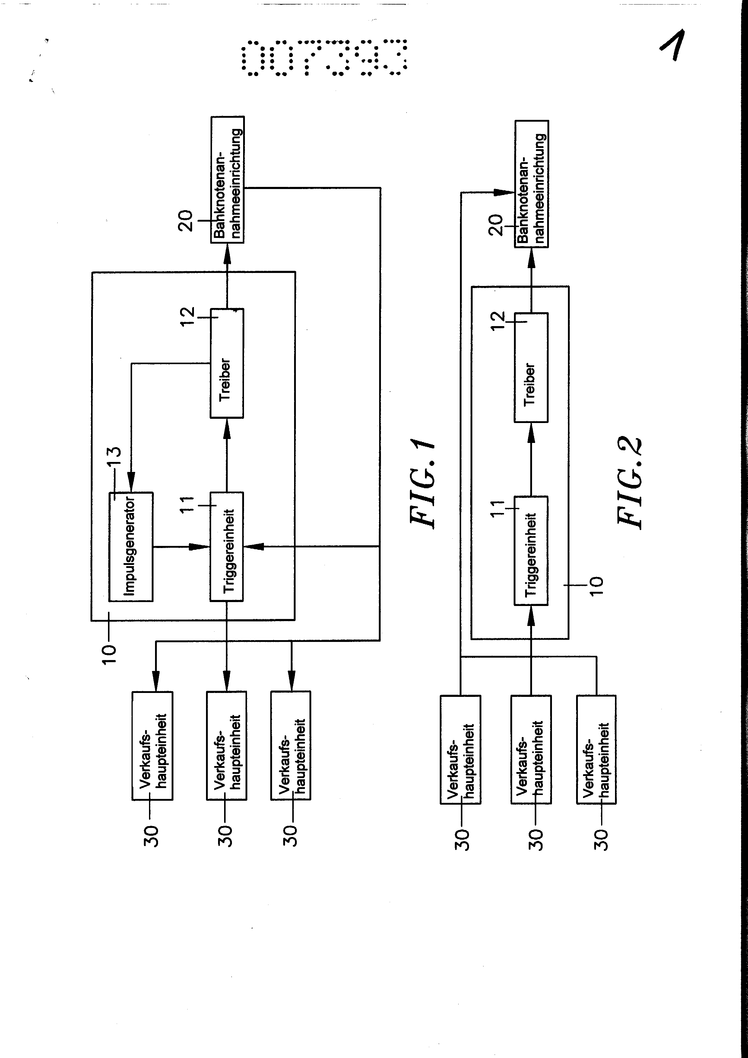
Short description of the designs Fig. 1 is a block diagram, which shows the system configuration in the first trigger mode in accordance with the available invention.
Fig. 2 is a block diagram, which shows the system configuration in the second trigger mode in accordance with the available invention.
Fig. 3 is a block diagram of the current supply control circuit in accordance with the available invention.
Fig. 4 is a flow chart of the available invention, if it is taken in enterprise (I).
Fig. 4A is a flow chart of the available invention, if she is taken in enterprise (II).
Fig. 5 is a Standby mode flow chart in accordance with the available invention.
Fig. 6 is a note rejecting mode flow chart in accordance with the available invention.
With reference to the Fig. a current supply control circuit 10, which is developed in accordance with the first trigger mode of the available invention, installed and electrically between the note assumption mechanism 20 is and the sales master units 30 of the vending machine switched for 1 and 3 in a vending machine and covers an impulse signal generator 13, a trigger unit II and a driver 12. The tons oo oooo eooo oQ oooo • • • • °De Qe° °oge oo Oe impulse signal generator 13 is installed in the inlet of the note assumption mechanism 20. The exit pin OUT of the trigger unit II is attached to the sales master unit 30.
After a given time interval, in which the Einla5 of the note assumption mechanism 20 did not receive a note, the note assumption mechanism 20 triggers a flip-flop (UI) iii of the D-type, in order pin 6 of, high, up, low " - potential to draw, whereby pin 5 to zero is set. At this time a n-channel field-effect transistor (Q2) is arranged 121 of the driver 12 to it to switch a p-channel field-effect transistor off (Q3) 122 which prevents the main power supply to arrive far at the note assumption mechanism 20 and from there crosses the note assumption mechanism 20 directly into the currentsaving Standby mode and spends an enabling signal EN by the n-channel field-effect transistor (QI) 112 of the trigger unit ii, in order the exit pin OUT ùhigh " - potential to hold, which informs the sales master units 30 over the StandbyModus condition of the note assumption mechanism 20. If the Standby mode is reached, an oscillation module 131 of the impulse signal generator 13 propels elne LED (light emitting diode) 132 to hold in order to emit light, which will then receive from a Phototransistor 133, in order Vpt ùlow " - potential in wait position for the operating mode.
If a note is introduced to the inlet of the note assumption mechanism 20, it blocks itself the light the LED 132, which causes, da5 the RC element (Widerstand6 ....... oot oOQo oooö ö. .OOo.O ° • condenser) up-loaded, in order to change Vpt of, low " - potential up, high - potential and to trigger thus pin 1 of the D-type-Flip-flop (Ul) III and to change the status of pin 5 of the D-type-flip-flop (UI) III of ùlow " - potential on ùhigh " - potential. If itself pin 5 of the D-type-Flip-flop (UI) III on ùhigh - lotential it changes the n-channel field-effect transistor (Q2) is headed for 121, in order to switch the p-channel field-effect transistor (Q3) for 122 on, which makes it possible that the main power supply arrives at the note assumption mechanism 20. At this time the trigger unit II spends an enabling signal, in order to head for the n-channel field-effect transistor (QI) 112, whereby pin OUT of, high " - up, low " - changes for potential. As soon as itself pin OUT on ùlow " - potential changed, the trigger unit gives a signal to the sales master units 30, which informs the sales master units 30 over the operating mode condition of the note assumption mechanism 20 to II.
Fig. 2 is a block diagram of the second trigger mode in accordance with the available invention. The current supply control circuit 10 is switched electrical between a note assumption mechanism 20 and several sales master units 30 and covers a trigger unit ii and a driver 12.
With repeated reference to the Fig. 2 and 3 becomes, if the sales master units 30 are not released (i.e. the respective pushbuttons are switched off), the note assumption mechanism 20 of the operating mode into the Stand8 o, po eooe oe o oo ooo by-mode put back. The expiration of putting back of the operating mode into the Standby mode is below described.
The diode D detects the potential level of pin OUT. If, high " - potential is detected by pin OUT, pin 6 of the D-type-Flip-flop (UI) becomes Iii of the trigger unit II with the help of one, low " - potential triggered, which causes that pin of the D-type-Flip-flop (Ul) changes for iii of the trigger unit ii of ùhigh " - potential up, low " - potential. The ùlow " - potential signal then by pin 5 of the D-type-Flip-flop (Ul) iii of the trigger unit ii by the n-channel field-effect transistor (Q2) 121 to the p-channel field-effect transistor (Q3) 122 is led, whereby the p-channel field-effect transistor (Q3) prevents 122 the main power supply to arrive at the note assumption mechanism 20 and thus enters the note assumption mechanism 20 the currentsaving Standby mode.
If a sales master unit becomes released 30 (switching on), an impulse over pin OUT is sent, in order to trigger pin 1 of the D-type-Flip-flop (UI) iii of the trigger unit ii, whereby pin 5 of the D-type-Flip-flop (Ul) changes for Iii of the trigger unit ii of, low " - potential on ùhigh - potential, which, high - potential over the n-channel field-effect transistor (Q2) is then sent 121 of the driver 12 to the p-channel field-effect transistor (Q3) 122, which caused that the p-channel field-effect transistor (Q3) is switched on 122, around the main power supply for note assumption mechanism i i ":: “:
to pass, and by it the note assumption mechanism 20 steps into the operating mode more ber.
The Fig. 4 and 4A shows the Betriebsabl ufe of the available invention. If the note assumption mechanism is started, it runs off in accordance with the following steps:
One switches on for 401 current supply; 402 system initialisation; It determines 403 whether the system works normally or turns into not, and to the step 404 if, or to the step 409, if no; It determines 404 whether the note assumption mechanism is clogged or goes not, and then to the step 405, if clogs, or to the step 407, if does not clog; 405 send work message at main sales unit and go then to step 406; To 406 go into disturbance recovery mode over (see Fig. 6); 407 send work message at main sales unit and go then to step 408; To 408 go into Standby mode over (see Fig. 5); 409 determine, whether main sales unit is attached, and go then to step 412, if attached, or step 410, if not attached; It determines 410 whether from the Standby mode into the operating mode is to be changed or not, and go to step 412, if, or step 411, if no; “OO o • 411 preparing for the Standby mode, goes then to step 409; 412 control room on would bring in a note, goes then to the step 413; 413 determine, whether any note which can be accepted is present, and go to step 415 if, or step 414, if no; To 414 preparing for the entering the currentsaving Standby mode, go then to the step 413; 415 accept the imported note and go then to the step 416; 416 determine, whether the imported note was brought in position, and go then to the step 418 from $2, if, or step 417, if no; To 417 go into the note rejecting mode over (Fig. 6); 418 determine, whether sales master unit is attached, and go to the step 419 if, or step 425, if no; 419 determine, whether the sales master unit one permitted, the note accept or not, and go to the step 420 if, or 428, if no; 420 inform the sales master unit about the value of the note and go then to the step 421; 421 determine, whether the sales master unit was informed of it, wait for a transaction and go to the step 422 if, or step 426 of S3; e)…. ÖoosöOOOOOeOÖ O0 • ù. (-”.:
oo oo 422 determine, whether the sales master unit was informed of it, a note accept or not, and go to the step 423 if, or step 428, if no; 423 send the note to the funds container and go then to the step 424; 424 inform the sales master unit about the conclusion of the note assumption procedure and go then to the step 412 from SI; 425 determine, whether the waiting period ran off, and go to the step 428 if, or to the step 418, if no; It determines 426 whether for the connection of sales sale is to be waited or not, and go then to the step 421 from S4, if, or to the step 427, if no; 427 intend, whether the communication time ran off, and go then to the step 428, if it ran off, or for the step 421 of $4, if not; To 428 go into the note rejecting mode (see Fig. 6) over.
Fig. 5 describes the expiration of the Standby mode. If the note assumption mechanism changes into the Standby mode, it runs off after the following steps:
501 beginning Standby mode; It determines 502 whether the sales master unit sent a release instruction or not, and goes to the step 503 if, or to the step 505, if no; QO g • • • • oQ 00,503 determines, whether the sales master unit terminated communication, and goes to the step 504 if, or to the step 507, if no; 504 determine, whether communication ended, and go to the step 506 if, or to the step 507, if no; 505 determine, whether the note assumption mechanism is in the StandbyModus, and go to the step 506 if, or to the step 504, if no; 506 change into the Standby mode; 507 leave the Standby mode.
It becomes on Fig. 4 referred, which shows the flow chart of the available invention, if the note assumption mechanism were started, and Fig. 6, which shows the flow chart of the note rejecting mode. If into the note rejecting mode one changes, this runs off in accordance with the following steps:
601 beginning note rejecting mode; 602 determine, whether the note was rejected, and go then to the step 412 from Sl, if, or to the step 603, if no; 603 eliminate the note blockage problem and go then to the step 604; 604 determine, whether the note clogs further, and go to the step 605 if, or to the step 606, if no; 605 preparing for the entering the Standby mode; OO OO: °. .o-o: --: o--°o':
. : : °o oo 606 it determines 0 • ° • ° Qo whether the note blockage problem can be eliminated or not, and goes to the step 605 if the note blockage problem cannot be eliminated or to the step 607, if the note blockage problem can be eliminated; 607 eliminate the note blockage problem; 608 determine, whether the note rejection is finished, and go then to the step 412 from SI, if, or to the step 606, if no.
As indicated the note assumption mechanism 20, if it or a sales master unit 30 produced a trigger signal, returns above directly from the Standby mode to the operating mode. In the no-load operation the current supply control circuit i0 separates the current supply from the note assumption mechanism 20, which holds the note assumption mechanism 20 in the currentsaving Standby mode.
A prototype of the current supply control circuit for use in a vending machine became with the characteristics of on designs of the Fig. 1-6 developed. The current supply control circuit for the vending machine works smoothly and offers all discussed characteristics and advantages.
Even if special execution forms of the invention were in more detail described for illustration, numerous modifications and extensions know made who \ _. 1 6 - • • • • • B EO • ee oo oe oo that, without the spirit and the framework of the invention, as it in the closed requirements defined is to be left.
0o o eoeo o o oo oooo • “ioo gg • oo 1 In a vending machine which has a bill acceptor for accepting banknotes, the bill acceptor is disconnected from the power supply, along with other main units of the vending machine, until a triggering signal is received indicating the presence of a note in the acceptor inlet. The trigger comprises an optical sensor, light from a pulse-driven LED being blocked to cause a circuit to be energised to end the power-saving stand-by mode. i. Current supply control circuit for a vending machine with a note assumption mechanism and at least a sales master unit, comprehensively an impulse signal generator, a trigger unit and a driver, whereby the impulse signal generator is in the Banknoteneinla5 of the note assumption mechanism installed and for it trained would bring in to produce with a note into the note inlet of the note assumption mechanism a trigger signal; whereby the trigger unit mentioned steers the driver, in order to set or from this to separate the current supply as a function of the presence of the impulse signal from the impulse signal generator on the note assumption mechanism; and whereby the driver is trained to steer the trigger signal received from the trigger unit to and the enterprise of the note assumption mechanism as a function of the presence of the trigger signal from the trigger unit. 2. Current supply control circuit according to requirement i, with which the trigger unit a n-channel field-effect transistor (QI), a flip-flop of the D-type, whose pin OUT is parallel with the n-channel field-effect transistor (QI) attached to the impulse signal generator, and a D-type-Flip-flop exhibits, which are attached to the driver.
oo Qo oo IP o “o oo oeoo oo oo oe oo 3. Current supply control circuit according to requirement 2, with which the impulse signal generator covers an RC element (resistance condenser), a Phototransistor, an oscillation module and a light emitting diode. 4. Current supply control circuit according to requirement 2, with which the driver exhibits a n-channel field-effect transistor (Q2) and a p-channel field-effect transistor (Q3), which is attached at the D-type-Flip-flop the trigger unit electrically, whereby the p-channel field-effect transistor (Q3) is appropriate for it, the current supply to the note assumption mechanism to put on.
Current supply control circuit for use in a vending machine with a note assumption mechanism and at least a sales master unit, comprehensively a trigger unit and a driver, whereby the trigger unit is appropriate to produce a trigger signal for the controlling of the enterprise of the driver; whereby the driver is appropriate to set the trigger signal received from the trigger unit to and the current supply on the note assumption mechanism if the trigger unit produces the trigger signal to separate or the current supply from the note assumption mechanism to if the trigger unit does not produce the trigger signal any longer. 6. Current supply control circuit according to requirement 5, with which the trigger unit a D-type-Flip-flop exhibits, which is attached to the driver.
oo oo OQOQ O OQ QOQO • Q • Q OO QQ OQ 7. Current supply control circuit according to requirement 5, with which the driver exhibits a n-channel field-effect transistor (Q2) and a p-channel field-effect transistor (Q3), which are attached at the D-type-Flip-flop the trigger unit electrically, whereby the p-channel field-effect transistor (Q3) is appropriate for it, the current supply to the note assumption mechanism to put on.