Rührwerk für Flüssigkeiten, insbesondere für Gülle
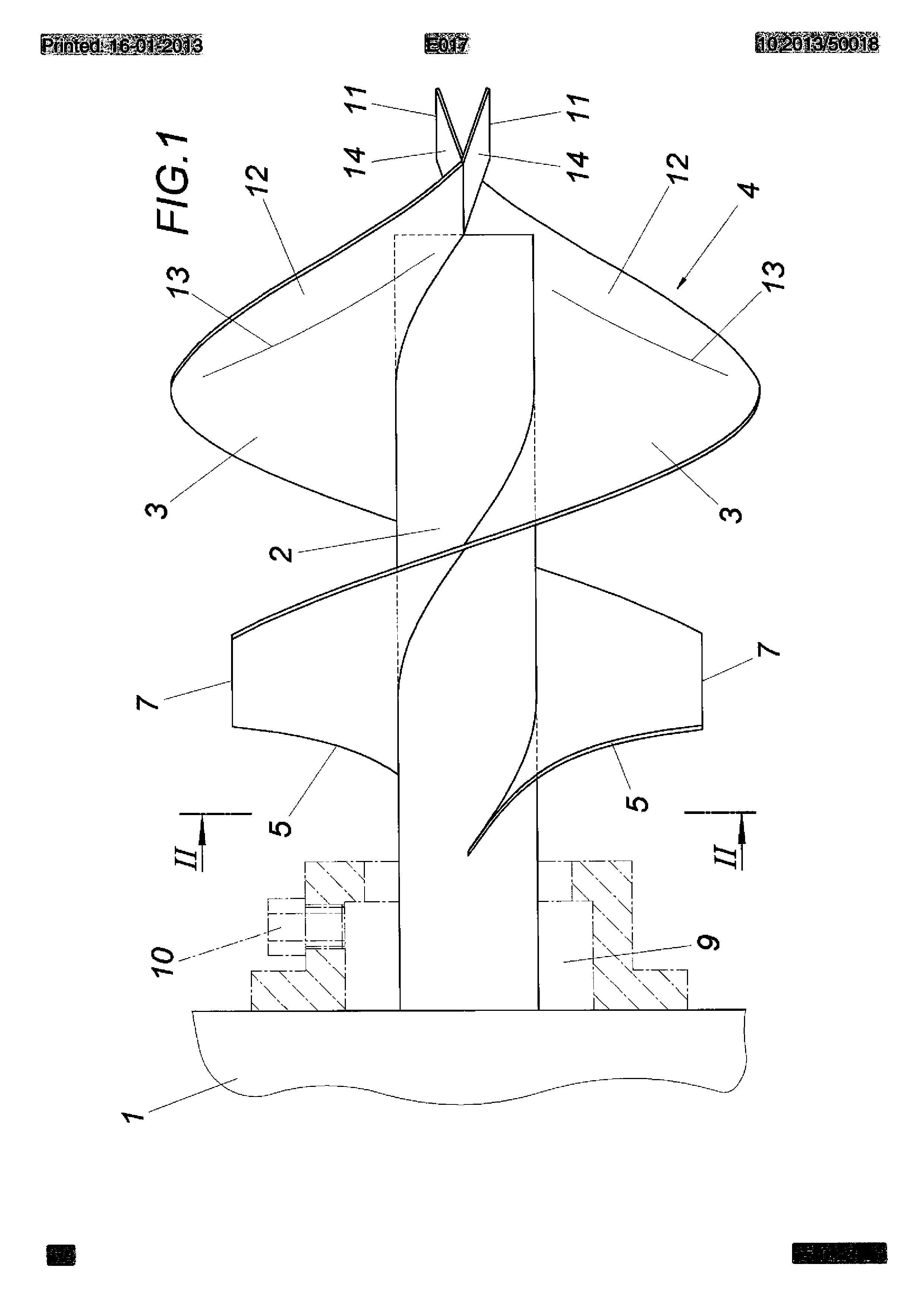
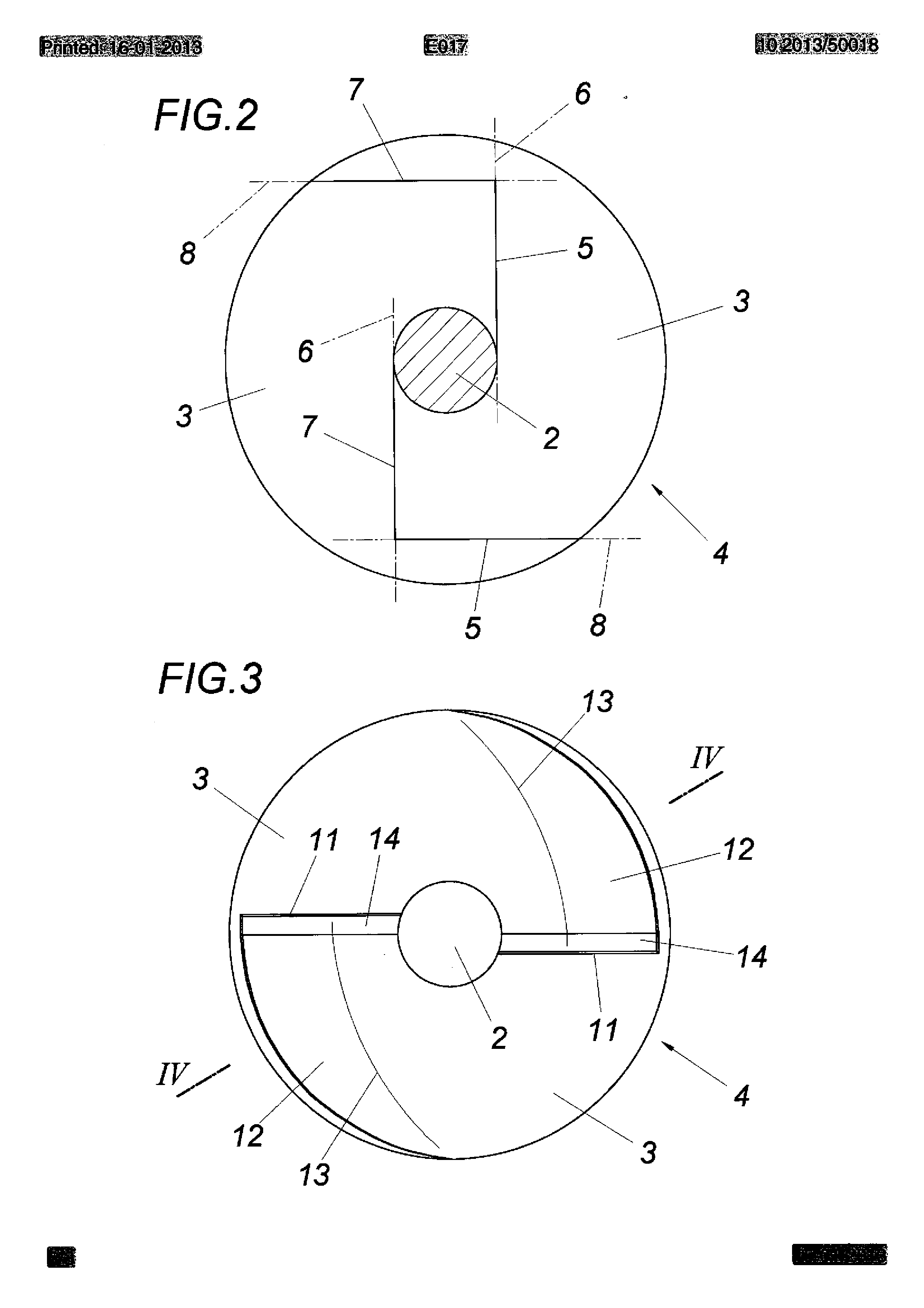
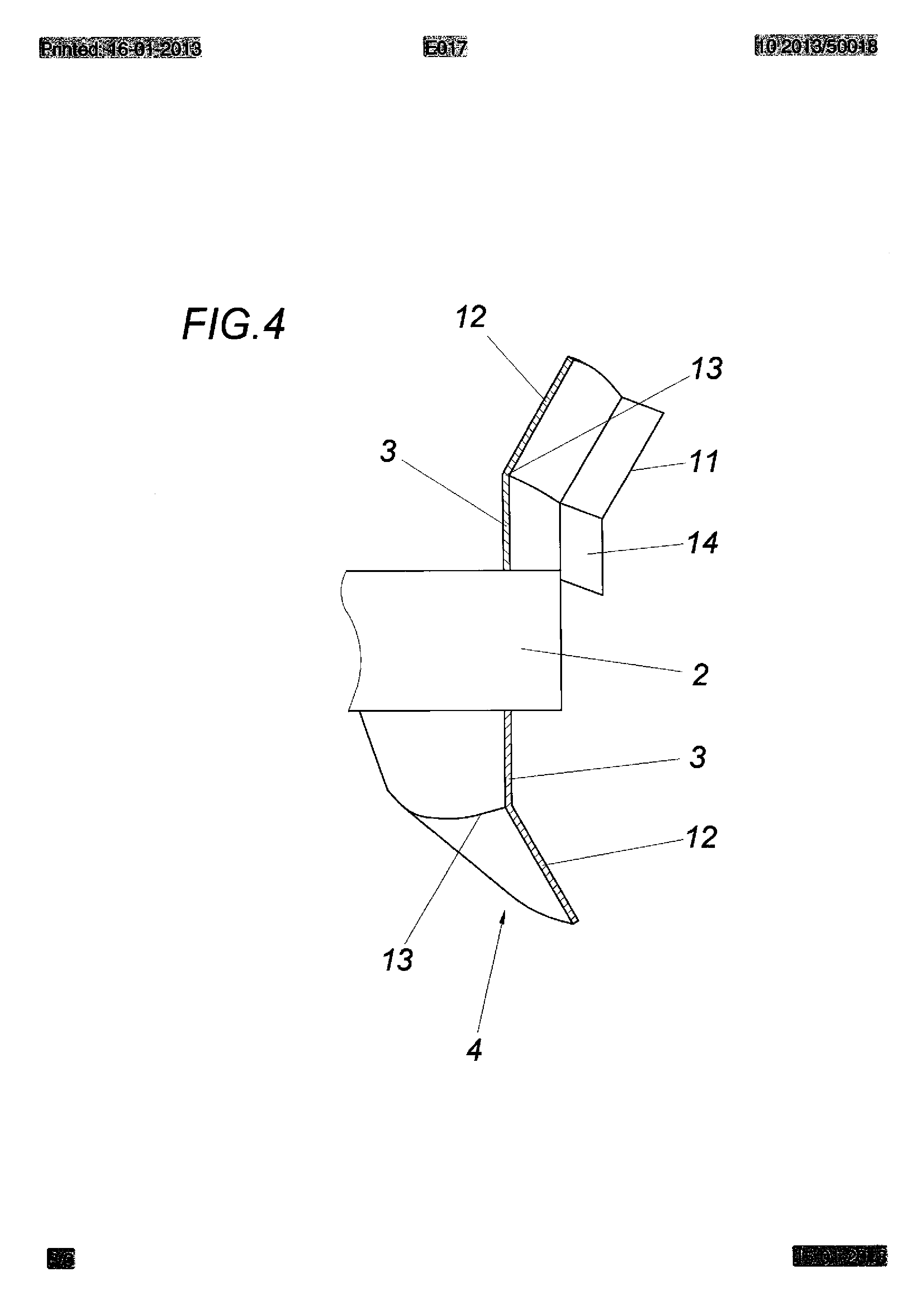
The invention refers to agitator for liquids, in particular for liquid manure, with a propelled, guidanceringless propeller, which exhibits at least a propeller blade with Saugund of a printing edge, running helically along a propeller shaft. In order to improve agitators in such a way for air entry in liquid manure that implemented the dependence of the air sucking in on an air gap between one of the propeller shaft front wall and the propeller blades one avoids, is it admits (RK 407,689 B), the propeller suction-side with to the radially running suction edges of the propeller blades following to provide a propeller-laterally resulting negative pressure area axially locking disk whereby this negative pressure area is connected with the air intake line. Into the negative pressure area, which results between the propeller blades and the disk locking axially the propeller blades, air is sucked in, which is axially discharged with again from the outside the sucked in liquid, so that within the axially discharged liquid a to a large extent even air distribution adjusts itself. The building expenditure remains however high by the additional arrangement of a disk comparatively, without improving the suction capacity crucially. In addition conditions remain unconsidered by this well-known construction, with which liquid is to be only sucked in and agitated, not be registered however at the same time air into the liquid. The invention is the basis thus the task, an agitator for liquids, in particular for liquid manure to out-arrange so that with simple constructional measures a noticeable increase of the agitating achievement can be obtained, independently of whether air is to be registered at the same time or not. On the basis of an agitator of the initially described kind the invention solves the task posed by the fact that the suction edge of the propeller blade runs at least approximate along the cut line between the spiral surface of the propeller blade and a plane of section tangential to the propeller shaft and changes then into a connecting edge, which essentially follows the cut line of the spiral surface with a surface aligned parallel to the Propellenwelle transverse to the tangential plane of section. By any longer radially the process of the suction edge of the propeller blade in a plane of section, tangential aligned to the driveshaft, to the propeller shaft in the cooperation with a following connecting edge, which essentially follows the cut line of the spiral surface of the propeller blade with to the propeller shaft parallel, but transverse to the plane of section of the suction edge a running surface, in surprising way good suction conditions are not guaranteed, which provide for a increased mechanical handling capacity of the sucked in liquid, independently of whether liquid is to be only rolled over or be registered into the rolled over liquid air. If air is registered at the same time into the liquid, then favourable conditions for a good mixture of sucked in air with the liquid flowing in into the propeller result. In particular when agitating liquid manure favorable suction conditions can be reached both for the liquid for itself and if necessary for air sucked in at the same time, if the suction edge and the following connecting edge exhibit the same length to the screw-shaped running outer edge of the propeller blade approximately. For the increase of the mechanical handling capacity and the arranged output the propeller blade to an extent extent ending with the printing edge can exhibit an edge section bent out from the spiral surface in the direction of rotation of the propeller, if additionally opposite the spiral surface and the bent out Randabschnitΐ a final bar of the propeller blade bent in the sense of an enlargement of the upward gradient forms the printing edge. The current seized by the propeller is additionally accelerated by the edge section bent out to a divert-lateral extent extent of the propeller in direction of rotation from the spiral surface of the propeller blade, whereby with the printing pressure of the propeller blade forming, according to bent final bar additionally pressure on the liquid flow leaking out into the liquid one expenditure-practices. From there a favourable agitator with a good efficiency can be made available by the sum of these measures. With the described output conditions on the print page of the propeller blade the flow conditions within the range of a liquid manure container in favourable kind can be considered, if the edge section bent out from the spiral surface extends along an extent range of approximate 90°. The throughput of the agitator depends on the number of used propeller blades. Although with only one propeller blade quite responding agitator achievements can be furnished, particularly favourable throughput conditions result, if the propeller exhibits two propeller blades phaseshifted by 180°, because this case the construction expenditure remains still limited. In the design the invention article is for example represented. Fig show. 1 a propeller of an agitator according to invention for liquids, in particular for liquid manure, in a schematic side view, Fig. 2 a cut after the line ll-ll the Fig. 1 in a smaller yardstick, Fig. 3 a front side opinion of the propeller in a smaller yardstick and Fig. 4 a cut after the line IV-IV of the Fig. 3 in a larger yardstick. The represented agitator, which is used for example in a liquid manure container, exhibits a propeller shaft 2 propelled by a dipping engine 1, which phaseshifts two by 1 80° arranged propeller blades 3 carries, which extend in form of a spiral with a full turn along the propeller shaft 2. The drive of the propeller shaft 2 must however under no circumstances via a dipping engine take place and can for example over a power-takeoff be made. So that for the propeller formed by the two propeller blades 3 4 favourable suction conditions result, the suction edge 5 the propeller blade 3 runs not in conventional way in radial direction, but in a plane of section 6, which runs tangential to the propeller shaft 2, like this the Fig. 2 to be taken can do. In the remark example this plane of section 6 is an even surface, which creates simple manufacture conditions for the suction edge 5, because the propeller blades 3 along this even plane of section 6 are to be only besäumen. From the Fig. 1 and 2 is to be taken that the suction edges 5 do not run up to the outer edge of the propeller blades 3. The suction edges 5 change rather into connecting edges 7, those essentially the cut line of the spiral surface of the propeller blades 3 with to the propeller shaft 2 parallel, but transverse to the tangential plane of section 6 follow aligned surface 8 (Fig. 2), which is again favourably even. The arrangement is so met with the fact that the length of the suction edges corresponds at least approximated to the length of the connecting edges 7. With such a training of the flowing in side of the propeller 4 favourable Ansaugbedi∩gungen can be created, not only for the liquid, into which the agitator is inserted, but also for the case that into the liquid air be registered is with simple constructional means. For this purpose suction face of the propeller 4 an annular space 9 interspersed by the propeller shaft 2 can to be planned, like this in the Fig on that the dipping engine 1 course-turned. 1 is dash-dotted suggested. Since this annular space 9 over a connection 10 is attached to an air intake line, over the propeller blades 3 from the annular space 5 air is sucked in, which flows in axial direction into the propeller 4 and mixes with the likewise sucked in liquid during flowing through the propeller 4 intimately. The liquid flow enriched promoted in axial direction by the propeller 4 with the help of the propeller blades 3, if necessary with air can be accelerated on the Ausströmseiΐe of the propeller 4 additionally. For this the propeller blades 3 to a 1 extent extent of essentially 90°, locked with a printing edge 1, form an edge section 12, which is bent out from the spiral surface of the respective propeller blade 3 in the direction of rotation of the propeller 4, like this in particular the Fig. 3 and 4 to recognize leaves. The bending range is suggested thereby by a line 13. The acceleration of the leaking out flow direction attainable with this bending is strengthened additionally by a bent final bar 14, which forms the Druckka∩te 11 and in the sense of an enlargement of the upward gradient in relation to the spiral surface of the propeller blades 3 bent runs. The output of the liquid and/or the liquid air mixture from the agitator is accordingly supported by these leak out-lateral measures and thus the agitating effect within the container taking up the agitator. Patent lawyers Dipl. - engineer Helmut of pretty Dipl. - engineer Karl Winfried lightme Spittelwiese 7, A 4020 Linz (38991) II The machine has a driven propeller (4) including a propeller blade (3) helically extending along a propeller shaft (2) and having a suction edge (5) and a pressure edge (11). The suction edge of the propeller blade approximately runs along an intersection between a tooth surface of the propeller blade and a tangential sectional area of the propeller shaft, and passes over a connecting edge, where the intersection of the tooth surface and the tangential cross-sectional area follows a facing surface. 1. Agitator for liquids, in particular for liquid manure, with a propelled, guidanceringless propeller (4), that at least one along a propeller shaft (2) helically running propeller blade (3) with Saugund of a printing edge (5, 1 1) it exhibits, in the fact characterized that the suction edge (5) of the propeller blade (3) at least approximate along the cut line between the spiral surface of the propeller blade (3) and one to the propeller shaft (2) tangential plane of section (6) and then into a connecting edge (7), those runs essentially turns into the cut line of the spiral surface with one to the propeller shaft (2) parallel, transverse to the tangential plane of section (6) aligned surface (8) follows. 2. Agitator after requirement 1, by the fact characterized that the suction edge (5) and the connecting edge exhibit (7) approximated the same length. 3. Agitator according to requirement 1 or 2, by the fact characterized that the propeller blade (3) in one with the printing edge (1 1) ending extent range one from the spiral surface in the direction of rotation of the propeller (4) bent out edge section and the fact that in relation to the spiral surface and the bent out edge section (1 2) in the sense of an enlargement of the upward gradient bent final bar (14) of the propeller blade (3) the printing edge (11) exhibit (12) forms. 4. Agitator according to requirement 3, by the fact characterized that the edge section (12), bent out from the spiral surface, extends along an extent range of approximate 90°. Agitator after one of the requirements 1 to 4, by the fact characterized that the propeller (4) two around 180° propeller blade (3) phaseshifted exhibits. Linz, on 15 January 2012 Gottfried Gritzner through: /DI Helmut Hübscher/(electronically marked)