CENTRIFUGE FOR THE WET MECHANICAL SEPARATION OF SOLID MIXTURES
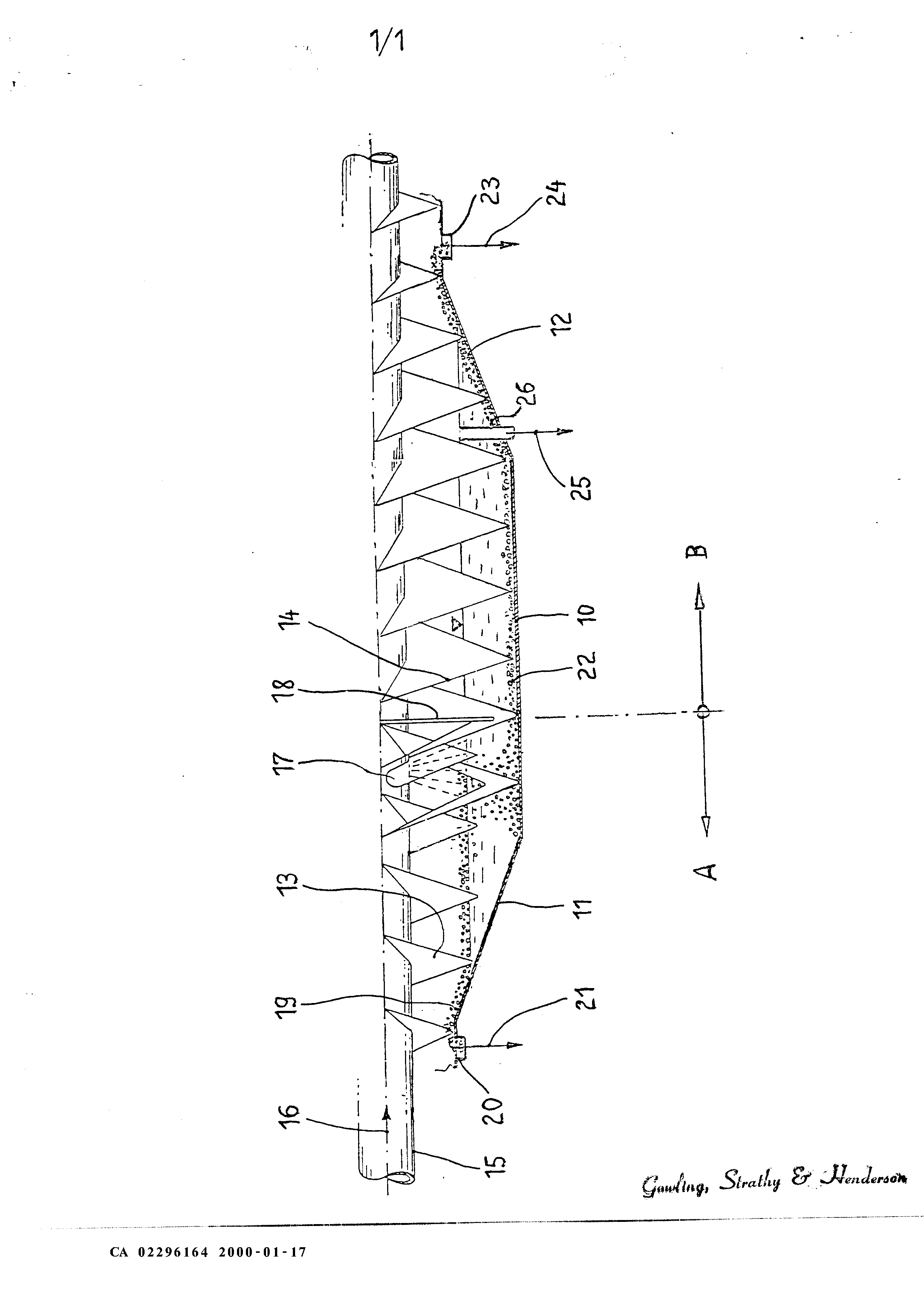
The present invention is based on the objective of developing a centrifuge that is not only able to classify fine-grained materials with certain grain spectrums in very small increments, but is also suitable for carrying out a sorting process simultaneously with the classifying process in one and the same machine so as to allow the separation of solid impurities, in particular, from the fine grains to be obtained. According to the invention, this objective and others, are attained with a centrifuge including the characteristics disclosed in the present case and claims. The centrifuge according to the present invention represents a combination of a sorting centrifuge and a classifying centrifuge. The sorting zone of the centrifuge according to the invention extends from the immersion disk that is immersed into the suspension fluid and rotates with the conveyor screw to the floats discharge at one end of the centrifuge. The classifying zone extends diametrically opposite from the immersion disk to the other end of the centrifuge. The supplied material, namely a fine-grained, ground solid with a certain grain spectrum, e.g., calcium carbonate, which is contaminated, e.g., due to the abrasion of rubber on the transport belt, is suspended, e.g., in water and introduced into the sorting zone of the centrifuge according to the invention. The supplied suspension may have a density of, for example, 1.6 2 of 8 CA 02296164 20000117 g/cm3. In the sorting zone, the distinctly lighter impurities, e.g., rubber particles with a density of, for example, 1.3 g/cm , float to the surface and are transported to the floats discharge openings by a conveying element, e.g., the helical screw of a conveyor screw for floats. The immersion disk prevents the floating impurities from remixing with the classifying suspension. In any case, the suspension that flows into the classifying zone underneath the immersion disk is free of impurities. In the classifying zone, the solid suspension, e.g., the calcium carbonate, flows in the direction of the other centrifuge end. The coarse grain can be transported to the coarse grain discharge in the form of sinks by the helical screw of the conveyor screw for sinks, while the classified fine or finest grain remains in the suspension fluid and is discharged with the suspension as a third phase, e.g., by means of a system of overflow pipes, skimming pipes, skimming disks, etc. Alternatively, it would also be possible to discharge the coarse-grained solids in the classifying zone by means of nozzle-shaped openings in the basket shell, and to discharge the fine-grained solids with the suspension fluid at the end of the centrifuge. The present invention allows a precise grain classification as well as the separation of interfering impurities in one and the same centrifuge so that prior cleaning stages like screens or other sorting techniques can be eliminated. In this case, the sorting process, in particular, the separation of impurities, does not interfere with the precise grain classification, which simultaneously takes place in the centrifuge. BRIEF DESCRIPTION OF THE DRAWING Fig. 1 is a schematic, longitudinal, sectional view of a centrifuge as disclosed in the present case. DETAILED DESCRIPTION OF THE PREFERRED EMBODIMENTS The invention and its numerous and additional characteristics and advantages are described in greater detail below with reference to one embodiment that is schematically illustrated in Fig 1 Fig. 1 shows a longitudinal section through the rotor of the centrifuge according to the present invention that, for example, is designed in accordance with a biconical solid basket screw-type centrifuge with a cylindrical basket shell part 10 that connects at each end to a corresponding conical basket shell part 11 and 12, respectively. A rotatable conveyor screw is positioned coaxially in the rotatable centrifuge basket. This conveyor screw rotates in the centrifuge basket with a differential rotational speed and contains a helical screw 13 for floats in the left longitudinal region and a helical screw 14 for sinks that rotates in the opposite direction in 3 of 8 CA 02296164 20000117 the right longitudinal region. The supplied suspension 16, e.g., a fine-grained material, which is contaminated with rubber, plastic, etc. and suspended in water, such as kaolin, calcium carbonate, etc., and has a certain grain spectrum, is introduced through the hollow screw shaft 15. The suspension of the grain spectrum, from which at least one finest grain fraction that is free of contaminants should be obtained, is introduced into the centrifuge basket through at least one hollow shaft opening 17 into the sorting zone A, which is separated from an adjacent classifying zone B by an immersion disk 18 that rotates with the conveyor screw 15 and is immersed in the suspension. The distinctly lighter impurities contained in the supplied material float to the surface very rapidly in the sorting zone A due to the difference in density between the supplied suspension and the impurities under the influence of the centrifugal field. These floats 19 are lifted out of the suspension fluid by the conical basket shell part 11 and transported to the floats discharge openings 20 by the helical screw 13. The floats are removed from the centrifuge basket in the form of separately obtained impurities 21 at these discharge openings. Depending on its composition, the product 21 can be transported to additional processing stations. In the sorting zone A, the heavy particles of the ground material contained in the suspension, e.g., calcium carbonate with a density of approximately 2.6 g/cm3, are forced against the wall of the centrifuge basket 10. These sinks 22 flow into the classifying zone B of the centrifuge together with the suspension fluid underneath the immersion disk 18, which prevents the floats 19 from remixing with the classifying suspension. In the classifying zone B, a highly selective precise grain classification in small increments on the order of a few pm takes place in a co-current flow. During this process, the sinks 22 are transported through the classifying zone B by the helical screw 14 for sinks, which transports material in the opposite direction than the helical screw 13 for floats. The coarse grain is lifted out of the suspension fluid on the conical basket shell part 12 and transported to the sinks discharge openings 23, where coarse grain 24 with a grain size of, for example, >40 \im is discharged from the centrifuge basket by the helical screw 14. The fine grain with a grain size of, for example, <40 jwn or less, which was separated from the coarse grain in the classifying zone B, remains in the suspension and is removed from the centrifuge in the form of a third phase 25, in this case, as a highly pure and valuable finest grain product together with the suspension fluid. In the embodiment shown, this discharge is realized by means of several overflow pipes 26 that are distributed over the periphery. The radially inner openings of these overflow pipes make it possible to vary and maintain a constant level of the separating fluid in the centrifuge basket. This fine grain discharge 25, 26 is arranged approximately at the transition from the cylindrical basket shell part 10 to the conical basket shell part 12 for the discharge of sinks in the embodiment shown. The classifying effect for the 4 of 8 CA 02296164 20000117 respective grain spectrum to be classified can be influenced, if necessary, by designing the helical screw 14 for sinks in the conical basket shell 12 with a different pitch than in the cylindrical basket shell part 10. In an alternative embodiment, the pipes 26 are realized in the form of nozzle-shaped discharge openings for discharging the coarse-grained solid which are arranged in the basket shell, where the fine-grained solid is discharged together with the suspension fluid at the discharge openings 23 in this case. In order to maintain a high efficiency of the classifying zone B for the highly selective precise grain classification, the cylindrical basket shell part 10 has a length that is preferably smaller than approximately 5 times the basket shell diameter, In addition, the axial length of the conical basket shell part 12 with the sinks discharge may differ from the axial length of the conical basket shell part 11 with the floats discharge. The cone angle of the conical basket shell parts 11 and 12 can be, for example, <120. In order to favorably influence the separation or removal of the fine grain/finest grain from the grain spectrum in the classifying zone B so as to achieve a highly selective classification of coarse grains, systems for mixing the suspension can be provided within the classifying zone B. The biconical solid basket screw-type centrifuge according to the present invention is not only suitable for classifying grain spectrums so as to obtain at least one grain class of a ground solid, but also for dewatering or the separation of solids and liquids in sludges that contain materials that can be separated from the sinks separately as a third phase in the form of floats. Although the present invention has been described in terms of particular embodiments and applications, one of ordinary skill in the art, in light of this teaching, can generate additional embodiments and modifications without departing from the spirit of or exceeding the scope of the claimed invention. Accordingly, it is to be understood that the drawings and descriptions herein are proffered by way of example to facilitate comprehension of the invention and should not be construed to limit the scope thereof. of 8 CA 02296164 20000117 The present invention discloses a centrifuge that is not only suitable for a highly selective classification of fine-grained solids in very small increments, but can also be used for carrying out a sorting process and a classifying process simultaneously in one and the same machine so as to separate solid impurities from the fine grain to be obtained. According to the invention, a sorting zone (A) and a classifying zone (B) are integrated into this centrifuge, wherein the sorting zone (A) extends from the immersion disk (18) to the floats discharge (20) at one end of the centrifuge, and the adjacent classifying zone (B) extends from the immersion disk (18) to the sinks discharge (23) at the other end of the centrifuge. In this case, the coarse-grained solid (24) is discharged at the sinks discharge (23 or 26), while the fine-grained solid (25) is discharged from the centrifuge with the suspension fluid as a third phase. 1. A centrifuge for the wet mechanical separation of a solids mixture in a fluid suspension into heavy phase sinks, light phase floats, and a third phase, said centrifuge including a cylindrical basket shell part that connects on at least one end to a conical basket shell part, an axial feed for the suspension, a discharge for the heavy phase sinks, a discharge for the light phase floats, a discharge for a third phase that contains the suspension fluid, and an immersion disk for preventing the floats from remixing with the suspension, said centrifuge further comprising a separating chamber in the form of a classifying zone for separating the solids into fine-grained solids and coarse-grained solids, said classifying zone extending axially into the basket shell part between the immersion disk and the discharge for the third phase, and a sorting zone, said sorting zone extending from the floats discharge to the immersion disk. 2. A centrifuge according to Claim I, wherein the distinctly lighter impurities that are floating in the suspension to be classified can be discharged at the float discharge. 3. A centrifuge according to Claim 1, wherein the discharge for the third phase, when viewed in the flow direction of the supplied suspension, for discharging the fine-grained solids is arranged at a distance in front of the sinks discharge for the coarse-grained solids or vice versa.
4 A centrifuge according to Claim 1, wherein the discharge of the third phase for discharging the fine-grained solids is positioned approximately at the transition from the cylindrical basket shell part to the conical basket shell part for discharging the sinks. 5. A centrifuge according to Claim 1, wherein the discharge for the third phase for discharging the fine-grained solids consists of one or more overflow pipes that are positioned approximately radially and distributed over the basket periphery. 6. A centrifuge according to Claim 1, wherein several nozzle-shaped discharge openings for discharging the coarse-grained solids are distributed around the basket periphery, and the fine-grained solids are discharged at the far right discharge openings.
6 of 8 CA 02296164 20000117 7. A. centrifUge according to Claims 1, characterized by the fact that the discharge for the third phase comprises of a skimming pipe or a skimming disk system with a partial axial discharge of the suspension containing the fine-grained solids. 8. A centrifuge according to Claim 1, wherein the conveyor screw which is positioned coaxially in the basket shell of the biconical solid basket centrifuge includes oppositely spiraled screws, namely a sinks screw and a floats screw, that transport the sinks and the floats to the ends of the centrifuge in opposite directions 9. A. centrifuge according to Claim 8, wherein the helical screw for sinks in the conical basket shell part has a pitch that differs from the pitch of the helical screw in the cylindrical basket shell part. 10. A centrifuge according to Claim 1, wherein the cylindrical basket shell part has a length that is smaller than approximately 5 times the basket shell diameter. 11. A centrifuge according to Claim 1, wherein the axial length of the conical basket shell part with the sinks discharge differs from the axial length of the conical basket shell part with the floats discharge.
7 of 8 m k r ÇitJtnf, StrAf &. Jlenlr** CA 02296164 2000-0117