MODULAR SYSTEM FOR GENERATING ELECTRICITY FROM MOVING FLUID
CA 02602288 2010-01-21 The present invention is intended to satisfy that needs.
DESCRIPTION OF PRIOR ART In an underwater hydropower system, the kinetic energy of flowing water is transformed into mechanical energy by use of a turbine. The mechanical energy is then utilized to turn a generator and produce electrical energy.
There are several different types of underwater turbines. In general, underwater turbines of the prior art have been of three types, namely:
- Turbines having a horizontal axis of rotation; - Helical turbines; - Turbines, which have a vertical axis of rotation.
The art of interest will be discussed in the order of their perceived relevance to the present invention.
Horizontal Axis Hydro Turbines This category covers devices, which are known as Submersible Propeller Water Turbines or Underwater Windmills. The design of these turbines consists of a concentric hub with radial blades, similar to that of a windmill. Mechanical power is applied directly through a speed increaser to internal electric generator, or through a hydraulic pump that in turn drives an onshore electric generator.
A propeller turbine generally has a runner with three to six blades in which the water contacts all of the blades constantly. The pitch of the blades may be fixed or adjustable. A propeller mounted on the front of the turbine is attached to an alternator inside the main turbine housing. When submerged in a fast moving water source, the propeller is rotated by the force of the passing water.
Examples of Horizontal Axis Hydro Turbines are disclosed in U.S. Pat. Nos. 6,472,768, 6,267,551, 6,254,339, 5,798,572, 5,226,804, and 4,613,279.
Propeller style generators work well for locations with fast moving, relatively deep streams. Clearly, devices such as these are simply too large for use in streams of shallow rivers. Additionally, they fail to allow for modular system installation requiring relatively complex and consequently costly construction. And, most importantly, these turbines are the least efficient of the three styles.
Helical Turbine The helical turbine is described in the U.S. Pat. No. 6,036,443, issued to Alexander Gorlov.
This turbine is a low head, reaction cross-flow hydraulic turbine. The blades have hydrofoil sections that provide tangential pulling forces in the cross water flow. These forces rotate the turbine in the direction of the leading edge of the blades. Thus, the CA 02602288 2010-01-21 direction of turbine rotation depends only on orientation of blades and not on direction of fluid flow.
The helical turbine is capable of providing high-speed unidirectional rotation under a multidirectional water flow. However, it suffers from low efficiency and poor starting torque. Also, this turbine is not practical for harvesting kinetic energy of shallow water currents and wind.
Vertical Axis Hydro Turbines Currently known the most popular Vertical Axis Hydro Technology, which applicant is aware of, utilizes the Darrieus turbine.
As it has been noticed in the U.S. Pat. No. 6,293,835, issued to Alexander Gorlov, the Darrieus turbine rotates with a strong pulsation due to accelerations of its blades passing through the higher-pressure zones in the fluid that lowers the efficiency of the turbine.
It is apparent from the foregoing, that a need exists for a new and improved fluid-energy conversion device that can be used for water or wind driven system for generating electricity. It would be advantageous to minimize the frictional resistance of the rotating blades during the portion of rotation when the fluid is moving in a direction that generally opposes such rotation. In this regard, the present invention significantly fulfills this need.
In this respect, the fluid-energy conversion device according to the present invention substantially departs from the conventional concepts and designs of the prior art, and in doing so provides a cost-effective solution primarily developed for the purpose of modular fluid driven system for generating electricity.
OBJECTS OF THE PRESENT INVENTION The main object of the present invention is to create a new and more practical system for harvesting kinetic energy of river, ocean or tidal currents and wind, by overcoming the drawbacks of the known systems utilizing a new type of a fluid driven turbine.
Another object of the invention is the increase in the entire system efficiency through the increase of turbine efficiency. Employing a vertical axis hydro or wind turbine, having an arrangement of paddles in an innovative way that excludes their main drawback-- the unwonted friction of the turbine blades due to fluid resistance, achieves this. Such a turbine surpasses the efficiencies of other known fluid driven turbines.
It is yet another object of the invention to produce a fluid flow energy converter, which is capable of modular installation, such that particular units may be added to or removed from a particular location as required.
It is a further object of the invention to produce a fluid flow energy converter, which can be installed below the surface and upon the ocean or river floor, thus CA 02602288 2010-01-21 providing a vast number ofpossible site-locationsforinstallation ofsuch a device.
Lastly, it is an object of the present invention to provide a new robust and cost-effective modular system for generating electricity that has a low cost of manufacture with regard to both materials and labor, and having a low need for maintenance.
These and other objects of the present invention will become readily apparent upon further review of the following specification and drawings.
SUMMARY OF THE INVENTION The present invention provides a system for producing electricity from the kinetic energy present in flowing water or wind. The system may operate in rivers, manmade channels, tidal waters, or ocean currents.
The embodiments of the system comprise a set of interconnected units or modules. Each module contains a fluid flow energy converter positioned in a protecting housing with proper bearings. A converter consists of a detachable vertical axis fluid driven turbine, connected to the detachable electrical generator. The converters for water applications embodiments also include flow deflectors.
The turbine is essentially a paddlewheel having an arrangement of attached paddles with mutually perpendicularly oriented asymmetric blades that are fixed to the poles at both ends. Such orientation of blades provides a positive feedback minimizing the blades' friction and maximizing the turbine's performance. Attached to the wheel support members hold the paddles while stops limit the rotation of paddles within the right angle range.
The electrical generator transforms the rotational energy of the turbine into electricity.
It is attached to the rim of the turbine's wheel, which serves as gear to avoid the need for a gearing speed increaser, which would otherwise be required to connect a slowly spinning paddlewheel's hub to an electrical generator.
The flow deflectors funnel incoming water current through the working part of the turbine and protect the resting (opposite) part of the turbine from moving water. It further decreases the blades' friction and increases the fluid velocity through the turbine thereby enhancing the power output of the converter.
A protecting housing comprises a strong steel frame, which supports the turbine, flow deflectors, and the electrical generator. The filter panels and screens, cover the frame's entrances to prevent clogging of the module by submerged objects (debris) carried by water current or to prevent collisions with birds for wind power applications.
One or more modules can be anchored at various locations in a river or ocean for the purpose of generating electricity, pumping water or operating mechanisms or the like.
CA 02602288 2010-01-21 The system's modularity allows it to be assembled by bolts, screws and conventional anchoring pieces. Such gives a time advantage for assembly and maintenance. The array of these modules may be arranged side by side, so as to intersect any cross sectional area of the flow nearly completely, thus providing versatile forms of hydroelectric power systems which are inexpensive to build, install and maintain.
The present invention, unlike previous efforts to generate electricity from moving fluid, is practical and economical because its design uses both a new turbine, which surpasses the efficiencies of other known fluid driven turbines, and a durable simple construction to achieve long term unattended operation.
There are four preferred embodiments of the system.
The embodiment A is the system assembly comprising an array of interconnected submersible modules capable of harvesting the kinetic energy from unidirectional river and ocean currents.
The embodiment B is the system assembly comprising an array of interconnected submersible modules capable of harvesting the kinetic energy of tides that alternate direction of their movement on 180 degrees.
The embodiment C is the system assembly comprising an array of interconnected modules capable of harvesting the kinetic energy of wind.
The embodiment D is the system assembly comprising an array of interconnected venturi-shaped bidirectional converting modules capable of harvesting the kinetic energy of tides.
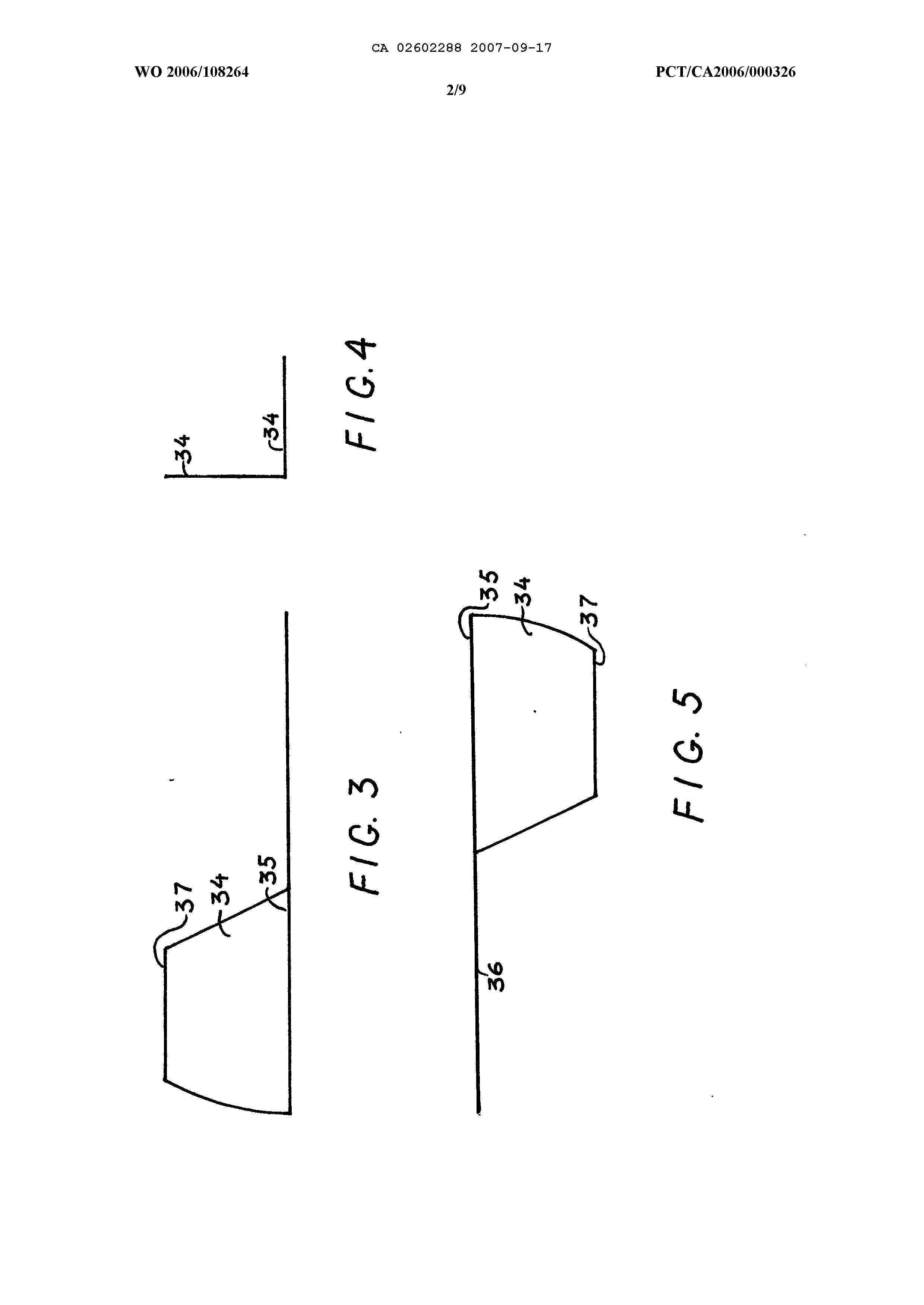
BRIEF DESCRIPTION OF THE DRAWING FIG.5 is FIG.6 is FIG. 1; FIG. 1 is a frontal view of the system module for harvesting the kinetic energy from unidirectional flow of water; FIG. 2 is a top view of FIG. 1; FIG.3 is a frontal view of the paddle; FIG.4 is a side view of FIG. 3; a top view of FIG. 3; a fi'ontal view of the vertical arrangement of an array of the system modules of FIG.7 is a plane top view of the horizontal backslash arrangement of an array of the system modules of FIG. 1; FIG.8 is a plane top view of the horizontal forward slash arrangement of an array of the system modules of FIG. 1; FIG.9 is a plane top view of the system module for harvesting the kinetic energy of tides; FIG. 10 is a frontal view of the system module for harvesting the kinetic energy of wind; FIG. 11 is a plane top view of FIG. 10; CA 02602288 2010-01-21 FIG. 12 is a schematic view of a paddlewheel wind turbine; FIG. 13 is a frontal view of the bidirectional venturi-shaped system module for harvesting the kinetic energy of tides; FIG. 14 is atop view of FIG. 13.
DETAILED DESCRIPTION OF THE INVENTION Embodiment A The embodiment A is the system assembly capable of harvesting the kinetic energy from unidirectional flow of water for producing electricity. The system comprises an array of interconnected submersible units or modules to harness water power. Each system module (see FIGS. 1 and 2) contains a water current energy converter positioned in a protecting housing 21 with proper bearings.
A converter consists of a detachable vertical axis hydro-turbine 22, the detachable electrical generator 23, and detachable water current deflector 24.
The turbine 22 is essentially a paddlewheel having an arrangement of two sets 25 and 26 of attached paddles with asymmetrically fixed blades to increase torque and power output. The first set 25 of paddles with floatable blades is located above the working wheel 27, as the second set 26 of paddles with sinkable blades is located below the working wheel 27. A plurality of radial spokes 28 connects the working wheel's rim 29 to the hub 30. Such radial spokes increase the integrity and structural strength of the turbine.
Both sets 25 and 26 of the paddles are attached to the working wheel 27 by support members 31 such as padlocks or the like. These support members are fixedly mounted to the rim 29 and, possibly, to the hub 30 of the working wheel 27 and have built in stops, which allow the free rotation of the paddles in the right angle range. Generally, each set may comprise any number of paddles (preferably three) made from any suitable material, which is strong and lightweight.
The working wheel's hub 30 is mounted via bearings on its ends over an inner vertical axis 33 that is nonrotatably attached by its ends to the protective housing 21.
As shown in FIGS.3 through 5, the blades 34 are asymmetrically fixed by their leading edge 35 to the pole 36 at both ends and have a mutually perpendicular orientation. Such orientation of blades provides a positive feedback minimizing the blades' friction and maximizing the turbine's performance.
To ensure the most efficient utilization of the current flow, the blades 34, preferably, have a profile of the partial segment (see FIG.3) with the distance between parallel leading 35 and a trailing 37 edges not exceeding the hall of the segment's radius.
The blades may be manufactured from any suitable material, such as a steel, aluminum, plastic or fiberglass, which provides sufficient buoyancy for the floatable blades, and reasonable gravity for the sinkable blades.
CA 02602288 2010-01-21 The flow deflector 24 (see FIGS. 1 and 2) funnels incoming water current through the working side 38 of the turbine 22 and protects the resting (opposite) side 39 of the turbine 22 from moving water. It further decreases the blades' friction, reduces resistance to the turbine rotation, and increases the fluid velocity through the turbine thereby enhancing the efficiency and power output of the converter. The blades 34 extend beyond supporting members 31, mounted on the rim 29 thereby increasing torque to spin the turbine.
As discussed earlier, the efficiency of the vertical axis turbine increases with the degree of difference between a drag force created by turbine's blades and their frictional force.
The greater the cross sectional area of the blades on the working side of the paddlewheel that transfers kinetic energy to the turbine and the lower the surface area of the paddlewheel on the opposite side, the greater the efficiency of the turbine. The high efficiency of the presented turbine comes from creating maximum drug force by vertically oriented blades on the power generating side 38 and practically zero frictional force produced by horizontally oriented blades on the resting side 39 of the paddlewheel.
When the water is not flowing the sinkable blades of the lower paddles, located below the working wheel, are partially open via the force of gravity creating 45-degree angles between their surfaces and the vertical axis of the turbine. When water flows against the partially opened blades on the power generating side of the paddlewheel the water current applies as an opening force against the blades. The flow deflector 24 protects the resting (opposite) part of the turbine from moving water and, therefore, eliminates applying a force against the blades on the opposite side of the paddlewheel. Two forces (gravity and water flow) start to turn the blades on the power generating side toward their vertical position. The cross flower area is increasing and the turbine begins spinning. At the same time, because of their mutually perpendicular orientation, the blades on the opposite side of the paddles are turning toward their horizontal position, decreasing the frictional force.
This creates a positive feedback resulting in further increasing the turbine's spinning.
When the blades reach the vertical position, stops prevent paddles from turning further.
As a result, the vertically oriented blades create the maximum drug force while the frictional force of the horizontally oñented blades is negligible thereby producing the high efficiency of the presented turbine.
The upper paddles, located above the wheel, work in a similar way. The only difference is that a buoyant force applies to the floatable blades of the upper paddles instead of a gravitational force applied to the sinkable blades of the lower paddles.
The presented vertical axis paddlewheel turbine is far more effective in its operation than is a prior art: (1) the amount of frictional force is negligible because the frictional area of the horizontally oriented blades is close to zero; (2) torque is gained by an increase in horizontal distance instead of an increase in vertical distance, which allows it to be used in shallow water currents with a very low head; (3) it is of simple construction and, therefore, inexpensive to produce; (4) it can be made to have only a small number of wearing parts and thus has a long service life; (5) it is capable of handling large volumes of water without becoming too bulky.
CA 02602288 2010-01-21 The electrical generator 23 transforms the rotational energy of the turbine into electricity.
A generator pulley 40 is coupled to a generator 23. A belt 41 rotatably couples the generator pulley 40 to the paddlewheel's rim 29, which serves as a gear thereby eliminating the need for an underwater gearing speed increaser, which would otherwise be required to connect a slowly spinning paddlewheel's hub to an electrical generator.
The belt in the present example is a V-shaped belt. Alternatively, the rim may be coupled to an electrical generator by any suitable means such as a belted tooth-pin transmission or other driven means, as well as any suitable submersible electrical generator may be employed.
The system module's protecting housing 21, shown in FIGs.1 and 2, is a strong steel frame having a shape of the right trapezoid prism, which supports the turbine 22, deflector 24, and the electrical generator 23. Additionally, the protecting housing includes the detachable filter and screen panels. The filter panels, made of steel bars, cover the front, rear and top entrances of the frame to prevent clogging of the converter by submerged objects (debris) carried by water current. The size of the filter opening is smaller than the spacing between the turbine blades and frame so that any particular matter that passes through the filter can freely pass through the turbine and out the module. The screen panels cover the frame's side entrances and serve both to improve the efficiency of the turbine by creating a described earlier funneling channel together with a flow deflector 24, and to protect the converter from debris.
In order to properly position and secure the system module to a river bed, the protective housing may be bolted to the ballast panel 42 having anchoring means 43, for example concrete blocks. Such a bolted structure allows it to be easily mounted and adjusted to the riverbed profile.
One or more modules can be anchored at various locations in a river or ocean for the purpose of generating electricity, pumping water or operating mechanisms or the like.
The system's modularity allows it to be assembled by bolts, screws and other conventional anchoring pieces. Such gives a time advantage for assembly and maintenance. The array of these modules may be arranged side by side, so as to intersect any cross sectional area of the flow nearly completely, thus providing versatile forms of hydroelectric power systems such as a vertical (FIG. 6), horizontal back slash (FIG. 7), horizontal forward slash (FIG. 8), or any combinations of the above arrangements of the system modules, which are inexpensive to build, install and maintain.
A vertical configuration of the modular system can exploit a common generator 23 for a number of modules providing an additional flexibility to build and maintain the power system (see FIG. 6). The modules may be connected to an electric generator 23 in any suitable manner, such as by a belted transmission and a vertical common shaft CA 02602288 2010-01-21 It must be appreciated that during the assembling of the systems, illustrated in FIGS. 7 and 8, the common sharp angle filter protection 47 against submerged objects (debris) is created automatically, thereby providing a significant advantage to the prior art.
The electricity produced by the system is transmitted through the flexible underwater cables to the shore. After employing the appropriate voltage regulator and transformers, the generated power then is supplied to the consumers via the power-distributing network.
The nature of the system according to the present invention is such that it need never totally block the natural flow of the river. There is no need for the system to dominate the landscape, endanger fish or interfere adversely with recreational pursuits such as fishing or boating. The system does not change the character of the water stream or create any harmful by-products. Unlike previous efforts to generate electricity from moving fluid, the present invention is practical and economical because its design uses both a new turbine, which surpasses the efficiencies of other known fluid driven turbines, and a durable simple construction to achieve long term unattended operation.
Embodiment B The embodiment B is the system assembly comprising an array of interconnected submersible units or modules capable of harvesting the kinetic energy of tides that alternate direction of their movement on 180 degrees. Each system unit or module (see FIG. 9) contains a water current energy converter positioned in a protecting housing A converter consists of a detachable vertical axis hydro-turbine 22, analogous to that described in the embodiment A, the detachable electrical generator 23, and two detachable flow deflectors 53 and 54.
Symmetrically located in inlet/outlet areas of the module, the flow deflectors 53 and 54 are secured to the housing in a pivotal manner. The free end of each flow deflector is able to rotate in the sector restricted by the filter panels 55, 56 and screen panels 57, 58 incorporated into protecting housing 50. The arrangement of the flow deflectors is such that they are urged by incoming flow of water to rotate toward the screen panels while the outgoing flow of water rotates the flow deflectors towards the filter panels thus creating the funneling channel, analogous to described in the embodiment A, on the energy generating side of the paddlewheel.
When the flow of tidal currents reverses, the flow of water through the funneling channels also reverses. However, the paddlewheel continues to rotate in the same direction. Hence, the turbine provides a unidirectional rotation regardless of the directions of the tidal currents.
The system module's protecting housing 50 is a strong steel frame having a symmetrical shape of the right rhomboid prism, which supports the turbine 22, flow deflectors 53 and 54, and the electrical generator 23.
CA 02602288 2010-01-21 Embodiment C The embodiment C is the system assembly comprising an array of interconnected units or modules capable of harvesting the kinetic energy of wind.
Each system unit or module depicted in FIGS. 10 and 11 contains a wind energy converter positioned in a housing A converter consists of a detachable vertical axis turbine 61 with a set of paddles 62 located below the working wheel, and the detachable electrical generator 23, connected to the wheel's outer diameter (rim) 29, as shown in FIGS. 10 and 11.
The system module's housing 60 is a strong steel frame having a shape of the right square prism. Additionally, the housing includes the detachable screens to prevent collisions with birds.
This vertical axis wind turbine, illustrated separately in FIG. 12, works in a similar way as a turbine for water applications described in the embodiments A and B. The turbine's paddles and blades can be produced from any suitable lightweight and strong material, and are of the same design as shown in FIGS. 3 through The presented turbine provides unidirectional rotation for any wind direction and it does not have to be directed into the wind. In contrast, the conventional horizontal axis turbines must be rotated to face the wind direction.
For wind power applications, a plurality of modules may be stacked vertically (similarly to FIG. 6). Each vertical stack may be supported in any suitable manner and can be anchored to the ground by guy wires. Any desired number of modules may be provided in any desired number of vertical stacks. One or more electrical generators may be provided in communication with modules. A generator may be individually associated with each module, or plural modules may be connected via a suitable transmission to a single generator, as illustrated in FIG. 6.
The array of modular systems may be located in any suitable windy site, as is known in the art, for example for locating traditional windmill-type wind farms. At the same time, the flexibility of the present invention allows it to be used in many locations, in which traditional horizontal axis turbines cannot be used, such as building rooftops, telecommunications, water and power line towers, etc.
The wind turbine's design having one set of paddles, like that shown in FIG. 12, is also exceptionally suitable in very shallow water currents were none of the prior art designs can be used.
Embodiment D The embodiment D is the system assembly comprising an array of interconnected venturi-shaped bidirectional converting modules capable of harvesting the kinetic energy of tides.
CA 02602288 2010-01-21 Il Power available from a turbine increases as the cube of the velocity. If the velocity is doubled, the available power then increases by a factor of eight. It is therefore important to make use of velocities that are as high as possible, which would enable the number of turbines to be significantly reduced, and this would have a marked effect on the capital cost. This is achieved through the use of the venturi-shaped bidirectional converting modules shown in FIGS. 13 and 14.
This module consists of a detachable vertical axis hydro-turbine 22, analogous to the one described in the embodiment A, the detachable electrical generator 23, filter panels 81 and 82, curved side screen panels 83 and 84, the fiat bottom screen panel 85, the fiat top screen panel 86, and a pair of flow deflectors 87 and 88. The flow deflectors are symmetrically located in the inlet/outlet areas of the module and secured to the venturishaped protective housing 80 in a pivotal manner.
The free end of each flow deflector is able to rotate inside the sector restricted by the stops 91, 92 and stops 93, 94, which are incorporated into protective housing 80. The arrangement of the deflectors is such that they are forced to rotate by the incoming flow of water toward the stops 92 and 93, while the outgoing flow of water rotates the deflectors toward the stops 91 and 94. This arrangement together with the screen panels 83, 84 and 85, 86 creates venturi-shaped funneling channels with a gradually contracting rectangular cross-section that heads to the turbine blades on the energy generating side of the paddlewheel.
When the flow of a tidal current reverses, the flow of water through the funneling channels also reverses. However, the paddlewheel continues to rotate in the same direction. Hence, the turbine maintains a unidirectional rotation regardless of the direction of tidal currents.
The system module's protecting housing 80 is a venturi-shaped strong steel frame, which supports ail of the above-mentioned components of the module. The filter panels 81 and 82, made of steel bars, cover V-shaped inlets of the housing 80 to prevent clogging of the of the converter by submerged objects (debris) carried by water current.
The present invention is not to be limited by what has been particularly shown and described, except as indicated by the appended claims.
CA 02602288 2011-05-26 THE EMBODIMENTS OF THE INVENTION IN WHICH AN EXCLUSIVE A modular system for producing electricity from the channel, river, ocean or tidal water currents and wind is disclosed. The embodiments of the system comprise a set of interconnected modules. Each module contains a fluid flow energy converter positioned in a protecting housing. A converter consists of a vertical axis underwater hydro-turbine or wind turbine, connected to the electrical generator. The turbine is essentially a paddlewheel having an arrangement of attached paddles with mutually perpendicularly oriented asymmetric blades that are fixed to the poles at both ends. Such orientation of blades provides a positive feedback minimizing the blades' friction while maximizing a drag force and maximizing the turbine's efficiency. The electrical generator transforms the rotational energy of the turbine into electricity. An array of modules may be arranged side by side, thus providing versatile configurations of submersible hydroelectric or wind power systems, which are inexpensive to build, install and maintain. Claim 1: A vertical axis paddlewheel type turbine for converting kinetic energy of river or ocean currents into electricity consisting of:
a. A working wheel, comprising a hub mounted via bearings on an inner vertical axis to a protecting housing b. A first set of paddles located above said working wheel and comprising a pair of fioatable blades, having a partial segment profile, which are asymmetrically fixed by their leading edges to a pole at both ends and have a mutually perpendicular orientation c. A second set of paddles located below said working wheel and compñsing a pair of sinkable blades, having a partial segment profile, which are asymmetrically fixed by their leading edges to a pole at both ends and have a mutually perpendicular orientation d. Paddle support members fixedly mounted to the rim and hub of said working wheel e. Stops, built in the said paddle support members, limiting the free rotation of said paddles in the ninety degree angle range f. A plurality of radial spokes connecting said working wheel's ñm to said working wheel's hub.
Claim 2: A vertical axis paddlewheel type turbine for converting kinetic energy of river or ocean currents into electricity consisting of:
a. A working wheel, comprising a hub mounted via bearings on an inner vertical axis to a protecting housing b. A set of paddles located above said working wheel and comprising a pair of float,able blades, having a partial segment profile, which are asymmetrically fixed by their leading edges to a pole at both ends and have a mutually perpendicular orientation c. Paddle support members fixedly mounted to the tire and hub of said working wheel d. Stops, built in the said paddle support members, limiting the free rotation of said paddles in the ninety degree angle range e. A plurality of radial spokes connecting said working wheel's rim to said working wheel's hub.
Claim 3: A vertical axis paddlewheel type turbine for converting kinetic energy of river or ocean currents into electricity consisting of:
a. A working wheel, comprising a hub mounted via bearings on an inner vertical axis to a protecting housing b. A set of paddles located below said working wheel and comprising a pair of sinkable blades, having a partial segment profile, which are asymmetrically fixed by their leading edges to a pole at both ends and have a mutually perpendicular oñentation CA 02602288 2011-05-26 c. Paddle support members fixedly mounted to the rim and hub of said working wheel d. Stops, built in the said paddle support members, limiting the free rotation of said paddles in the ninety degree angle range e. A plurality of radial spokes connecting said working wheel's rim to said working wheel's hub.
Claim 4: A submersible module for converting kinetic energy of tides into electricity comprising:
a. The vertical axis paddlewheel-type turbine recited in claim 1, which is incorporated into a protecting housing b. A protecting housing, having a form of the right rhomboid prism with sharp angle inlets of said housing c. An electrical generator located in said housing d. A pair of plain screens covering the right and left sides of said housing e. A set of detachable filter panels, covering the front, rear and top sides of said housing to prevent clogging of the said module by submerged objects carried by water currents f. A pair of flow deflectors symmetrically located in inlet/outlet areas of the module, secured to the housing in a pivotal manner enabling their free ends to rotate in the sector restricted by the said screen panels and said front and rear filter panels, and having a such arrangement that they are forced by incoming flow of water to rotate said deflectors toward said screens while the outgoing flow of water rotates said deflectors towards the filters g. A pair of funnel channels, which are incorporated with said flow deflectors and said screens for directing incoming water currents through the working part of said turbine and protecting the opposite part of said turbine from moving water, thus providing a unidirectional rotation of said turbine regardless of the directions of the tidal currents h. Means for transmitting torque developed by said turbine to said electrical generator.
Claim 5: A submersible module for converting kinetic energy of tides into electricity comprising:
a. The vertical axis paddlewheel-type turbine recited in claim 2, which is incorporated into a protecting housing b. A protecting housing, having a form of the right rhomboid prism with sharp angle inlets of said housing c. An electrical generator located in said housing d. A pair of plain screens covering the right and left sides of said housing e. A set of detachable filter panels, covering the front, rear and top sides of said housing to prevent clogging of the said module by submerged objects carried by water currents f. A pair of flow deflectors symmetrically located in inlet/outlet areas of the module, secured to the housing in a pivotal manner enabling their free ends to rotate in the sector restricted by the said screen panels and said front and rear filter panels, and CA 02602288 2011-05-26 having a such arrangement that they are forced by incoming flow of water to rotate said deflectors toward said screens while the outgoing flow of water rotates said deflectors towards the filters g. A pair of funnel channels, which are incorporated with said flow deflectors and said screens for directing incoming water currents through the working part of said turbine and protecting the opposite part of said turbine from moving water, thus providing a unidirectional rotation of said turbine regardless of the directions of the tidal currents h. Means for transmitting torque developed by said turbine to said electrical generator.
Claim 6: A submersible module for converting kinetic energy of tides into electricity compñsing:
a. The vertical axis paddlewheel-type turbine recited in claim 3, which is incorporated into a protecting housing b. A protecting housing, having a form of the fight rhomboid prism with sharp angle inlets of said housing c. An electrical generator located in said housing d. A pair of plain screens covering the fight and left sides of said housing e. A set of detachable filter panels, covering the front, rear and top sides of said housing to prevent clogging of the said module by submerged objects carried by water currents f. A pair of flow deflectors symmetrically located in inlet/outlet areas of the module, secured to the housing in a pivotal manner enabling their free ends to rotate in the sector restricted by the said screen panels and said front and rear filter panels, and having a such arrangement that they are forced by incoming flow of water to rotate said deflectors toward said screens while the outgoing flow of water rotates said deflectors towards the filters g. A pair of funnel channels, which are incorporated with said flow deflectors and said screens for directing incoming water currents through the working part of said turbine and protecting the opposite part of said turbine from moving water, thus providing a unidirectional rotation of said turbine regardless of the directions of the tidal currents h. Means for transmitting torque developed by said turbine to said electrical generator.
Claim 7: A vertical axis paddlewheel type turbine for converting kinetic energy of wind into electricity consisting of:
a. A working wheel, comprising a hub mounted via bearings on an inner vertical axis to a protecting housing b. A set of paddles located below said working wheel and comprising a pair of blades, having a partial segment profile, which are asymmetrically fixed by their leading edges to a pole at both ends and have a mutually perpendicular orientation c. Paddle support members fixedly mounted to the rim and hub of said working wheel CA 02602288 2011-05-26 d. Stops, built in the said paddle support members, limiting the free rotation of said paddles in the ninety degree angle range e. A plurality of radial spokes connecting said working wheel's rim to said working wheel's hub.
Claim 8: A module for converting kinetic energy of wind into electricity comprising:
a. A frame protecting housing, having a form of the right square prism b. An electrical generator located in said housing c. The vertical axis paddlewheel-type turbine recited in claim 7, which is incorporated into a protecting housing d. Means for transmitting torque developed by said turbine to said electrical generator e. A set of detachable screens to prevent collisions with birds.
Claim 9: A submersible bidirectional module for converting kinetic energy of tidal currents into electricity comprising:
a. A venturi-shaped frame protecting housing, which is connected on both ends to V-shaped inlets b. An electrical generator attached to said housing c. A vertical axis paddlewheel-type turbine recited in claim 1, which is incorporated into said housing d. A pair of curved screen panels covering the right and left sides of said housing e. A pair of fiat screen panels covering the top and bottom sides of said housing f. A set of filter panels covering said V-shaped inlets of said housing to prevent clogging of the said module g. A pair of flow deflectors symmetrically located inside inlet/outlet areas of the said module, and secured to said housing in a pivotal manner thus enabling the free ends of said flow deflectors to rotate in the sectors restricted by stops, which are incorporated into said housing and have such an arrangement that said flow deflectors are forced by incoming and outgoing flows of water to rotate in the direction of the water flow h. A pair of funnel channels, with a gradually contracting rectangular cross-section, which are incorporated with said flow deflectors and said screen panels for directing incoming water currents through the working part of said turbine, protecting the opposite part of said turbine from moving water, and providing a unidirectional rotation of said turbine regardless of the directions of tidal currents i. Means for transmitting torque developed by said turbine to said electrical generator.
Claim 10: The module of claim 9, wherein said means for transmitting torque developed by said paddlewheel type turbine to said electrical generator consists of:
a. A generator pulley coupled to said generator b. A belt rotatably coupling said generator pulley to the recited in claim 1 working wheel's rim, which serves as a gear.
CA 02602288 2011-05-26 Claim 11: A submersible bidirectional module for converting kinetic energy of tidal currents into electricity comprising:
a. A venturi-shaped frame protecting housing, which is connected on both ends to V-shaped inlets b. An electrical generator attached to said housing e. A vertical axis paddlewheel-type turbine recited in claim 2, which is incorporated into said housing d. A pair of curved screen panels covering the right and left sides of said housing e. A pair of fiat screen panels covering the top and bottom sides of said housing f. A set of filter panels coveñng said V-shaped inlets of said housing to prevent clogging of the said module g. A pair of flow deflectors symmetrically located inside inlet/outlet areas of the said module, and secured to said housing in a pivotal manner thus enabling the free ends of said flow deflectors to rotate in the sectors restricted by stops, which are incorporated into said housing and have such an arrangement that said flow deflectors are forced by incoming and outgoing flows of water to rotate in the direction of the water flow h. A pair of funnel channels, with a gradually contracting rectangular cross-section, which are incorporated with said flow deflectors and said screen panels for directing incoming water currents through the working part of said turbine, protecting opposite part of said turbine from moving water, and providing a unidirectional rotation of said turbine regardless of the directions of tidal currents i. Means for transmitting torque developed by said turbine to said electrical generator.
Claim 12: A submersible bidirectional module for converting kinetic energy of tidal currents into electricity comprising:
a. A venturi-shaped frame protecting housing, which is connected on both ends to V-shaped inlets b. An electrical generator attached to said housing c. A vertical axis paddlewheel-type turbine recited in claim 3, which is incorporated into said housing d. A pair of curved screen panels covering the right and left sides of said housing e. A pair of fiat screen panels covering the top and bottom sides of said housing f. A set of filter panels covering said V-shaped inlets of said housing to prevent clogging of the said module g. A pair of flow deflectors symmetrically located inside inlet/outlet areas of the said module, and secured to said housing in a pivotal manner thus enabling the free ends of said flow deflectors to rotate in the sectors restricted by stops, which are incorporated into said housing and have such an arrangement that said flow deflectors are forced by incoming and outgoing flows of water to rotate in the direction of the water flow h. A pair of funnel channels, with a gradually contracting rectangular cross-section, which are incorporated with said flow deflectors and said screen panels for directing incoming water currents through the working part of said turbine, CA 02602288 2011-05-26 i.
protecting opposite part of said turbine from moving water, and providing a unidirectional rotation of said turbine regardless of the directions of tidal currents Means for transmitting torque developed by said turbine to said electrical generator.
Claim 13: A plurality of submersible bidirectional converting modules of claim 9, which are stacked vertically to provide a continuous tower configuration for converting kinetic energy of tidal currents into electricity.
Claim 14: A plurality of submersible bidirectional converting modules of claim 9, which are stacked vertically to provide a continuous tower configuration for converting kinetic energy of tidal currents into electricity, and comprising a common vertical shaft to connect said plural modules to a single electrical generator located below the water surface.
Claim 15: A plurality of submersible bidirectional converting modules of claim 9, which are stacked vertically to provide a continuous tower configuration for converting kinetic energy of tidal currents into electricity, and comprising a common vertical shaft to connect said plural modules to a single electrical generator located above the water surface.