AUXILIARY WATER TANK AND PUMP ASSEMBLY FOR A VEHICLE
WO 2007/106147 CA 02636168 2008-08-14 -IPCT/US2006 43094 AUXILIARY WATER TANK AND PUMP ASSEMBLY FOR A VEHICLE BACKGROUND OF THE INVENTION I. Field of the Invention The present invention relates generally to vehiclemounted concrete mixing and dispensing systems and, more particularly, to on-board auxiliary fluid supply systems employed to supply water for washout or adding water to a concrete mix. Specifically, the present invention relates to a pump-operated on-board auxiliary fluid supply system that eliminates the need for a pressurized tank and is self purging of residual fluid.
Il. Related Art Transit concrete mixing trucks, sometimes referred to as ready-mix trucks, have long been in use. They are equipped with large chassis-mounted rotatable mixing drums for mixing and dispensing a quantity of concrete.
The drums typically are mounted on an incline and have an opening in the upper end for receiving ingredients to be mixed and discharging mixed concrete products. Loading is accomplished through a charge hopper which extends a distance into the opening of the drum. The drum is further provided with internal helical flights or fins extending around its internal surface which acts to mix the concrete when the drum is caused to rotate in one direction and cause the concrete to be discharged out of the opening when the rotation of the drum is reversed.
The upper portion of the drum includes a ring and roller system for drum support and rotation that is carried by a heavy pedestal support assembly.
After mixing and discharge, such concrete mixing drums retain an amount of residual concrete on the mixing fins and inner drum surface and discharge chutes which needs to be periodically washed out to prevent it from curing and hardening inside the drum and on external WO 2007/106147 CA 02636168 2008-08-14 PCT/US2006/043094 chutes. Therefore, it has become part of the operating routine to wash the interior of the drum and the discharge chutes one or more times per day. In addition, it may be necessary to add additional makeup water to a mix in the drum prior to discharge.
In conjunction with the use of makeup or washout water on transit concrete mixing trucks, it has further become a common practice to provide a water supply on the vehicle. The supply has included a water tank that has been typically pressurized to 50 psi or higher by a supply of air from a compressor carried on the truck.
This, in turn, supplies water under pressure for washout or other uses through hoses and a valving system in a well-known manner.
Such a prior system is :illustrated in Figures la and lb in which a concrete mixer truck, generally at I0, having a mixing drum 12 and discharge chute 14 is provided with a pressurizable auxiliary water tank 16 mounted on the vehicle. As seen in Figure lb, the auxiliary water tank 16 includes an air inlet valve that controls the flow of air under pressure from a pressure source (not shown) through an air supply line (also not shown). An air pressure regulator with gauge 22 is provided, together with a pressure relief or popoff valve at 24, which prevents over-pressurization of the system. A discharge outlet pipe or hose is provided at 26 suitably valved at 28. The system may be purged by using pressurized air to clear the hose or pipe 26.
More recently, however, goverrnnent regulations have curtailed the use of such pressurized tanks in many areas and so it would be desirable to eliminate the need for pressurization of the tank without diminishing the washout or easy purge capabilities of the system.
WO 2007/106147 CA 02636168 2008-08-14 PCT/US2006/043094 SUMMARY OF THE INVENTION By means of the present invention, there is provided a self-purging auxiliary fluid supply system for supplying water for washout or adding to batches in a truck-mounted concrete mixing drum. The system includes a truck-mounted fluid reservoir for containing a quantity of water, the reservoir being connected to supply nonpressurized fluid to a pump assembly. The pump assembly includes an air-operated diaphragm pump apparatus for supplying auxiliary fluid from the fluid reservoir under pressure to a discharge assembly which connects to a conventional washout/supply system associated with the operation of the mixing drum. The fluid supply system is provided with valving which enables it to quickly integrally purge itself after use.
Several embodiments are shown with different locations for the mounting of the pump of the invention.
The system is designed for ease of manufacture or as a convenient retrofit system on existing transit concrete mixing trucks. The pump and piping system eliminate the need for pressurizing the reservoir tank and facilitate the draining or purging of associated water lines to prevent freezing in cold weather. A typical diaphragm pump of the invention uses air at about i00 psig to operate the pump and can supply up to 25 gpm of water at a pressure of about i0 psig for water injection or about 8 gpm at about 75 psig for washout.
BRIEF DESCRIPTION OF THE DRAWINGS In the drawings, wherein like numerals depict like parts throughout the same:
Figure la is a side elevational view of a transit concrete mixing truck carrying an auxiliary water system in accordance with the prior art; Figure lb is an enlarged side elevational view of a WO 2007/106147 CA 02636168 2008-08-14 4PCT/US2006/043094 prior art auxiliary water tank from the system of Figure la; Figure 2 is an enlarged partial perspective view of an embodiment of an auxiliary water system in accordance with the present invention which utilizes a side pump mounting; Figure 3a is a view similar to Figure 2 illustrating an alternate embodiment of the auxiliary water system of the present invention; Figure 3b is an enlarged frontal view of the diaphragm pump of Figure 3a; Figure 4 is an enlarged perspective view of another embodiment of the present invention using a tank-mounted pump; Figure 5 is a perspective view of another embodiment which utilizes a side pump mounting; and Figure 6 is an alternate embodiment of a water supply tank equipped with an additive supply tank.
DETAILED DESCRIPTION Certain embodiments of the present invention will be described with reference to drawing figures. They represent examples of an auxiliary water supply system for a transit concrete mixing truck which provides high pressure water for washout or additional water to be added to the drum. The embodiments described are meant as examples and are not intended to limit the inventive concepts.
It is an important aspect of the present invention that the need for an expensive pressurized water supply tank is eliminated. In addition, the invention further provides a rapid self-purging feature to purge the system of water after use.
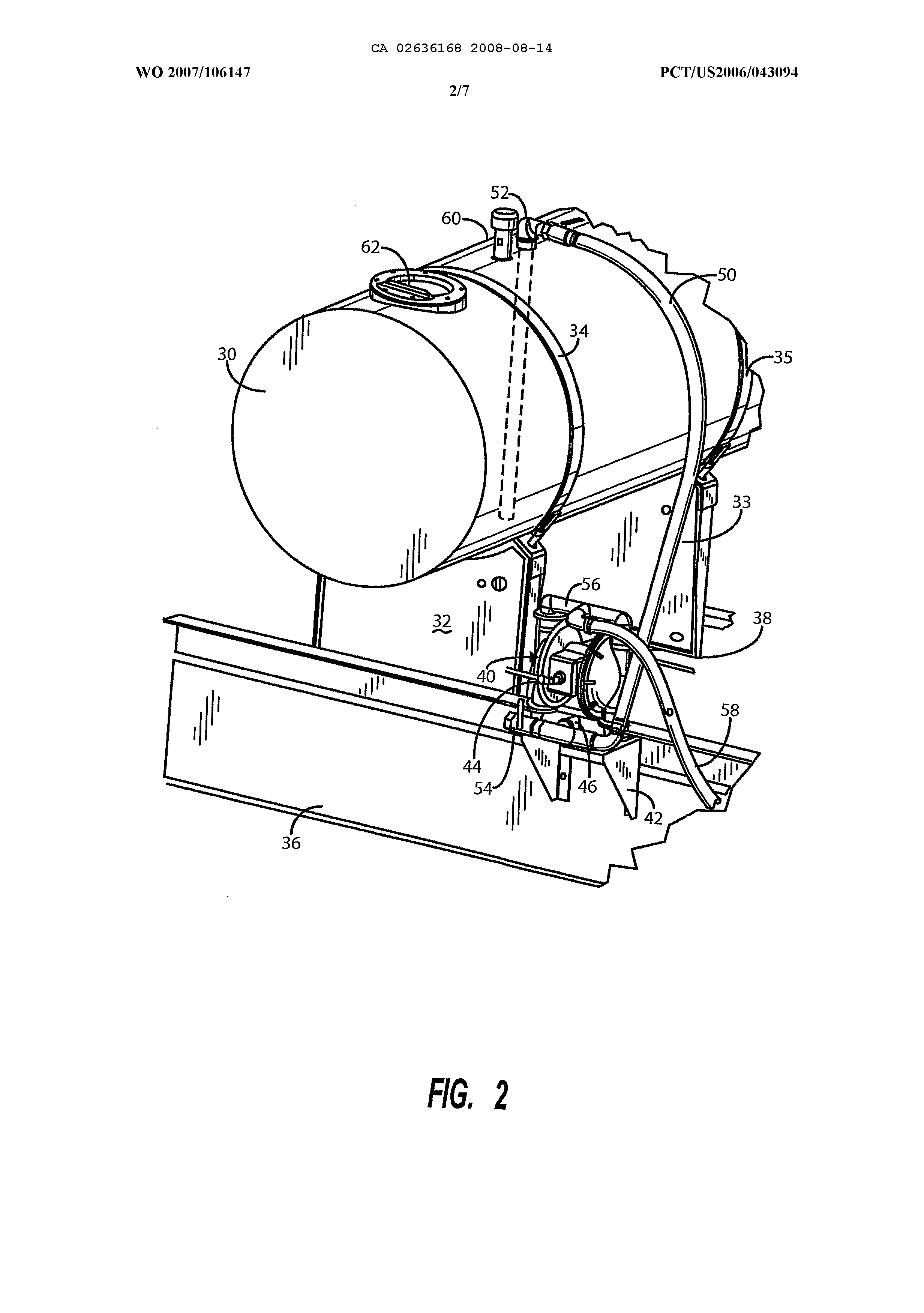
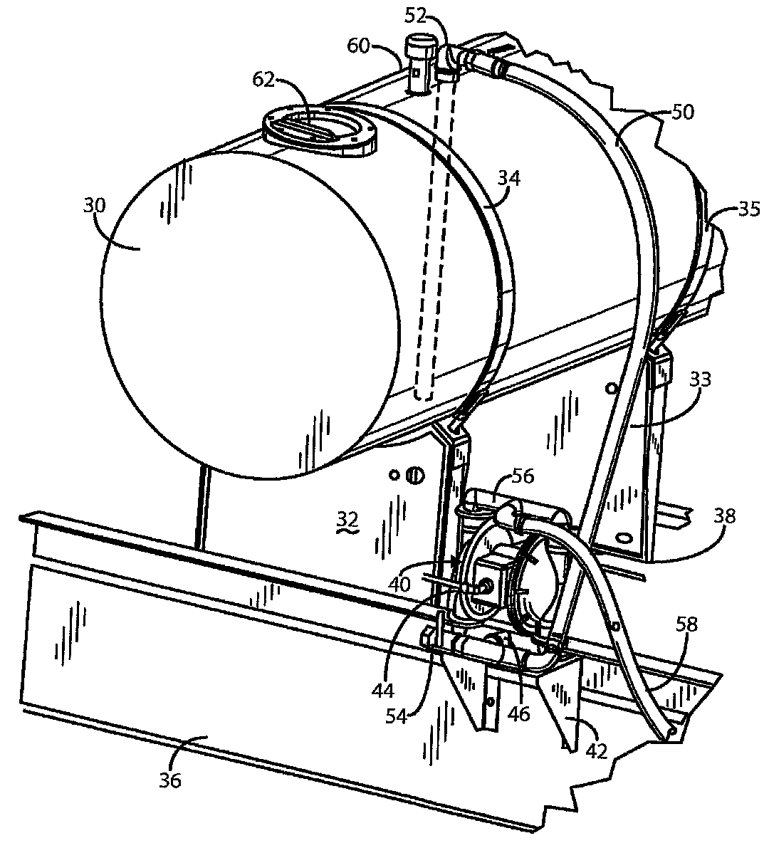
Figure 2 depicts an enlarged partial perspective view of an embodiment of the invention which includes a WO 2007/106147 CA 02636168 2008-08-14 PCT/US2006/043094 side or frame-mounted pump. The system includes an auxiliary water supply tank 30 which may be fabricated from metal or non-metal materials and is shown carried by support pedestals or saddles 32, 33 fixed thereto by heavy straps 34, 35. Saddles 32, 33, in turn, are fixed to truck frame members 36, 38, respectively. An airoperated diaphragm pump 40 is mounted on a bracket 42 fixed to the truck frame member 36. An air supply inlet connection is shown at 44, which connects to an air pressure supply tank or accumulator which is pressurized by a conventional source of high pressure air such as a compressor (not shown) used to operate diaphragm pump The pump 40 has a suction inlet at 46 connected as by a tee 48, one side of which is connected to a water feed line 50 which, in turn, is connected to the tank 30 at 52.
The tank discharge is preferably a top discharge, bottom draw system using a conventional bottom draw standpipe tube (not shown) that is connected to outlet 52 at the top and extends to the bottom of the tank. This greatly facilitates hose system drainage after use.
However, a bottom discharge arrangement can also be used.
The tee 4@ also leads to a manually operated ball valve 54 used to drain and purge the system. The pump discharge outlet manifold shown at 56 is connected to a pump discharge hose 58 usable for washout or adding water to the drum. The water tank 30 is further provided with a breather vent 60 and fill opening 62. The pump discharge hose 58 is connected to conventional suitable control valves (not shown) in a well known manner.
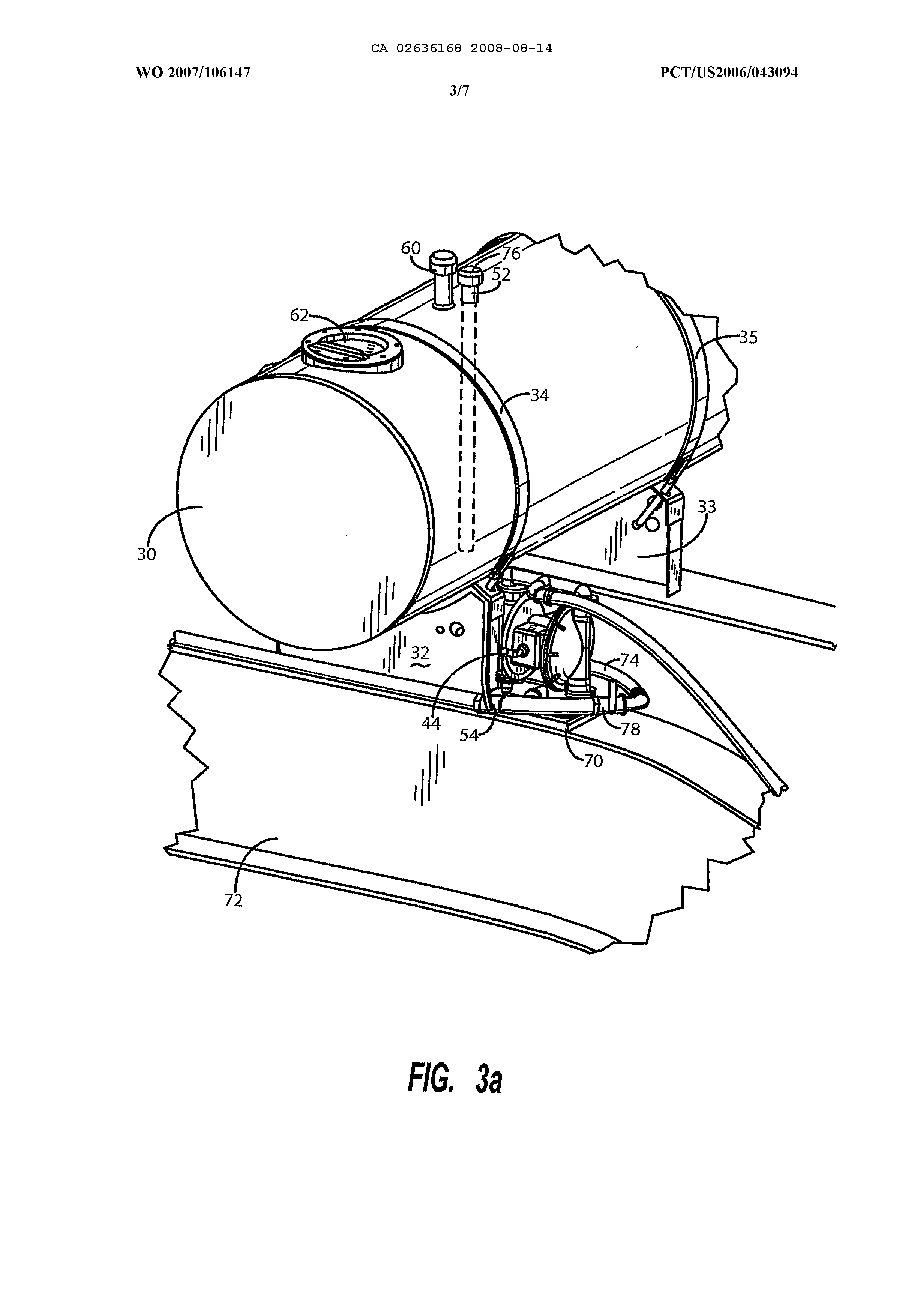
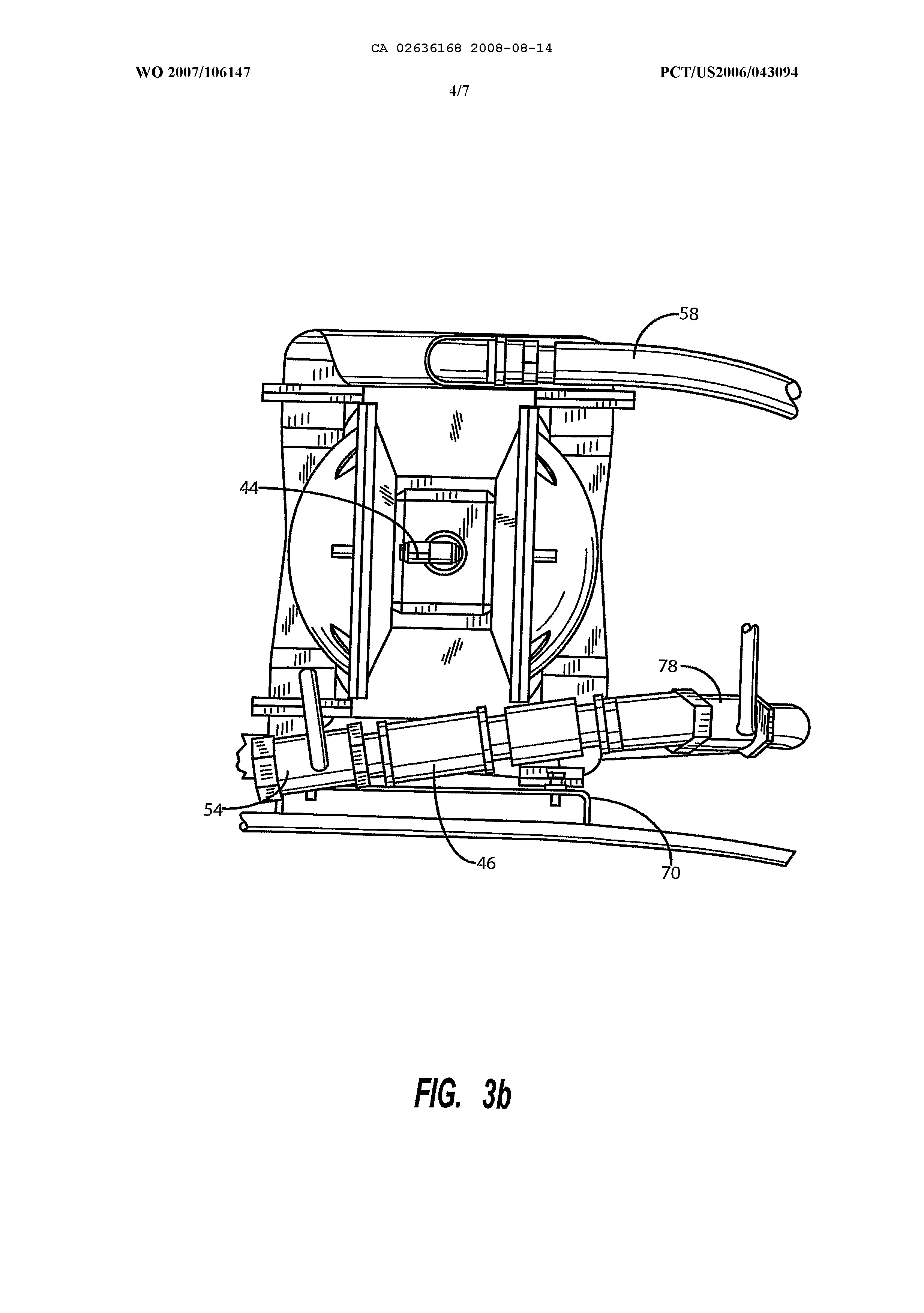
Figures 3a and 3b depict an alternative trailermounted embodiment which uses a mounting bracket mounted flush with trailer frame member 72. In this embodiment, the water feed line 74 ïs shown as being WO 2007/106147 CA 02636168 2008-08-14 6PCT/US2006/043094 connected to a tank discharge outlet on the bottom of the tank 30 and the upper outlet 52 is suitably capped at 76.
Of course, a top discharge, bottom-draw connection could also be used. A ball valve is provided in the intake line at 78. As best seen in Figure 3b, the input/drain line between valves 78 and 54 is inclined slightly downward to valve 54. This is to assure easy drainage when valve 54 is opened after the system is used.
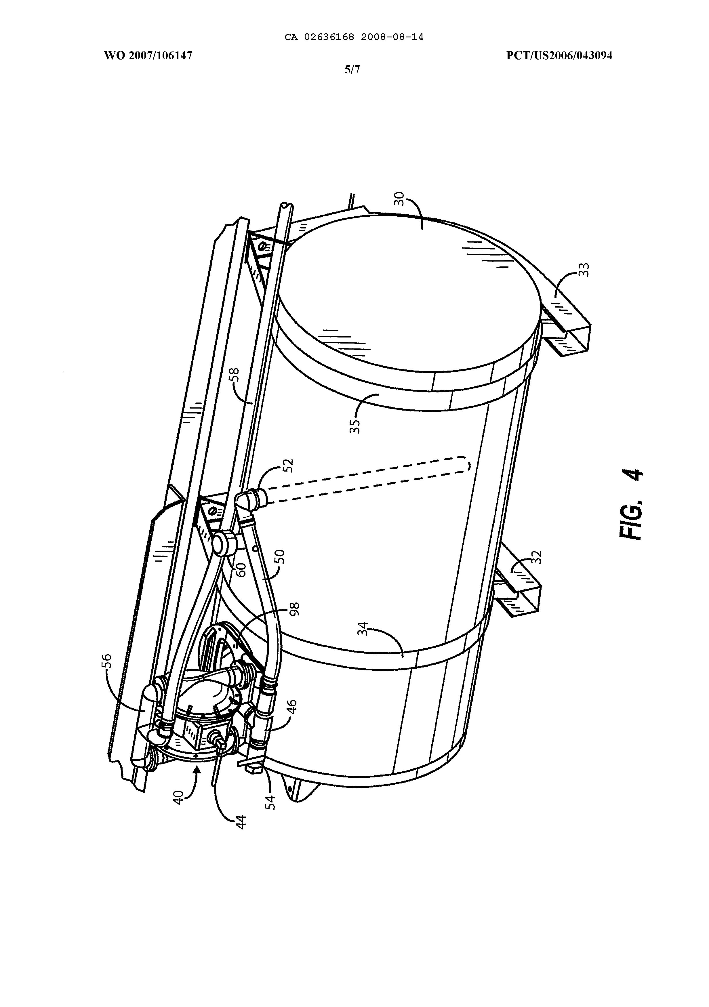
Another embodiment is depicted in Figure 4 in which the air-operated diaphragm pump is mounted on the fluid supply tank itself. The pump is fixed to a mounting plate 90 which is mounted to the upper surface of the tank 30. This embodiment also includes a water feed line which accesses the tank 30 from the top at 52 and which also preferably uses a bottom draw standpipe system.
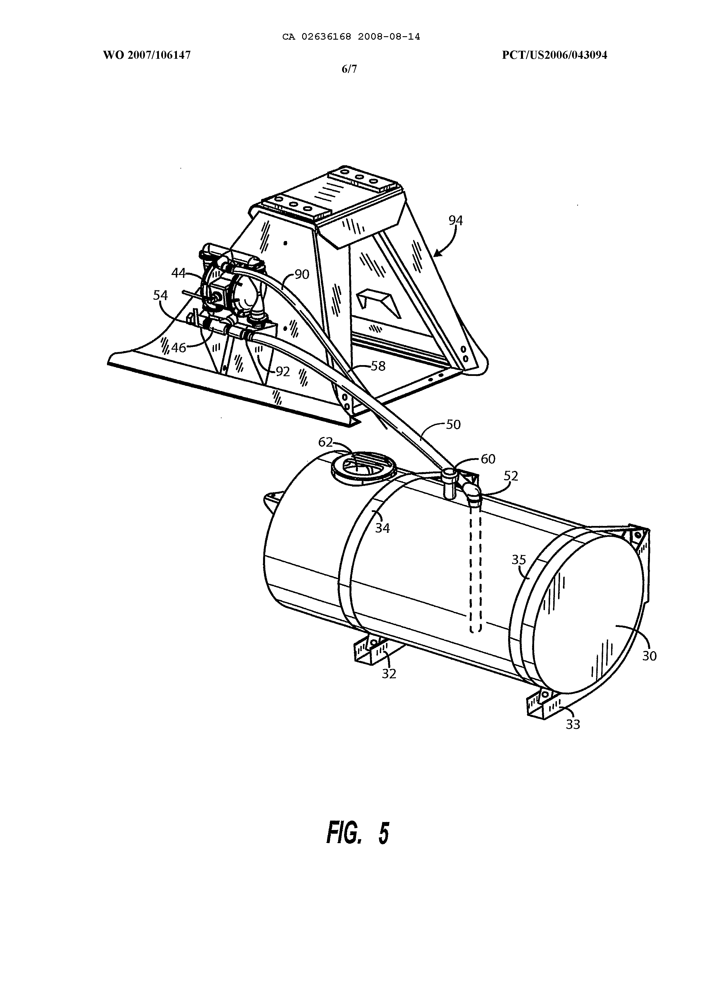
Figure 5 depicts yet another embodiment of an auxiliary fluid supply system in accordance with the invention in which the air-operated diaphragm pump 40 is mounted to the side of the fluid supply or water tank The pump is mounted on a bracket having a platform 90 and side members 92. The bracket is attached to a stable mounting stand structure 94 which, in turn, is mounted on a truck alongside tank 30 in any convenient location in a well known manner. Connections between the tank and pump and the pump include top mounted water feed line 50 and discharge hose 58. A drain valve 54 is also shown.
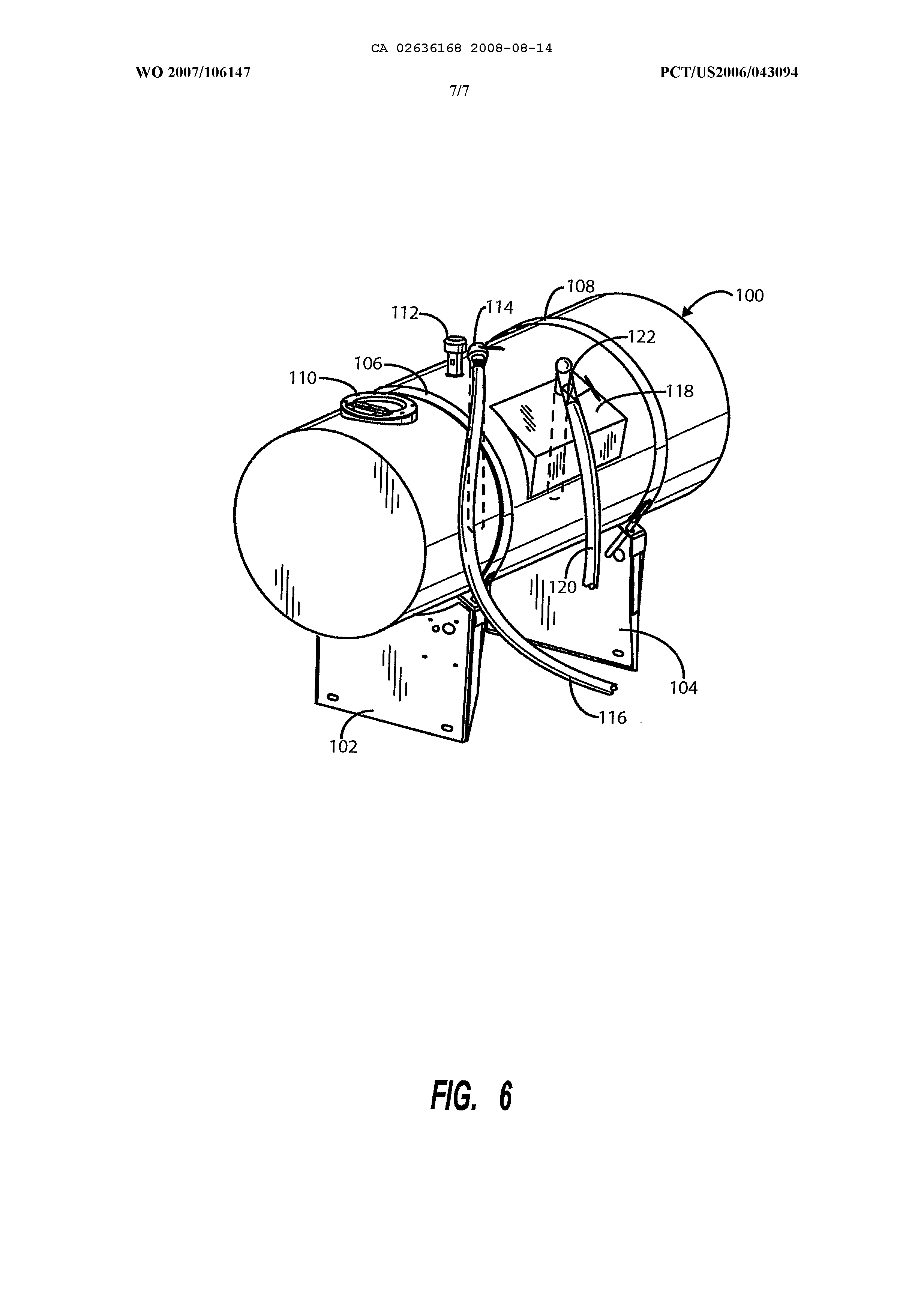
Figure 6 depicts an alternative embodiment of a water supply tank at i00 which is carried by a pair of spaced pedestals 102 and 104 and heavy attaching straps 106 and 108. A fill opening is shown at ii0 and a breather vent at 112. A top discharge, bottom draw connection is shown at 114 with outlet hose 116. The tank i00 further carries a smaller reservoir 118 WO 2007/106147 CA 02636168 2008-08-14 PCT/US2006/043094 containing additive material to be blended into the water supplied from the main auxiliary water supply tank i00 using supply hose 120 suitably valved at 122, which can be manifolded with supply hose 116 at the pump input or other conventional mixer system in a well known manner.
In operation, with a supply of water or other desirable fluid in the tank 30, the conventional output control valves (not shown) are opened in accordance with the use of the system and the diaphragm pump 40 is supplied with high pressure air, generally about i00 psig. The diaphragm pump 40 is operated to provide intake suction and pressurized fluid in the discharge line. When the desired amount of water is supplied for the desired use, the control valves in the pump discharge hose 58 and the drain/input valve 54 is opened. This allows water in the line to drain from the pump and also allows the pump to pump air through the system thereby purging out all the lines. This is particularly advantageous to avoid freezing of the system in cold weather.
This invention has been described herein in considerable detail in order to comply with the patent statutes and to provide those skilled in the art with the information needed to apply the novel principles and to construct and use embodiments of the example as required.
However, it is to be understood that the invention can be carried out by specifically different devices and that various modifications can be accomplished without departing from the scope of the invention itself.
What is claimed is:
CA 02636168 2008-08-14 WO 2007/106147 PCT/US2006/043094 A self-purging auxiliary fluid supply system for supplying washout or makeup water or other fluids under pressure to a truck-mounted concrete mixing/dispensing drum is disclosed. The system includes a truck-mounted fluid reservoir for containing a quantity of fluid connected to supply fluid to an air-operated diaphragm pump connected to supply auxiliary fluid from the fluid reservoir under pressure to a discharge assembly. The pump further provides an integral purge system for displacing fluid in the fluid supply system after use. I. A self-purging auxiliary fluid supply system for supplying washout or makeup water or other f1 uids under pressure to a truck-mounted concrete mixing/dispensing drum, said system comprising:
(a) a truck-mounted fluid reservoir for containing a quantity of fluid, said reservoir being connected to supply fluid to a pump assembly; and (b) an air-operated pump apparatus for supplying auxiliary fluid from said fluid reservoir under pressure to a discharge assembly associated with the operation of said concrete mixing drum, said pump having an intake assembly connected to receive fluid from said reservoir and said pump further providing air to an integral purge system for displacing fluid in said fluid supply system after use wherein said pump is adapted to be connected to a source of pressurized air for operating said pump.
A fluid supply system as in claim i further comprising a drain valve in said intake line for draining said intake assembly and acting as an intake valve for purge air. 3. A fluid supply system as in claim I wherein said pumping apparatus is a diaphragm pump. 4. A fluid supply system as in clam 1 wherein said fluid source is a top-discharsSng, bottom-draw tank and said pump is mounted on said tank. 5. A fluid supply system s in claim i wherein said fluid source is a bottom-draw tank and said pump is mounted apart from said tank. 6. A fluid supply system as in claim I wherein AMENDED SHEET (ARTICLE 19) CA 02636168 2008-08-14 WO 2007/106147 PCT/US2006/043094 said fluid source is a top-discharging, bottom-draw tank and.said pump is mounted apart from said tank. 7. A fluid supply system as in claim 1 wherein said intake assemble is connected to a plurality of fluid sources. 8. A transit, Concrete mixing vehicle for receiving concrete ingredients, mixing and dispensing concrete comprising:
(a) an inclined revolving concrete mixing drum carried on a vehicle chassis; (b) a self-purging auxiliary fluid supply system for supplying washout or makeup water optionally including other additives under pressure to said concrete mixing drum, said system comprising:
(i) a truck-mounted fluíd reservoir for containing quantity of fluid, said reservoir being connected to supply fluid to a pump assembly; and ( 2) an air-operated pump apparatus for supplying auxiliary fluid from said fluid reservoir under pressure to a discharge assembly as needed associated with the operation of said concrete mixing drum, said pump having an intake assembly connected to receive fluid from said reservoir and said pump further providing an integral purge system for displacing fluid in saíd fluid supply system after use wherein said pump is adapted to be connected to a source of pressurized air for operating said pump. 9. A fluid supply system as in claim 8 wherein said fluid source is a bottom-feeding tank and said pump Il AMENDED SHEET (ARTICLE 19) CA 02636168 2008-08-14 WO 2007/106147 PCT/US2006/043094 is mounted apart from said tank, i0. A fluid supply system as in claim 8 wherein said intake assembly is connected to a plurality of fluid sources.
AMENDED SHEET (ARTICLE 19)