DEVICE FOR FEEDING A PALLET WITH PAPIERSTAPELN.
The available invention concerns a device for feeding a pallet also from loose sheets bestehendea Papierstapeln, which are to be set off on the pallet up to a desired height nebenund/or one above the other. The Papierstapel can be up-in-and-flown for example to newspapers, magazines etc. be existed, the loose and be shipped to these closely lying on top of each other Anordlo nung i pile form on a pallet sollen.
Shipping reader Papierstapel on a pallet was implemented so far by hand or with the help of complicated and expensive machines, whereby in the latter case the entire pallet had to be driven to the different bearings of the Papierstapel, until the pallet was filled. It is as well known very difficult to handle a loose Papierstapel in such a way when shipping that the paper sheets do not slip; for this reason it is usual to coat the individual Papierstapel with foil or before shipping on the pallet too binden.
It is the task of the available invention to suggest such a device by which safe setting off and the accurate pile formation are ensured when shipping Papierstapeln on pallets, whereby the disadvantages admitted at present machines and procedures to that are repaired sollen.
Dea the subject of the invention screen end device is defined in the independent patent claim 1. Remark examples result from the dependent Patentansprüchen.
Owing to this invention with the suggested device the task posed is not only solved, but the device is outer ground electrodes very simply and cheap to manufacture. Each individual Papierstapel is held for a belt conveyor after the decrease of a promoter, for example, with firm grasp and the risk of mutual slipping of the newspapers is completely excluded. Also at this moment setting the pile off the newspapers maintain their mutual situation with security, since the pressing plate is pushed downward faster than the pile falling downward and thus slipping of the newspapers is not possible. When removing the grip arm the pressing plate is pressed against the top side of the pile, until the piston rod achieved its extreme end position, in which (? by the pile one moves away more ripely sufficient upward: so that a collision between grip arms and PapierstapeI is not possible. The pressing plate moves then into its completely withdrawn end position. Under the pressure of the pressing plate, which presses the pile against the carrying bars, air from the newspaper pile is herausgedrüekt; furthermore from a larger friction which likewise for the co-operation of the newspaper pile fuel element, results! carries. Since the robot is programmable, accurate ways between the promoter and the pallet can be prescribed for the movement of the newspaper piles, without the pallet must be moved. Since the pallet during loading err peace finds, large savings kind space requirement and workers can made werden.
A remark example of the Effindungsgegenstandes becomes following on the basis the beliegenden design beschrieben.
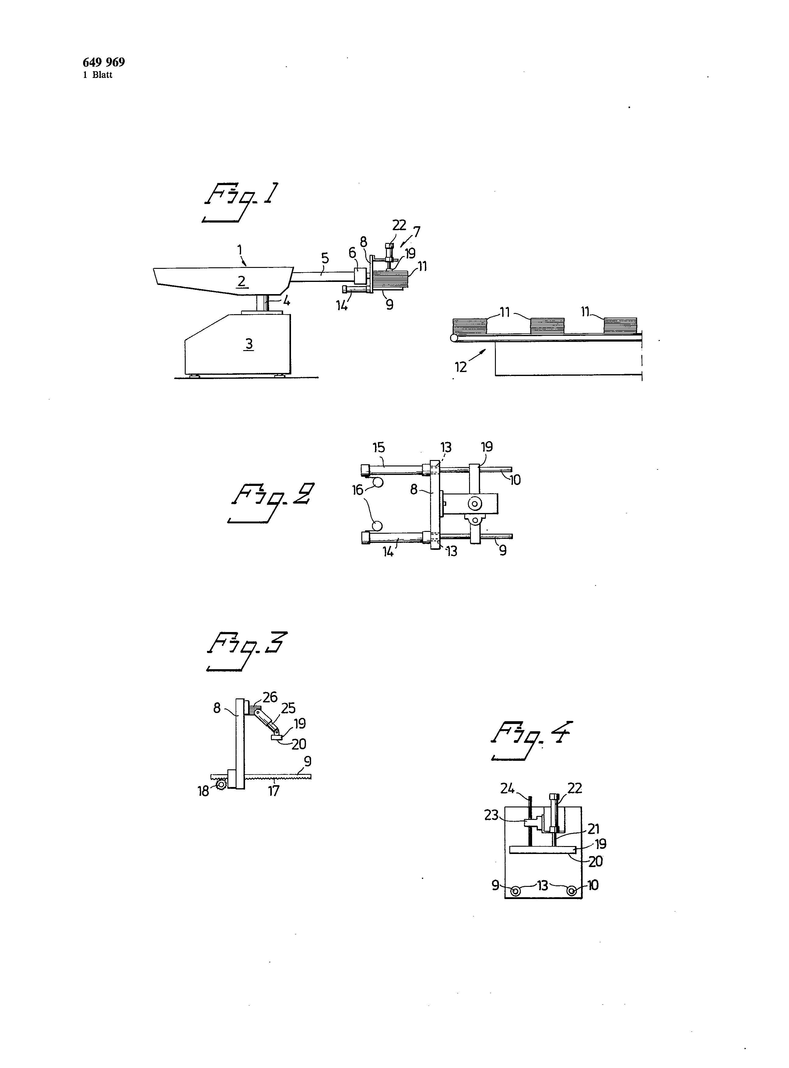
Fig. t is a schematic side view of such a device, Fig. a plan view shows 2 to a preferential execution form of the grip arm, Fig in increased representation. a further execution form of the grip arm and Fig illustrates 3 in increased side view. 4 is a side view in Fig. 2 of represented grip arm, seen from the side, from which the Papierstapel decreasing wird.
In the design under forgave on insignificant details represented device exhibits a industrial robot 1, its tiltable, ardaebbarer and lowerable section 2 to the body 3 of the robot over a wave 4 fastens. An arm 5 is in such a way installed at the section 2 that it can be stretched and drawn in again. That well-known robots 1 is programmable actually over a commercial plant including a memory, whereby this entire plant on the design is not represented. In this way the gewiinschte movement can be programmed directly into the memory, whereby the bionic arm is also by hand operatable 5. At its free end the arm 5 provided with a lathe fixture 6 is, on which a grip arm 7 is installed. The grip arm 7 covers a support plate 8, to whose unterere end at least two carrying bars 9 and 10 are so arranged parallel and in the mutual distance that they can seize the Papierstapel brought by a promoter 12 into the work area of the arm. The promotion element of the promoter 12 can cover for example several volumes, which started in such a way the pile 11 that the carrying bars 9 and 10 under the pile 11 push themselves leave/>
The carrying bars 9 and 10 preferably consist of hardened and polished steel pins, so that the friction is kept small and those are not damaged the carrying bars of neighbouring paper sheets with withdrawing the carrying bars. Preferably the carrying bars 9 and 10 are stored by means of antifriction bearings, for example Kugellagem, in the support plate 8. In accordance with the Fig. 1, 2 and 4 exists the carrying bars of 9 and 10 cylinders 14 and 15, which fasten parallel to each other arranged and to the lower edge of the support plate, pneumatic from the piston rods, on that the lathe fixture 6 turned side, sind.
In their withdrawn end position the front edges of the carrying bars 9 and 10 are either fluehtend or something within concerning the front surface of the support plate 8, against soft a side of a pile 11 push away. Other, end position of the carrying bars expresses 9 and is regarding the format of the pile 11 regulierbar.
In order to permit the fast withdrawing of the carrying bars 9 and together with the file of the pile 11, are the bars with pneumatic Schnellventilin 16 ausgerüstet.
As itself from the variant in accordance with Fig. 3 results in, exhibit the carrying bars 9 and 10 teeth 17, which form racks thus on the lower surface of the carrying bars. The teeth 17 stand in interference with a propelled wave 18, those between the lathe fixture 6 and the support plate 8 arranged are and the carrying bars 9 and 10 between their appropriate end positions back and forth bewegt.
A pressing plate 19 is arranged above the carrying bars 9 and in the distance from the upper section of the support plate 8 that it can be induced rectangular to the carrying bars 9 and 10. The pressing plate 19 is provided with a friction plate 20, so that it does not slide on the top side of the Papierstapels 11. Air in the pile 11 becomes by the Anpressdruek of the pressing plate 19 herausgedrückt.
With in Fig. 1, 2 and 4 represented execution form the pressing plate is operated by a piston rod 21, which cooperates with vertically adjustable pneumatic 3,649,969 cylinders 22. The cylinder is fastened to the upper section of the support plate 8 and the distance between the piston rod 21 and the support plate 8 is adjustable, with which the changing format can be considered to carrying NOC the Papierstapel. The distance of the piston rod axle from the support plate 8 should have preferably for instance z/5 of the appropriate pile dimension, which rectangular to the support plate 8 measured wird.
The pressing plate 19 fell independently of the piston rod lo 21 by a guide rod 24 and/or led, which is sliding stored in a guide sleeve 23. The Fühnmgshülse 23 stands with the support of the cylinder 22 in Wirkungsverbindung.
Like the variant in accordance with Fig. the pressing plate 19 anch swivelling at a telescopic Schwingarm 25 shows, can 3 arranged be, which is turningrigidly to a rotation engine 26 fastened. This rotation engine 26 is on the upper section of the Abstfitzplatte 8 and serves thus for the creation of the contact pressure at the Papierstapel 11.
After the robot with the desired Bewegungscharakteñstik was programmed, the pallet load device works as follows: The grip arm 7 swings 11, more softly on the promoter 12 its extreme situation into its operating position before the Papierstapel takes, so that 2s the taken off carrying bars 9 and 10 rise up under the pile. The final section of the promoter 12 and its promotion element are in such a way formed that the bars 9 and 10 under the pile 11 can arrive. The grip arm 7 is moved in such a way against the pile 11 that the Abstiitzplatte ges0 hits towards her turned the surface of the pile. The bionic arm 5 then upward moved see, while the pressing plate 29 presses the Papierstapel 11 against the carrying bars 9 and 10. Now the arm 5 in its swings programmed position above the file place of the 3s of pile on the pallet, on which it lowers the pile to scarce above the placing surface. The carrying bars 9 and are very rapidly pulled away, so that the pile falls downward; the pressing plate wírd here still faster than the falling pile moves downward, so that it squeezes the pile together further and prevents a slipping of the newspapers. Since the pressing plate exhibits a long stroke way, relatively large level differences can be bridged with the placing of the pile 11. The arm 5 moves then with the grip arm 7 upward and 4s the pressing plate 19 releases its pressure on the pile 11, if it is in its extremely taken off end position, whereby the Papierstapel turned off now is not disturbed when taking the grip arm off. If the pile 11 is turned off on the pallet, both the highest is completely intact and then the lowest paper sheet. The pressing plate 19 is only then brought withdrawn end position into its highest, if the grip arm 7 in the sufficient distance from the turned off Papierstapeln 11 is. The arm 5 with the grip arm 7 induces itself then zus5 back to the promoter 12, to take up around whom next pile 11 and this cycle as many times repeated, when it was programmed in the memory, i.e. until the pallet up to the desired height is loaded. When unloading the piles are turned, so that the paper sheets come to lie mnstergerecht one on the other. The signals for the functions of the pressing plate and the carrying bars are likewise in the memory pre-programmed, whereby the device absolutely automatically, i.e. without any manual participation of humans, work kann.
v I sheet designs 649,969 1 sheet 1 i 1 1 l 16 13 19 IL 24 _ 22 2321 I I II ç i According to the invention, a machine is disclosed for handling and preferably loading loose signature packs onto a pallet. In a preferred embodiment, the machine comprises an industrial robot known per se, which has an arm movable in all planes. This arm is provided with a rotation device on which is mounted a gripping device incuding at least two horizontal, reciprocally movable carrying rods co-acting with a support plate and at least one vertical pressure plate movable toward and away from the carrying rods for gripping and conveying a pack of loose signatures from a conveyor and depositing them in a programmed pattern for building a load on a pallet. 1. A machine for loading loose signature packs as onto a pallet in a predetermined pattern, said machine comprising: horizontally extending arm means for carrying unbanded signature packs from a predetermined pick-up point to a deposit point laterally displaced from said pick-up point, for deposit on a pallet, said arm means having a free end; gripping means rotatably disposed at said free end of said arm means for rotation about an axis extending lengthwise of said arm means; said gripping means comprising carrying means for carrying a pack of signatures, said carrying means being movable relative to said arm means between a retracted position in which said carrying means is unable to carry a load and an extended position in which said carrying means is available to carry a load of signatures; said carrying means being sufficiently quickly and suddenly movable from said extended to said retracted position to enable said carrying means to be suddenly withdrawn from under a load supported by it, without imparting to such load motion in the direction parallel to the retraction of said carrying means, and pressure means for exerting pressure on a load of signatures carried by said carrying means for pressing such signatures against said carrying means, and for pushing such signatures strongly downward onto a pallet when said arm means has brought such load of signatures to said deposit position and after said carrier means has been suddenly retracted to release such pack. 2. The machine of claim 1, wherein said carrying means comprises at least two parallel rods. 3. The machine of claim 2, wherein said parallel rods are movable axially between said retracted and said extended positions. 4. The machine of claim 2, wherein said rods are made of a low-friction material. 5. The machine of claim 2, wherein said carrying means comprises a respective air cylinder for each said rod, said rods being retractable into their respective said air cylinders for movement to said retracted position. 6. The machine of claim 5, further comprising a support plate disposed at said free end of said arm means and perpendicular to the direction of movement of said carrier means; said support plate having holes formed therein; said air cylinders extending from said support plate in one direction and said rods when in said extended position extending in the opposite direction from said support plate and passing through said holes therein. 7. The machine of claim 6, wherein said rods when in said retracted position are approximately flush with the surface of said support plate. 8. The machine of claim 2, wherein each said rod has one side for receiving a load of signatures and has another side opposite said one side formed with teeth; and further comprising gear means engaging said teeth of said rods and means for driving and gear means to drive said rods between said retracted and said extended positions. 9. The machine of claim 1, further comprising rotation means connecting said free end of said arm means and said gripping means to each other rotatably. 10. The machine of claim 1, wherein said gripping means further comprises a support plate disposed perpendicular to the direction of movement of said carrier means between said extended and said retracted position. 11. The machine of claim 10, further comprising rotation means connecting said gripping means rotatably to said free end of said arm means, said support plate being secured to said rotation means. 12. The machine of claim 1, wherein said pressure means comprises a pressure plate for pressing a load. 13. The machine of claim 12, wherein said pressure means further comprises a piston and an air cylinder for applying pressure via said pressure plate to a load. 14. The machine of claim 5, wherein each said air cylinder for said rods is provided with valve means for rapidly bleeding air from said air cylinder. 15. The machine of claim 12, wherein said pressure means further comprises a telescopic arm having said pressure plate secured to one end thereof, and means for powering said telescopic arm for applying pressure via said pressure plate to a load. 16. The machine of claim 1, wherein said carrier means is adjustable for varying said extended position thereof. 17. The machine of claim 16, wherein said pressure means is adjustable for varying the point at which it applies pressure to a load borne by said carrying means. 18. The machine of claim 1, wherein said pressure means is for applying pressure to a load borne by said carrier means at a point approximately two-fifths of the way from said free end of said carrier means when said carrier means is in said extended position.