SUPPORTER FOR TRUCK.
The invention concerns a supporter for truck, which is trained as multi-oh supporters with a trailer for six-wheelers, whose front axle exhibits a bogie and a king pin, whereby the Deichselstützen Zugeinrichtnng rigidly lockable ist.
The well-known Mehraehsanhänger is not intended for it, during the normal enterprise individual axles auszuwechseln.
The same is valid from the well-known trailers for six-wheelers, which exhibit a quadrant for example in the saddle support place over the king pins and directly over the ball race of the bogie of the axle and/or the front axle of a Doppelaehsaggregates a rear quadrant, over which the steering of the axles effected. There are Sattelanhänger.<br also with one axle/>
During different one steering system for trailers for six-wheelers a crank gear is inserted according to kind of a sehwingenden crank slot, with which the steering bar is telescope-like extendable. The ãussere telescope pipe is rigidly fastened to the bogie, while the internal telescope pipe with its front end on a crankpin of the Seilseheibe is articulated stored. In this way one knows the steering angle of the axle steuern.
With one this well-known Lenkvorriehtungen lür trailers for six-wheelers is formed the guidance connection to the front quadrant over the king pins of the swivelling saddle plate, which is firmly connected with the quadrant. It is particularly favourable that the rope between the quadrants is arranged over the cross. Thereby the advantage develops that the mechanical guidance connection with the telescope-like extendable steering bar, mentioned above, can be void completely (DEGM 8020446).
The invention is the basis the Aut abe, the supporter of the Eingaugs mentioned kind to train in such a way that he and/or parts the same substantially more versatile; as so far usable sind.
The solution of this task by the invention is into the kennze chnenden characteristics of the requirement 1 definiert.
Thus the front axle is independent of the multi-oh supporter by disengaging with a trailer for six-wheelers verwendbar.
One can also say that the Vorderaehse for see alone as trailers for six-wheelers with one axle be erwcndet can. Such a possibility of combination is desired e.g. in countries, in which the Gesamtgewiehtshegrenznng for double trains is limited on 28 t e.g., because thereby an optimal Fahrzeugausnutznng makes possible wird.
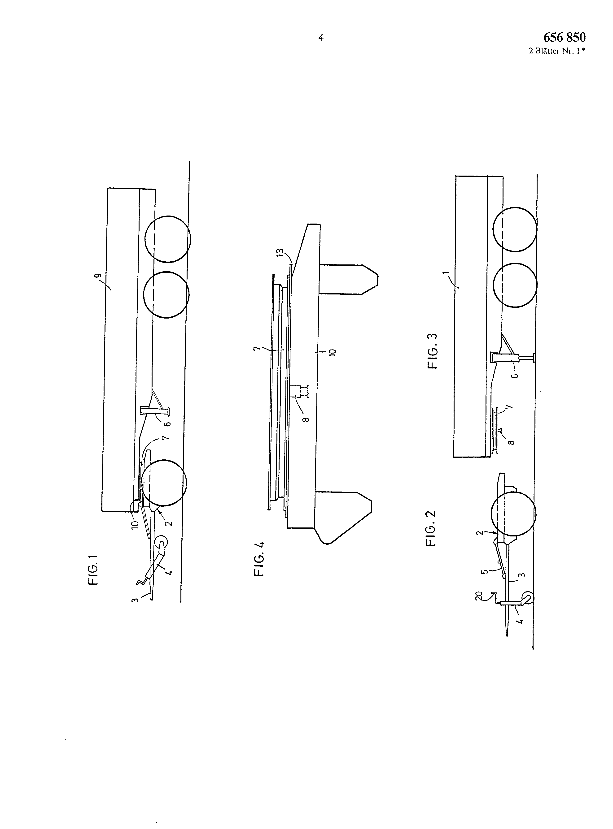
Further advantages and details of the invention devoted see from the following description of a Ausführangsbeispiels under reference to the design. In this show:
Fig. 1 a Mehráehsanhänger in installed driving condition:
Fig. 2 the deinontierten front cars after Fig. 1 fur itself alone; Fig. 3 the turned off remainder vehicle without the front car; Fig. 4 an increased side view on a part of the front car in the installed condition with the ball race, whereby the remainder of the vehicle is omitted:
Fig. 5 a Drauf view on the baseplate fiir see alone in its installation position on the front car:
Fig. 6 a cut after the line A-B of the Fig. 5 and Fig. 7 a strongly increased cut by a part of the front car with installed baseplate, Fig. l shows a multi-oh supporter with three axles. Is in front a rigidly lockable pole Stfitzen Zugeinrichtung 3 with a Stfitzrad folded upward 4 watch. In accordance with the invention the front axle aggregate is designed as front car 2, as is still described later. Further right one does not see a drawn in saddle bracket 6, exactly behind it is a further, visible Sattelstfitze of this kind arranged. In all other respects this Mehraehsanhänger 9 does not differ from those conventional design, so that it are also not continued to describe muss.
Fig. 2 shows the front car 2 in dismantled condition for itself alone. This concerns the same front car 2 after Fig. 1, which was only dismantled, as the support 6 was driven out downward, woraufl into late nuts still which can be described the 17 was solved, the Stfitzrad driven downward and the whole pulled out forward. For this even a Zngfahrzeug is not necessary. One can also by hand forward drive out and install the front car later also again by hand, without a course [hhrzeug.
Over the gange wheel 4 one sees a crank handle 20, under it the Zugeinriehtung 3, at which the Deichselstütze 5 is linked to a mounting plate of the front car 2 to the right above. The details of a such pole support course mechanism are the specialist well-known and must from there not in detail besehrieben in such a way werden.
Fig. 4 shows only the Drehkrlnz 7 with the bogie installed to it I 0 of the front car. The baseplate 13 forms here a component of the ball race 7 or is constantly fastened with this. In the center one sees the king pin 8, which is arranged in the center of the bogie 10, here with interrupted lines like one also the Fig. 5 infers kann.
The Fig. a Draufsieht shows 5, with that the ball race 7 contrary to the Fig. 4 of the better clarity because of let go away ist.
The bogie! 0 shows first on the left of above and down two Ansehlageeken 14 A and 14 b, which are firmly connected with the bogie 10. To these the baseplate fastens 13 with its Einlaufkanten 18 A, 18 b, which are pushed for 12 C in this representation also under the projections/leads of the stop angles 12 A, directed inward, I2 b. The Grnndplatte 1 3 is thus fixed by the attacks 12 in its situation both after” orn in driving direction and after the two sides. In the proximity of the stop angle 12 A in driving direction furthermore the two mounting plates 15 A, 1 5b two similar mounting plates 15 C and 15 D further for the tightening screws 16 at the Drehgestelt, are arranged in front are at the rear edge of the bogie angebracht.
In the center the king pin 8 is cut represented. It sits in a Einlanfschlitz 21 of the bogie 2, which extends to the rear conical in driving direction, where the two conical bevels 11 A, 11 b with interrupted Linicn dargestcllt sind.
Furthermore at the four corners of the bogie 10 are the feather/spring thrust the 22, 23, 24 and 25 in well-known way for the admission of the feathers/springs angeordnet.
Fig. a detail with the cut A-B of the Fig shows 6. 5. Here one sees clear that the baseplate 13 under the Anschlagwiukel 12 A is pushed more ñber the bogie 10, to which the Einlaufkante 19 at the angle 12 A is attached. Beyond that the Ausscnkante of the baseplate 13 in its upper range rounded off with the reference symbol 26 is, so that she fastens 12 A on the one hand with large surface at the stop angle, on the other hand in addition, easily under the bevel 19 led wird.
The Fig. 7 a cut by the installed front car 2 with the bogie 10. sees here one points down, D ss at the bogie 10 an eye 27 to the admission of the axis of rotation 28 of the Klappschraube 16 is arranged. This is shown right with dash-dotted lines in its near-swivelled situation of 16 A, wãhrend it in the fully taken off situation in one of the mounting plates sits, those in Fig. 5 described is. With taken off lines also the wearing part 29 and the mother 17 are represented, by those the baseplate 13 with the DrehgesteI1 10 bolted ist.
For the assembly from the dismantled situation after the Fig. the front car 2 is pushed for 2 and 3 to the right under the vehicle 1. Here the mentioned centring takes place via the king pin 8, that at the bevels 11 A, 11 b into the slot 21 led wird.
Also the Einlaufl anteu 18 A, 18 b serves this purpose, whereby they are led first afterwards at one the stop angle 12 b, 12 C and 656,850 at the attack corners 14 A, 14 b, until to the assembly position the Fig. 5 is reached. In this situation the baseplate is completely in their situation fixed, now can the KIappschrauben carrion of their situation of 16 A into the situation of 16 brought to 13 of the ball race 7 by the stop angles 12 and the wearing parts 29 as well as the nuts! 7 to be applied and tightened. By all four mounting plates is manufactured 15 A, 15 b, 15 C and 15 D one kraftund formschlfissige connection between the parts, so that slipping is impossible. For the additional protection lo then dic still mentioned upper inward arranged projections/leads of the stop angles serve 12, those when tearing all four screws a loosening of the baseplate 13 from the bogie verhindern.
Afterwards the Stfitzrad 4 can know lifted up and the saddle brackets 6 to be drawn in, according to which the vehicle ist.
The disassembly carries out itself, like already mentioned, in reverse order. After the release and hinging the screws 16 into its position 16 A away the front car 2 with lowered saddle bracket 6 leaves itself easily forward under the vehicle herausfahren.
There is now the possibility of supplying the front car 2 for itself alone any different intended purpose e.g.
as Sattelanhänger.<br with one axle/>
The invention is not limited to the represented execution form, viclmchr is possible for modifications in the context of the general invention thought, which consists of the fact that by disengaging as front car the combination with a trailer for six-wheelers makes possible for the front axle ist.
Thus alternatively either the represented can after multi-oh supporter the Fig. I to be formed or a well-known trailer for six-wheelers by means of the front car according to invention 2nd Dcm specialist, not represented in the design, is possible it to provide numerous Abwandlungcn of the represented execution form without the erwfihnten Erfindungsgedanken too verlassen.
tt 2 sheets designs of 656,850 2 pages No. 1 * o D ti_ ù4 " c5 I.r.
, ì: O ¢v3 I.t_ ç, I 11 I i i 'oo ¢xl C) ¢, q The invention relates to a trailer for a lorry, which is designed as a multiple-axle trailer, the front axle of which has a pivoted bogie and a kingpin, the drawbar-support and towing device being capable of being rigidly locked. In this case, the invention is based on the object of designing the trailer in such a manner that the front axle can be used with a semitrailer, independently of the multiple-axle trailer, by uncoupling therefrom. The solution consists in that the trailer is provided with semitrailer supports in the region of its front axle and in that the front axle, with its pivoted bogie as the front carriage, can be detached from the turntable ring, can be operated as an independent unit and can optionally also be coupled to a semitrailer of known design. By this means, the front axle can be used on its own as a single-axle semitrailer. This is desirable for example in countries in which the total weight limitation for articulated road trains is limited for example to 28 t. The invention permits optimum utilisation of the vehicle. <IMAGE>