Electrochemical system for measuring cells of e.g. fuel cells, has buffer unit provided between amplifier and control unit and saving voltage representative of potential difference in simultaneous manner
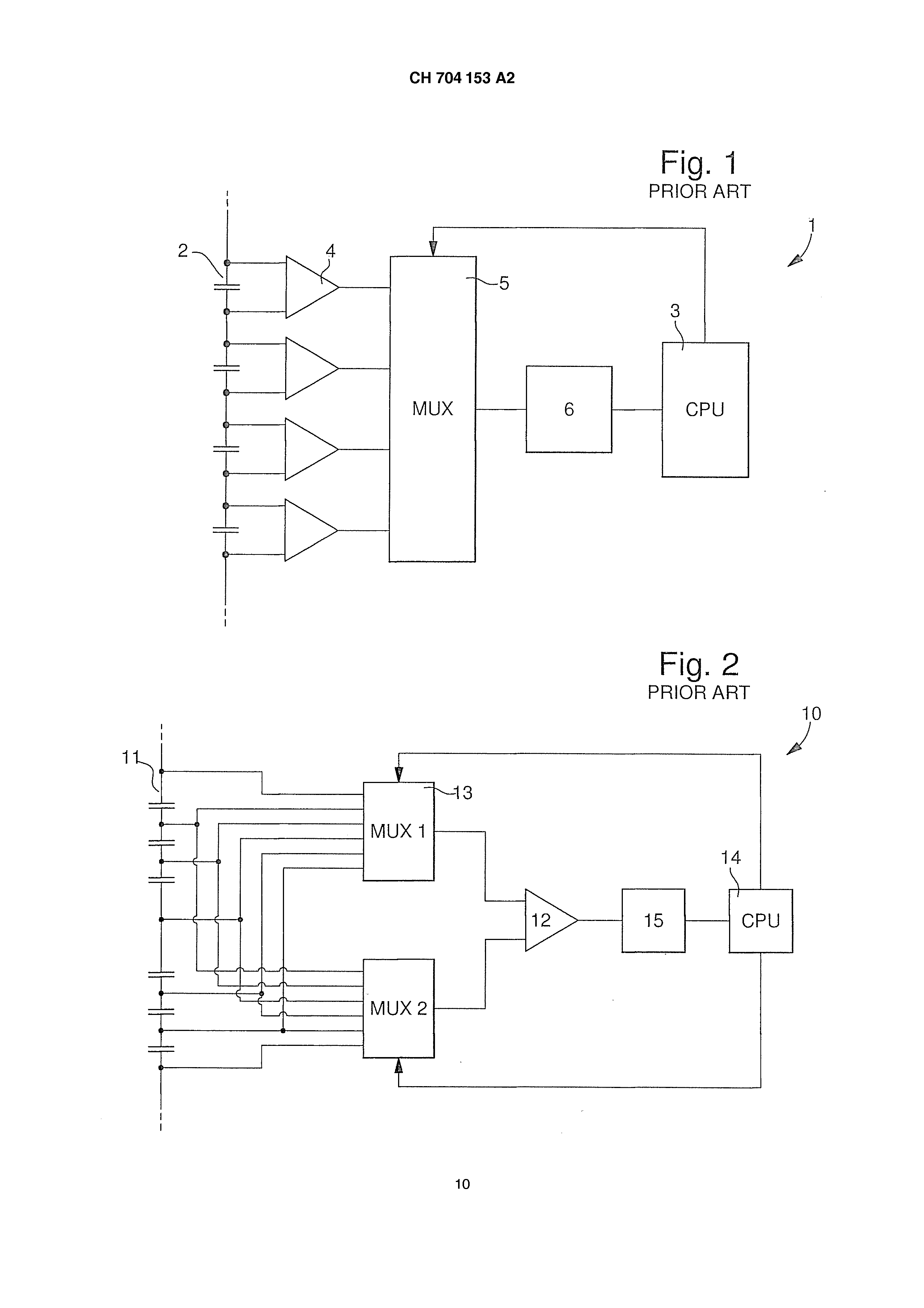
HM 704,153 a2 specification la an electrochemical system. The system includes a stack of electrochemical blocks connected in series. The system is controlled by a control circuit and comprises a plurality of differential amplifiers each connected by two input terminals of an electrochemical block to provide a voltage representative of the potential difference present between terminals of said electrochemical block. Each representative voltage is sent to a control unit arranged to convert the representative voltage into a digital value transmitted to the control circuit. Technological background on known assemblies electrochemical blocks connected in series (often called stacks). The electrochemical blocks thus assembled can be constituted for example by battery cells, or by fuel cells. A fuel cell is an electrochemical device provided for converting chemical energy directly into electrical energy. For example, a type of fuel cell included an anode and a cathode between which is arranged a membrane proton-exchanged often called polymer electrolyte membrane. This membrane allows only passing the protons between the anode and the cathode of the fuel cell. At the anode, diatomic hydrogen undergoes reaction produce ions and will pass through the polymer electrolyte membrane. the electrons produced by this reaction are adjoined to the cathode through an external circuit to the fuel cell, thereby generating an electric current. du is that only a single fuel cell does, in general, that a low voltage (about 1 volts), assembling the fuel cells often in series to form stacks of fuel cells capable of producing a higher voltage which is the addition of voltages of each cell. A disadvantage of the fuel cells is that it is not sufficient for the stopping of the disconnect. Indeed, if the current output from a fuel cell is suddenly reduced to zero, the fuel cells that make up the stack not received to eliminate the electrochemical energy they produce, and the voltage across the different cells rise to the point of causing an accelerated degradation of the polymer membrane and catalysts that are associated with it. It is not sufficient instead of shutting off fuel and oxidant for stopping a fuel cell. In this case, indeed, the amount of fuel and oxidizer enclosed within the stack is sufficient to maintain the reaction for a considerable time. In the case of a fuel cell using hydrogen as fuel and pure oxygen as oxidant, the [...] even take several hours and stops. il is therefore advantageous for open-systems to electrochemical blocks, such as fuel cells, measuring devices for monitoring the voltage produced by each cell to detect any variation when the system is in operation to electrochemical blocks [...] constant or ' it is in the resting phase. il is known measuring devices called asynchronous in two forms. in the first form illustrated in fig. 1, the system 1 to electrochemical blocks comprises a plurality of differential amplifiers each connected by 4 two input terminals of an electrochemical block 2 to provide a voltage representative of the potential difference between the terminals of said electrochemical block 2.4 differential amplifiers are connected, output, to a multiplexer 5 whose output is connected to an analog to digital converter 6.. the multiplexer 5 is then operated to sequentially select each differential amplifier 4 so that the voltage representative of the potential difference present between the terminals of said electrochemical block 2 to which it is connected, can be sent to the analog to digital converter thereof 6. then digitizes said voltage and sends it to a processor or CPU 3 that retrieves all voltages representative then digitized to interpret them. in the second form shown in Figure. 2, the system 10 comprises a first electrochemical block and a second mux1 mux2 multiplexer 13, the positive terminal of each block 11 is connected to the input of the first multiplexer 13 and the negative terminal of each block 11 is connected to the input of the second multiplexer. The output of each multiplexer 13 is connected to an input of a differential amplifier 12. measuring the voltage representative of the potential difference between the terminals of an electrochemical block 11 is performed by selecting, through the first and second multiplexers 13, the potentials corresponding to said electrochemical block 11. These potentials are supplied to the differential amplifier 12 to provide said voltage representative of the potential difference. Measuring the voltage representative of the potential difference between the terminals of the electrochemical block next 11 is then sent to a digital analog converter 15. It then digitizes said voltage and sends it to a processor or CPU 14 that retrieves all voltages representative digitized for then interpret. or, the disadvantage of these two forms is that they are asynchronous. Indeed, the method used in either form measurements are taken one after the other. Therefore, in the case of a stack of electrochemical blocks comprising one hundred electrochemical blocks, necessarily involves measuring the voltage of the hundred electrochemical blocks so as to have the voltage representative of all blocks of the stack. Accordingly, before it can again be measuring the voltage of the first electrochemical block, requires the measurement of the voltage HM 704,153 a2 representative for the set " of electrochemical blocks. Also there is a time interval between two measurements too large voltage representative of the same electrochemical block. de more, this method induces a time offset between two voltage measurements of two adjacent electrochemical blocks. This implies that it is not possible to have, at a determined time, the state of all electrochemical blocks since the measurement of the voltage representative of two adjacent electrochemical blocks is not performed when the blocks are in the same state electrochemical, a time offset being arisen. There is thus a risk that a variation in voltage of one of the electrochemical blocks is not detected and cause damage of the system to electrochemical blocks. And even [...] ' a problem is detected, there is not any means know which electrochemical block is defective since the voltage drop across them may vary according to the operation conditions. Summarizing the invention un aim of the present invention is to provide an electrochemical system comprising a stack of electrochemical blocks wherein the measurements of a voltage representing the potential difference present between the terminals of the electrochemical blocks are reliable and instantaneous and enabling simple and efficient detection of trouble at one or more blocks. a this purpose, the invention concerns an electrochemical system being characterized in that it comprises, between each differential amplifier and the control unit, a buffer means controlled by the control circuit, the buffer means being capable of saving the voltage representative of the potential difference between the terminals of the present electrochemical block to which it is connected, and that the backup voltage is performed simultaneously by the buffer means. un advantage of the present invention is to measure the voltage of each block simultaneously so as to obtain, at an instance in time, the voltages of all electrochemical blocks. After retrieving, at different times, the picture of the tension of any electrochemical blocks, the user can then compare these images representative of the stack of electrochemical blocks. It can then easily detect a problem due to a change in voltage of one or more electrochemical blocks but also easily detecting the one or more electrochemical blocks defective. advantageous embodiments of the electrochemical system according to the present invention are the subject of dependent claims. in a first advantageous embodiment, each buffer means comprises first switching means and second switching means connected in series between the amplifier to which the buffer means is connected and the control unit, each buffer means further comprising a capacitor whose input is connected to the connection point between the first and second switching means and thus the output is connected to a reference point. in a second advantageous embodiment, the set of second switching means is grouped in the form of a multiplexer whose input is connected to each first switching means a buffer means, the output of the multiplexer being connected to an between the control unit. in a third advantageous embodiment, that said stack of electrochemical blocks is subdivided into different groups comprising several electrochemical blocks each associated with a differential amplifier and buffer means, and a control unit connected to the output of the buffer means associated with each electrochemical blocks of the group, and each group has its own voltage reference in effect, electrochemical dividing blocks in groups of several electrochemical blocks reduces the potential difference between the blocks of the same series. In addition, each group having its own reference voltage, the potential difference between the different blocks of the same series and the reference voltage of the group of control associated with this series can be kept within a range compatible with ordinary semiconductor devices. in another advantageous embodiment, the voltage reference of each group is taken on one of the terminals of an electrochemical block belonging to said group. in another advantageous embodiment, the second switching means blocks belonging to the same group are grouped together in the form of a multiplexer whose input is connected to each first switching means a buffer means, the output of the multiplexer being connected to an input of the control unit of said group. in another advantageous embodiment, the control unit of each group is connected to the control circuit via the communication means. in another advantageous embodiment, the first switching means of each buffer means are in the form of a transistor driven by a control signal. in another advantageous embodiment, the second switching means of each buffer means are in the form of a transistor driven by a control signal. HM 704,153 a2 in another advantageous embodiment, the control signal of each transistor is sent by the control circuit. in another advantageous embodiment, the control signal of each transistor is sent by the control unit. in another advantageous embodiment, the control unit comprises at least one analog to digital conversion means arranged for digitizing the voltage value representative of the potential difference between the terminals of each present electrochemical block. in another advantageous embodiment, the control unit comprises a number of the analog digital conversion means equal to the number of buffers, each buffer means being connected to an analog to digital conversion means. in another advantageous embodiment, the control unit of each group includes at least one analog to digital conversion means arranged for digitizing the voltage value representative of the potential difference present between the terminals of each of said electrochemical block group. in another advantageous embodiment, the control unit of each group includes a number of the analog digital conversion equal to the number of buffer means of said group, each buffer means being connected to an analog to digital conversion means. de more, this division of electrochemical blocks in plural sets each associated with a control unit can be treated information faster. It is possible to perform analog-to-digital conversions in parallel. This means that each block group electrochemical digitizes, at the same time, the voltages representative of the potential difference between the terminals of the present electrochemical block each of said group. This allows then save time and, thus, a measurement pulse greater can be thought of offering improved monitoring. l'invention also relates to a method for managing the above-mentioned electrochemical system. The system further comprises, between each differential amplifier and the control unit, a buffer means controlled by the control circuit, said buffer means comprising a capacitor connected to its input, to the output of the differential amplifier by a first switching means and to the control unit by a second switch means and at its output, connected to the system ground. The system operates in a first so-called normal operating mode in which the first and second switching means is open and a second mode of operation said measurement wherein the following steps are performed: - close, simultaneously, the first switching means of each electrochemical block; and - save, in each capacitor, the voltage representative of the potential difference between the terminals of the present electrochemical block to which said capacitor is connected; and - open, simultaneously, the first switching means of each electrochemical block; and - processing the voltage values representative of the potential difference between the terminals of each present electrochemical block by transmitting it to the testing unit by action on the second switching means of each buffer means. in an advantageous embodiment, the step of processing the voltage values representative of the potential difference between the terminals of each present electrochemical block includes closing sequentially on the second switching means of each buffer means to transfer the value saving in each capacitor to the control unit. in another advantageous embodiment, said stack of electrochemical blocks (102) is subdivided into different groups comprising several electrochemical blocks each associated with a differential amplifier and buffer means, and a control unit connected to the output of the buffer means, each group having its own voltage reference and in that the steps of the second mode of operation are performed for each group sequentially. in another advantageous embodiment, the steps of the second mode of operation are performed, for each group, simultaneously. Brief description of the drawings goals, advantages and characteristics of the electrochemical system according to the present invention will accompany more readily apparent from the following detailed description of at least one embodiment of the invention given solely by way of non-limiting example and illustrated by the annexed drawings on which: the Figures 1 and 2 Figure 3 represent schematically the electrochemical system according to prior art; represents schematically the electrochemical system according to a first embodiment of the present invention; Figures 4 and the ch-704,153 a2 the fig.. 6 fig. 7 fig. 8 represent schematically the buffer means of the system according to the present invention; represents schematically a variant of the electrochemical system according to the first embodiment of the present invention; represents schematically the electrochemical system according to a second embodiment of the present invention; and represents schematically a variant of the electrochemical system according to the second embodiment of the present invention; detailed description of in the following description, all parts of a fuel cell known to a skilled worker in this technical field will be explained simplified. in Figure. 3, there is schematically represented an electrochemical system 100 according to the present invention associated with a fuel cell. The latter includes a multitude of electrochemical blocks 102 each having a negative pole and a positive pole serving as connection points. In the present example, each block 102 may be a single fuel cell 102 or more contiguous fuel cells. However, for simplifying, in following the description it is called indifferently of electrochemical cell or block 102 102 even though it is possible that a electrochemical block 102 is in fact formed of two cells 102 or more. The electrochemical blocks 102 are connected in series to form so-called a fuel cell. Each cell 102 provides a voltage value reaches about 1.2 volts which, for an example of a quarantine of series-connected cells, gives a total voltage of about 48 volt. The entire system is controlled by control circuit 104. in a first embodiment, the system includes a control unit 106 provided for communicating with a control circuit 104, said control unit 106 in the form of a microprocessor. The control unit 106 is powered by the supply of the electrochemical system 100. It communicates with the control circuit 104 via a means or communication system 108. The communication means 108 allows the central control circuit 104 send instructions to the control unit 106. It also leads to the control unit 106 to send to the control circuit 104 information on the status of the fuel cell 102. The communication means 108 can be a bus 110 in the form of a set of parallel electric wire. The bus 110 may use the protocol used SPI comprising 3 individual wires or any other protocol, such as for example 120 protocol. le electrochemical system 100 also includes measurement circuitry 112 which are each constituted by a differential amplifier 114 associated with a electrochemical block 102, as shown in Figure 3. these differential amplifiers 114 operate with voltages supplied by the power supply of the system. The differential amplifiers 114 have two inputs respectively connected to the positive pole and negative pole of different blocks 102. The differential amplifiers 114 are arranged to form mountings subtractors for determination of the potential difference between the cathode and the anode of an electrochemical block 102. In the present example, each electrochemical block 102 comprises a differential amplifier 114. according to the invention, the output of each differential amplifier 114 is connected to the controller 106 via a buffer means 116. This means 116 shown in fig. buffer. 4, comprises a capacitor 118 120 as well as first and second switching means 122. These first 120 and second 122 switching means are connected in series such that the output of the first switching means 120 is connected to the input of the second switch means 122. The input of the first switching means 120 is connected to the output of said differential amplifier 114 and the output of the second switch means 122 is connected to an input of the control unit 106. The capacitor 118 is connected, at its input, to the connection point between the first 120 and second 122 switching means. The output of the capacitor 118 is, as regards [...], connected to the ground of the electrochemical system 100. The buffer means 116 now exists being T-shaped. the first 120 and second 122 are controllable switching means, via a control signal, by the central control circuit 104 or by controller 106. These first 120 and second 122 switching means may be in the form of switches which are controlled. Advantageously, transistors are used to perform this function. These transistors may be p or n, bipolar or FETs as visible in fig.. le purpose of such buffer means 116 is able to measure the voltage representative of the difference of potential of each block 102 simultaneously so as to obtain, at a given time, the state of all electrochemical blocks 102 of the electrochemical system le electrochemical system 100 operates in two modes of operation. A first mode of operation is the so-called normal operating mode in which the multitude of electrochemical blocks 102 of the fuel cell outputs a voltage. In this first mode of operation, the first 120 and second 122 switching means is opened and thus the electrical connection is not made between differential amplifiers 114, 116 the buffer means and the control unit 106. HM 704,153 a2 un second operating mode called "measurement" is the operating mode in which a measurement of the voltage representative of the potential difference across each electrochemical block 102 is provided to enable the electrochemical monitoring operation of said electrochemical system 100. In this mode of operation, a first step is to close the first switching means 120 of each buffer means 116. This closure is controlled by controller 106 or, preferably, by the control circuit 104. The closure actuator is sent, via a control signal, simultaneously to all first switching means 120 buffer means 116. This allows an electrical connection, for each buffer means 116, 114 between the differential amplifier and the capacitor 118 and thus store at the same time, all voltages representative of the potential difference between the terminals of each present electrochemical block 102. in a second step, once these measurements stored in the capacitors 118 buffer means 116, to open all first switching means 120 buffer means 116, via a control signal that controls the opening, so as to insulate the capacitors 118 and, therefore, retain said measurements. This opening is controlled by controller 106 or, preferably, by the control circuit 104. a third step is to process the voltage measurements for conversion into digital value usable by the control circuit 104. For this purpose, the control 106 is arranged to perform conversions of the analog-to-digital and includes at least one converting means of the analog-to-digital (not shown) to provide said analog-digital conversion type. the analog-to-digital conversion means is, for example, a conventional analog to digital converter. All second switching means 122 have their outlet connected to a common input of the control unit 106. This results in a sequential scan measurements stored in the capacitors 118. This sequential scanning is carried out successively by closing the second switching means 122 of each buffer means 116. This closure is controlled by controller 106 or, preferably, by the control circuit 104. The voltage saved is then transmitted to the control unit 106 that receives this data and digitized the. Once digitized, the data is stored in a memory (not shown) included in the control unit 106 or directly sent to the control circuit 104 via the communication means 108. The second switching means 122 buffer means 116 of the first electrochemical block 102 are then opened and each turn of the second switch means 122 buffer means 116 of the electrochemical block 102 next be closed to allow digitizing the voltage stored in the capacitor 118 associated and so on. this sequential scan is not a drawback that since the main purpose of the present invention is to provide, at the same instant, all voltages representative of the potential difference between the terminals of each electrochemical block 102 and not obtaining these measurements as quickly as possible. in an alternative embodiment shown in fig.. 6, the set of second switching means 122 buffer means 116 is replaced by a multiplexer 124 whose number of entries equal to the number of differential amplifiers 114. Each input of the multiplexer 124 is connected to the output of the first switching means 120 of a buffer means 116. The multiplexer 124 is controlled by the control 106 or by the control circuit 104 to successively select the capacitor 118 which will be connected to the control unit 114. le control circuit 104 thus attained series of voltages representing the state of the whole electrochemical blocks 102 at the same instant. This is similar to a picture of the state of the electrochemical blocks 102. As this process is performed regularly, it becomes easy to identify a problem. Indeed, by comparing the images reflecting the status of electrochemical blocks 102, it is easy to detect a failure of the electrochemical system 100. Further, extremely easy detect the one or more electrochemical blocks 102 that are defective by simply comparing the different images reflecting the status of electrochemical blocks 102. As the electrochemical blocks are supposed to have an operation that moves at the same time and that it is possible to have the picture reflecting the state of electrochemical blocks 102 at a given time, a comparison of the images allows to see whether a block electrochemical 102 evolves differently from other. advantageously, it is possible to shorten the cycle measurement - digitization by equipping the control 106 of a number of analog-to-digital conversion means equal to the number of electrochemical blocks 102. This allows then digitize all measures voltages simultaneously because all second switching means 122 are closed at the same time. This variant is advantageous in the case of an electrochemical system 100 having a large number of electrochemical blocks 102. in a second embodiment shown in fig.. 7, the electrochemical blocks 102 are assembled in groups or series 126 comprising several electrochemical blocks 102. Each group 112 preferably comprises the same number of electrochemical blocks 102, and in this instance each group comprises four blocks 126 electrochemical 102. Each group 126 then involves a control unit 106 provided in communication with the control circuit 104 manages all groups 126 via the communication means 108. These means 108 comprise an optocoupler 130 for isolating said group 126. The optocoupler 130 is connected to the control unit through an internal bus 106 132 and to the control circuit 104 by a transfer bus 128. Each electrochemical block 102 of the group is connected to the control unit 106 of the group by a differential amplifier 114 and buffer means 116. Each group 126 is powered via a power supply bus 134. The power bus comprises a circuit 134 HM 704,153 a2 separate power supply that is not dependent on the voltage provided by the electrochemical system 100. This allows all groups 126 always runs even if the fuel cell is turned off. each group 126 includes a clean power supply 136 are that receives energy from the power bus 134 while being galvanically separated. With this feature, each group 126 can have its own reference voltage. In the present example, the galvanic isolation is provided by an isolation transformer whose primary is connected to the power bus 134 and whose secondary is part of the power supply 134. In the present example, the power supply 136 provides to members of the group 126 a positive voltage and a negative voltage V-+ 2, 5 - 2, 5 volts relative to the reference voltage of the group 126. The skilled person will understand that instead of being inductively coupled to the power bus 134, 136 could alternatively be eating capacitively coupled to the power bus 134. each group 126 is thus rendered independent in that it has its own voltage reference. For this purpose, the mass of each group 126 is connected to one of the connection terminals of one of the electrochemical blocks 102 126 belonging to said group. It will be appreciated that because of this feature, the potential difference between the inputs of a differential amplifier 114 and the mass a few volts. de preferentially, the connection point for reference is taken in the middle of the series of electrochemical blocks 102 forming the group 126. In the example, 126 wherein the groups comprise four electrochemical blocks 102, the reference voltage is thereby taken between the second and third electrochemical block 102. It will be appreciated further that the maximum number of electrochemical blocks 102 by group 126 depends on the maximum potential difference tolerated by a differential amplifier 114 between its mass and one of its inputs. Thus in the case where the difference in potential between a potential maximum tolerated a cell and the reference voltage of the group 126 is 8v and wherein each electrochemical block 102 produces at most 1.2 volts, the maximum number of electrochemical block 102 by group 126 is 12 (6 X-1.2 V=7.2 V; 7.2 V < 8 V). le operation is identical to that of the first embodiment, [...] to say, that there is a first operating mode that is the so-called normal operating mode in which the multitude of electrochemical blocks 102 of the fuel cell outputs a voltage, and a second mode of operation called "measurement" which is the mode of operation in which a measurement of the voltage representative of the potential difference across each electrochemical block 102 is performed, by simultaneous closure of all first switching means 120, to be analyzed in order to monitor the operation of said fuel cell. The measurement operations and digitizing are identical to those described in the first embodiment. The operations of closing and opening of the first 120 and second 122 switching means are controlled by the control circuit 104 or, preferably, by controller 106 126 of each group. May also be provided that the first switching means 120 are controlled by the control circuit 104 while the second switching means 122 buffer means 116 of each group are controlled by controller 106 126 of said group. la digitizing the pressure values representative of the potential difference across the electrochemical blocks 102 of different groups is performed sequentially and 126 126 per group. The control 106 of the first group 126 digitizes, via at least one analog-to-digital conversion means, the values of voltages representative of the potential difference across the electrochemical blocks 102 of its group 126 using the method described previously. Once, this completion of scanning, the digitized values are sent to the control circuit 104 via the internal bus 132, 130 and the [...] transfer bus 128. The message comprising the digitized data further comprises a label group specific whose data are derived. This allows all groups following 126 detect advancement of digitization. Therefore, each group 126 may automatically starting scanning data dice that the digitization of the group 126 the previous one is finished and so on. in a first variant of this second embodiment, the quantization is performed in a parallel fashion. For this purpose, the control units of the different groups 106 126 digitizes, at the same time, the values of voltages representative of the potential difference across the electrochemical blocks 102 associated therewith. For example, either the case of a system having ten groups 126 each having a control unit 106 and four electrochemical blocks 102. All of the measurements is then digitized ten times faster than for the sequential scan. Sending data is however always performed sequentially. however, in a second embodiment, the digitizing is accomplished even more rapidly. For this purpose, each control unit 106 comprises a number of analog-to-digital conversion means equal to the number of electrochemical blocks 102 that the group 126 includes. Accordingly, all voltages representative of measurements of the potential difference across the electrochemical blocks 102 is scanned simultaneously. in this second embodiment, it may also be provided, as shown in Figure. 8, that the second switching means 122 buffer means 116 of each group 126 are replaced by a multiplexer 138 whose number of entries equal to the number of differential amplifiers 112 114 of said group. Each entry in the multiplexer 138 is connected to the output of the first switching means 120 of a buffer means 116. The multiplexer 138 is, preferably, controlled by the control unit 106 of the group 126. Hence it can simplify the system 100 with less connections and electrical paths than in the case where the second switching means 122 are in the form of transistors whose opening and closing are controlled by a voltage. HC will be understood that various modifications and 704,153 a2 on/or improvements and/or combinations obvious for the skilled person may be made to the various embodiments of the invention set forth above without departing from the scope of the invention defined by the appended claims. For example, the measuring system of the present invention can be applied to a system of storage battery comprising a plurality of electrochemical cells. The system (100) has a differential amplifier (114) connected to terminals of one of a set of electrochemical blocks (102) via inputs of the amplifier to provide voltage representative of potential difference between the terminals, where the voltage is sent to a control unit (106). The control unit converts the voltage into a digital value that is transmitted to a control circuit (104). A buffer unit (116) is provided between the amplifier and the control unit and controlled by the circuit. The buffer unit saves the voltage representative of the potential difference in a simultaneous manner. An independent claim is also included for a method for controlling an electrochemical system. 1. electrochemical system comprising a stack of electrochemical blocks (102) connected in series, the system (100) being controlled by a control circuit (104) and comprising a plurality of differential amplifiers (114) each connected by two input terminals of an electrochemical block to provide a voltage representative of the potential difference between the terminals of said electrochemical block, each representative voltage being sent to a control unit (106) arranged to convert the representative voltage into a digital value transmitted to the control circuit, characterized in that the system further comprises, between each differential amplifier and the control unit, a buffer means (116) controlled by the control circuit, the buffer means being capable of saving the voltage representative of the potential difference between the terminals of the present electrochemical block to which it is connected, and that the backup voltage is performed simultaneously by the buffer means. 2. electrochemical system according to claim 1, characterized in that each buffer means (116) comprises first switching means (120) and second switch means (122) connected in series between the amplifier (114) to which the buffer means is connected and the control unit (106), each buffer means further comprising a capacitor (118) whose input is connected to the connection point between the first and second switching means and thus the output is connected to a reference point. 3. electrochemical system according to claim 2, characterized in that the set of the second switch means (122) is grouped in the form of a multiplexer (124) which each input is connected to the first switching means (120) of a buffer means (116), the output of the multiplexer being connected to an between the control unit (106). 4. the electrochemical system according to claims 1 or 2, characterized in that said stack of electrochemical blocks (102) is subdivided into different groups (126) comprising several electrochemical blocks each associated with a differential amplifier (114) and buffer means (116), and a control unit (106) connected to the output buffer means associated with each electrochemical blocks of the group, and that each group has its own voltage reference. 5. electrochemical system according to claim 4, characterized in that the voltage reference of each group (126) is taken on one of the terminals of an electrochemical block (102) belonging to said group. 6. the electrochemical system according to claims 4 or 5, characterized in that the second switching means (122) (102) electrochemical blocks belonging to the same group (126) are grouped together in the form of a multiplexer (124) which each input is connected to the first switching means (120) of a buffer means (116), the output of the multiplexer being connected to an input of the control unit (106) of said group. 7. the electrochemical system according to one of claims 4 to 6, characterized in that the control unit (106) of each group (126) is coupled to the control circuit (104) via communication means (108). 8. the electrochemical system according to one of claims 2 to 7, characterized in that the first, switching means (120) of each buffer means (116) are in the form of a transistor driven by a control signal. 9, electrochemical system according to one of claims 2 to 5, characterized in that the second switching means (120) of each buffer means (116) are in the form of a transistor driven by a control signal. 10. Electrochemical system according to claims 8 or 9, characterized in that the control signal of each transistor is sent by the control circuit (104). 11. The electrochemical system 8 or 9 claims, characterized in that the control signal of each transistor is sent by the control unit (106). 12. electrochemical system according to one of claims 1 to 3, characterized in that the control unit (106) comprises at least one analog to digital conversion means arranged for digitizing the voltage value representative of the potential difference present between the terminals of each block (102) electrochemical. 13. Electrochemical system according to claim 12, characterized in that the control unit (106) comprises a number of analog to digital converting means equal to the number of buffer means (116), each buffer means being connected to an analog to digital conversion means. 14. Electrochemical system according to claims 2 or 4 or 5, characterized in that the control unit (106) of each group (126) comprises at least one analog to digital conversion means arranged for digitizing 704,153 a2 ch-the value of the voltage representative of the potential difference present between the terminals of each block (102) electrochemical said group. 15. Electrochemical system according to claim 14, characterized in that control [...] each group (106) (126) includes a number of analog to digital converting means equal to the number of buffer means (116) of said group, each buffer means being connected to an analog to digital conversion means. 16. A method of managing a electrochemical system (100) comprising a stack of electrochemical blocks (102) connected in series, the system being controlled by a control circuit (104) and comprising a plurality of differential amplifiers (114) each connected by two input terminals of an electrochemical block to provide a voltage representative of the potential difference present between the terminals of said electrochemical block, each representative voltage being sent to a control unit (106) arranged to convert the representative voltage into a digital value transmitted to the control circuit, characterized in that the system further comprises, between each differential amplifier and the control unit, a buffer means (116) controlled speaking control circuit, said buffer means comprising a capacitor (118) connected to its input, to the output of the differential amplifier by a first switching means (120) and to the control unit by a second switching means (122) and in the output, connected to the system ground, in that said system operates in a first so-called normal operating mode in which the first and second switching means is open and a second mode of operation said measurement wherein the following steps are performed: - close, simultaneously, the first switching means (120) of each electrochemical block; and - save, in each capacitor (118), the voltage representative of the potential difference between the terminals of the present electrochemical block to which said capacitor is connected; and - open, simultaneously, the first switching means (120) of each electrochemical block; and - processing the voltage values representative of the potential difference between the terminals of each present electrochemical block by transmitting it to [...] control by acting on the second switching means (122) of each buffer means. 17. The method of claim 16, characterized in that the step of processing the voltage values representative of the potential difference between the terminals of each present electrochemical block includes closing sequentially on the second switching means (122) of each buffer means (116) to transfer the value to be saved in each capacitor (106) [...] control. 18. method of handling an electrochemical system according to claims 16 or 17, characterized in that said stack of electrochemical blocks (102) is subdivided into different groups (126) comprising several electrochemical blocks each associated with a differential amplifier (114) and buffer means (116), and a control unit (106) connected to the output of the buffer means, each group having its own voltage reference and in that the steps of the second mode of operation are performed for each group sequentially. 19. A method of managing a electrochemical system according to claim 18, characterized in that the steps of the second mode of operation are performed, for each group, simultaneously.