CONSUMABLE DOWNHOLE TOOL
The present invention relates to consumable downhole tools and methods of removing such tools from well bores. More particularly, the present invention relates to downhole tools comprising materials that are burned and/or consumed when exposed to heat and an oxygen source and methods and systems for consuming such downhole tools A wide variety of downhole tools may be used within a well bore in connection with producing hydrocarbons or reworking a well that extends into a hydrocarbon formation. Downhole tools such as frac plugs, bridge plugs, and packers, for example, may be used to seal a component against casing along the well bore wall or to isolate one pressure zone of the formation from another. Such downhole tools are well known in the art. After production or reworking is complete, these downhole tools must be removed from the well bore. Tool removal has conventionally been accomplished by complex retrieval operations, or by milling or drilling the tool out of the well bore mechanically. Thus, downhole tools are either retrievable or disposable. Disposable downhole tools have traditionally been formed of drillable metal materials such as cast iron, brass or aluminum. To reduce the milling or drilling time, the next generation of downhole tools comprises composites and other non-metallic materials, such as engineering grade plastics. Nevertheless, milling and drilling continues to be a time consuming and expensive operation. To eliminate the need for milling and drilling, other methods of removing disposable downhole tools have been developed, such as using explosives downhole to fragment the tool, and allowing the debris to fall down into the bottom of the well bore. This method, however, sometimes yields inconsistent results. In addition to the use of explosives for fragmenting a downhole tool, radial cutting torches have been used to partially consume a downhole tool, as described in Furthermore, in oil and gas wells, a drill string is used to drill a well bore into the earth. The drill string is typically a length of drill pipe extending from the surface into the well bore. The bottom end of the drill string has a drill bit. In order to increase the effectiveness of drilling, weight in the form of one or more drill collars is included in the drill string. A string of drill collars is typically located just above the drill bit and its sub. The string of drill collars contains a number of drill collars. A drill collar is similar to drill pipe in that it has a passage extending from one end to the other for the flow of drilling mud. The drill collar has a wall thickness around the passage; the wall of a drill collar is typically much thicker than the wall of comparable drill pipe. This increased wall thickness enables the drill collar to have a higher weight per foot of length than comparable drill pipe. During drilling operations, the drill string may become stuck in the hole. If the string cannot be removed, then the drill string is cut. Cutting involves lowering a torch into the drill string and physically severing the drill string in two, wherein the upper part can be removed for reuse in another well bore. The part of the drill string located below the cut is left in the well bore and typically cannot be retrieved or reused. Cutting is a salvage operation. A particularly effective cutting tool is my radial cutting torch described in The radial cutting torch produces combustion fluids that are directed radially out to the pipe. The combustion fluids are directed out in a complete circumference so as to cut the pipe all around the pipe circumference. It is desired to cut the drill string as close as possible to the stuck point, in order to salvage as much of the drill string as possible. Cutting the drill string far above the stuck point leaves a section of retrievable pipe in the hole. If, for example, the drill bit or its sub is stuck, then in theory one of the drill collars can be cut to retrieve at least part of the drill collar string. Unfortunately, cutting a drill collar, with its thick wall, is difficult. It is much easier to cut the thinner wall drill pipe located above the drill collars. Consequently, the drill collar string may be left in the hole, as the drill string is cut above the drill collar. It is desired to cut a drill collar for retrieval purposes. The present invention provides a system for consuming a downhole tool as defined in claim 1. Preferred features are the subject of the dependent claims Disclosed herein is a downhole tool having a body or structural component comprising a material that is at least partially consumed when exposed to heat and a source of oxygen. In an embodiment, the material comprises a metal, and the metal may comprise magnesium, such that the magnesium metal is converted to magnesium oxide when exposed to heat and a source of oxygen. The downhole tool may further comprise an enclosure for storing an accelerant. In various embodiments, the downhole tool is a frac plug, a bridge plug, or a packer. The downhole tool may further comprise a torch with a fuel load that produces the heat and source of oxygen when burned. In various embodiments, the fuel load comprises a flammable, non-explosive solid, or the fuel load comprises thermite. The torch may further comprise a torch body with a plurality of nozzles distributed along its length, and the nozzles may distribute molten plasma produced when the fuel load is burned. In an embodiment, the torch further comprises a firing mechanism with heat source to ignite the fuel load, and the firing mechanism may further comprise a device to activate the heat source. In an embodiment, the firing mechanism is an electronic igniter. The device that activates the heat source may comprise an electronic timer, a mechanical timer, a spring-wound timer, a volume timer, or a measured flow timer, and the timer may be programmable to activate the heat source when the pit-defined conditions are met. The pre-defined conditions comprise elapsed time, temperature, pressure, volume, or any combination thereof. In another embodiment, the device that activates the heat source comprises a pressure-actuated firing head. Embodiments of the invention are described in more detail by way of example with reference to the accompanying drawings in which:
In the description that follows, Certain terms are used throughout the following description and claims to refer to particular assembly components. This document does not intend to distinguish between components that differ in name but not function. In the following discussion and in the claims, the terms "including" and "comprising" are used in an open-ended fashion, and thus should be interpreted to mean "including, but not limited to...".. Reference to up or down will be made for purposes of description with "up", "upper", "upwardly" or "upstream" meaning toward the surface of the well and with "down", "lower", "downwardly" or "downstream" meaning toward the lower end of the well, regardless of the well bore orientation. Reference to a body or a structural component refers to components that provide rigidity, load bearing ability and/or structural integrity to a device or tool. While the exemplary operating environment depicted in The consumable downhole tool 100 may take a variety of different forms. In an embodiment, the tool 100 comprises a plug that is used in a well stimulation/fracturing operation, commonly known as a "frac plug". At least some of the components comprising the frac plug 200 may be formed from consumable materials, such as metals, for example, that burn away and/or lose structural integrity when exposed to heat and an oxygen source. Such consumable components may be formed of any consumable material that is suitable for service in a downhole environment and that provides adequate strength to enable proper operation of the frac plug 200. By way of example only, one such material is magnesium metal. In operation, these components may be exposed to heat and oxygen via flow exiting the nozzles 255 of the torch body 252. As such, consumable components nearest these nozzles 255 will burn first, and then the burning extends outwardly to other consumable components. Any number of combination of frac plug 200 components may be made of consumable materials. In an embodiment, the load bearing components of the frac plug 200, including the tubular body member 210, the slips 240, the mechanical slip bodies 245, or a combination thereof, may comprise consumable material, such as magnesium metal. These load bearing components 210, 240, 245 hold the frac plug 200 in place during well stimulation/fracturing operations. If these components 210, 240, 245 are burned and/or consumed due to exposure to heat and oxygen, they will lose structural integrity and crumble under the weight of the remaining plug 200 components, or when subjected to other well bore forces, thereby causing the frac plug 200 to fall away into the well bore 120. In another embodiment, only the tubular body member 210 is made of consumable material, and consumption of that body member 210 sufficiently comprises the structural integrity of the frac plug 200 to cause it to fall away into the well bore 120 when the frac plug 200 is exposed to heat and oxygen. The fuel load 251 of the torch 257 may be formed from materials that, when ignited and burned, produce heat and an oxygen source, which in turn may act as the catalysts for initiating burning of the consumable components of the frac plug 200. By way of example only, one material that produces heat and oxygen when burned is thermite, which comprises iron oxide, or rust (Fe2O3), and aluminum metal powder (Al). When ignited and burned, thermite reacts to produce aluminum oxide (Al2O3) and liquid iron (Fe), which is a molten plasma-like substance. The chemical reaction is: The nozzles 255 located along the torch body 252 are constructed of carbon and are therefore capable of withstanding the high temperatures of the molten plasma substance without melting. However, when the consumable components of the frac plug 200 are exposed to the molten plasma, the components formed of magnesium metal will react with the oxygen in the aluminum oxide (Al2O3), causing the magnesium metal to be consumed or converted into magnesium oxide (MgO), as illustrated by the chemical reaction below: When the magnesium metal is converted to magnesium oxide, a slag is produced such that the component no longer has structural integrity and thus cannot carry load. Application of a slight load, such as a pressure fluctuation or pressure pulse, for example, may cause a component made of magnesium oxide slag to crumble. In an embodiment, such loads are applied to the well bore and controlled in such a manner so as to cause structural failure of the frac plug 200. In one embodiment, the torch 257 may comprise the "Radial Cutting Torch", developed and sold by MCR Oil Tools Corporation. The Radial Cutting Torch includes a fuel load 251 constructed of thermite and classified as a flammable, nonexplosive solid. Using a nonexplosive material like thermite provides several advantages. Numerous federal regulations regarding the safety, handling and transportation of explosive add complexity when conveying explosive to an operational job site. In contrast, thermite is nonexplosive and thus does not fall under these federal constraints. Torches 257 constructed of thermite, including the Radial Cutting Torch, may be transported easily, even by commercial aircraft. In order to ignite the fuel load 251, a firing mechanism 253 is employed that may be activated in a variety of ways. In one embodiment, a timer, such as an electronic timer, a mechanical timer, or a spring-wound timer, a volume timer, or a measured flow timer, for example, may be used to activate a heating source within the firing mechanism 253. In one embodiment, an electronic timer may activate a heating source when predefined conditions, such as time, pressure and/or temperature are met. In another embodiment, the electronic timer may activate the heat source purely as a function of time, such as after several hours or days. In still another embodiment, the electronic timer may activate when pre-defined temperature and pressure conditions are met, and after a specified time period has elapsed. In an alternate embodiment, the firing mechanism 253 may not employ time at all. Instead, a pressure actuated firing head that is actuated by differential pressure or by a pressure pulse may be used. It is contemplated that other types of devices may also be used. Regardless of the means for activating the firing mechanism 253, once activated, the firing mechanism 253 generates enough heat to ignite the fuel load 251 of the torch 257. In one embodiment, the firing mechanism 253 comprises the "Thermal Generator", developed and sold by MCR Oil Tools Corporation, which utilizes an electronic timer. When the electronic timer senses that predefined conditions have been met, such as a specified time has elapsed since setting the timer, a single AA battery activates a heating filament capable of generating enough heat to ignite the fuel load 251, causing it to burn. To accelerate consumption of the frac plug 200, a liquid or powder-based accelerant may be provided inside the annulus 254. In various embodiments, the accelerant may be liquid manganese acetate, nitromethane, or a combination thereof. In operation, the frac plug 200 of Prior to running the frac plug 200 downhole, the firing mechanism 253 is set to activate a heating filament when predefined conditions are met. In various embodiments, such predefined conditions may include a predetermined period of time elapsing, a specific temperature, a specific pressure, or any combination thereof The amount of time set may depend on the length of time required to perform the well stimulation/fracturing operation. For example, if the operation is estimated to be performed in 12 hours, then a timer may be set to activate the heating filament after 12 hours have lapsed. Once the firing mechanism 253 is set, the frac plug 200 is then lowered by the work string 118 to the desired depth within the well bore 120, and the packer element assembly 230 is set against the casing 125 in a conventional manner, thereby isolating zone A as depicted in After the frac plug 200 is set into position as shown in If additional well stimulation/fracturing operations will be performed, such as recovering hydrocarbons from zone C, additional frac plugs 200 may be installed within the well bore 120 to isolate each zone of the formation F. Each frac plug 200 allows fluid to flow upwardly therethrough from the lowermost zone A to the uppermost zone C of the formation F, but pressurized fluid cannot flow downwardly through the frac plug 200. After the fluid recovery operations are complete, the frac plug 200 must be removed from the well bore 120. In this context, as stated above, at least some of the components of the frac plug 200 are consumable when exposed to heat and an oxygen source, thereby eliminating the need to mill or drill the frac plug 200 from the well bore 120. Thus, by exposing the frac plug 200 to heat and an oxygen source, at least some of its components will be consumed, causing the frac plug 200 to release from the casing 125, and the unconsumed components of the plug 200 to fall to the bottom of the well bore 120. In order to expose the consumable components of the frac plug 200 to heat and an oxygen source, the fuel load 251 of the torch 257 may be ignited to burn. Ignition of the fuel load 251 occurs when the firing mechanism 253 powers the heating filament. The heating filament, in turn, produces enough heat to ignite the fuel load 251. Once ignited, the fuel load 251 burns, producing high-pressure molten plasma that is emitted from the nozzles 255 and directed at the inner surface 211 of the tubular body member 210. Through contact of the molten plasma with the inner surface 211, the tubular body member 210 is burned and/or consumed. In an embodiment, the body member 210 comprises magnesium metal that is converted to magnesium oxide through contact with the molten plasma. Any other consumable components, such as the slips 240 and the mechanical slip bodies 245, may be consumed in a similar fashion. Once the structural integrity of the frac plug 200 is compromised due to consumption of its load carrying components, the frac plug 200 falls away into the well bore 120, and in some embodiments, the frac plug 200 may further be pumped out of the well bore 120, if desired. In the method described above, removal of the frac plug 200 was accomplished without surface intervention. However, surface intervention may occur should the frac plug 200 fail to disengage and, under its own weight, fall away into the well bore 120 after exposure to the molten plasma produced by the burning torch 257. In that event, another tool, such as work string 118, may be run downhole to push against the frac plug 200 until it disengages and falls away into the well bore 120. Alternatively, a load may be applied to the frac plug 200 by pumping fluid or by pumping another tool into the well bore 120, thereby dislodging the frac plug 200 and/or aiding the structural failure thereof. Surface intervention may also occur in the event that the firing mechanism 253 fails to activate the heat source. Referring now to In still other embodiments, the torch 257 may be unnecessary. As an alternative, a thermite load may be positioned on top of the frac plug 200 and ignited using a firing mechanism 253. Molten plasma produced by the burning thermite may then burn down through the frac plug 200 until the structural integrity of the plug 200 is compromised and the plug 200 falls away downhole. Removing a consumable downhole tool 100, such as the frac plug 200 described above, from the well bore 120 is expected to be more cost effective and less time consuming than removing conventional downhole tools, which requires making one or more trips into the well bore 120 with a mill or drill to gradually grind or cut the tool away. The foregoing descriptions of specific embodiments of the consumable downhole tool 100, and the systems and methods for removing the consumable downhole tool 100 from the well bore 120 have been presented for purposes of illustration and description and are not intended to be exhaustive or to limit the invention to the precise forms disclosed. Obviously many other modifications and variations are possible. In particular, the type of consumable downhole tool 100, or the particular components that make up the downhole tool 100 could be varied. For example, instead of a frac plug 200, the consumable downhole tool 100 could comprise a bridge plug, which is designed to seal the well bore 120 and isolate the zones above and below the bridge plug, allowing no fluid communication in either direction. Alternatively, the consumable downhole tool 100 could comprise a packer that includes a shiftable valve such that the packer may perform like a bridge plug to isolate two formation zones, or the shiftable valve may be opened to enable fluid communication therethrough. In addition to an isolation tool, such as a frac plug, bridge plug or packer, the downhole tool 100 can be drill collars, as discussed more fully below with respect to The plug shown in The plug shown in The torch 257 produces a hot plasma, or cutting fluids, that can cut through, dissolve, melt, ignite or otherwise disrupt the structural integrity of a variety of materials. For example, the torch 257 can cut through composite materials. The torch can also cut through metals, such as steel, aluminum and magnesium. When cutting through metals such as steel or aluminum, the cutting fluids melt and erode the metal. Of metals, magnesium has particular attributes that make it useful for fabricating tool component parts. Magnesium is easily machined so that component parts can be fabricated with ease. Also, magnesium has high strength so that component parts will operate under adverse environments such as downhole. Furthermore, magnesium is highly flammable for metals, igniting with relative ease. Once ignited, it will burn, even if submerged. In a downhole environment, the plug or other isolation tool is submerged in well fluids. Thus, a downhole tool having holding components made of magnesium is easier to disable and release, or remove, than the same downhole tool having the same holding components made of non-magnesium materials. The cutting fluids of the torch ignite the magnesium components. Once ignited, the magnesium components combust. When holding components, such as slips 240, are burned away, these components can no longer hold the tool and the tool falls away. Still other materials that can be used are combinations of magnesium and aluminum. Aluminum imparts strength to the part and bums easier than steel, while magnesium burns easier than aluminum. Still other materials that can be used for the tool, and in particular the components that hold the tool in place in the well, include lead and lead derivatives. Lead can be used as a binder. A component made with lead as a material can be melted or dissolved by the heat of the cutting fluids. Fraccing wells are typically in the temperature range of 1 50-200° F, which is cool enough not to melt many lead alloys. Thus, lead alloys can be used as structural components of the tool, which components have a relatively low melting point suitable for the torch. The ignition section 612 contains an ignition source 625. In the preferred embodiment, the ignition source is a thermal generator, previously described in my The fuel section 614 contains the fuel 626. The fuel can be made up of a stack of pellets, which are donut or toroidal shaped. When stacked, the holes in the center of the pellets are aligned together; these holes are filled with loose fuel. When the fuel combusts, it generates hot combustion fluids that are sufficient to cut through a pipe wall, if properly directed. The combustion fluids comprise gasses and liquids and form cutting fluids. The fuel 626, 251, is a thermite, or modified thermite, mixture. The mixture includes a powered (or finely divided) metal and a powdered metal oxide. The powdered metal includes aluminum, magnesium, etc. The metal oxide includes cupric oxide, iron oxide, etc. In the preferred embodiment, the thermite mixture is cupric oxide and aluminum. When ignited, the flammable material produces an exothermic reaction. The flammable material has a high ignition point and is thermally conductive. The ignition point of cupric oxide and aluminum is about 1200 degrees Fahrenheit. Thus, to ignite the flammable material, the temperature must be brought up to at least the ignition point and preferably higher. It is believed that the ignition point of some thermite mixtures is as low as 900 degrees Fahrenheit. The nozzle section 616 has a hollow interior cavity 628. An end plug 630 is located at the free end of the nozzle section, which closes the cavity 628. The cavity 628 contains fuel 626. The fuel 626 extends in a continuous manner from one section to the next 612,614,616. The side wall 632 of the nozzle section 616 has openings 255 (see The nozzle section 616 can be made of a material that is able to withstand the heat of the cutting fluids and remain intact long enough to cut the tool 200. For example, the nozzle section can be made of a high carbon steel such as cast iron, can be made of tungsten or can be made of ceramic. Alternatively, the nozzle section can be made of some other material, such as low carbon steel, and is provided with a heat resistant liner 634 and a heat resistant plug 636, which plug is adjacent to the end plug 630. The liner 634 and plug 636 can withstand the temperatures of the ignited fuel and may be carbon based The outside of the nozzle section 616 receives a sleeve 640, which prevents fluid from entering through the openings 255 0-rings 642 are located around the nozzle section on each side of the openings 255 and provide a seal between the nozzle section 616 and the sleeve 640. To assemble the tool, the torch 257 is inserted into the plug 200, typically through the bottom end so as not to interfere with any valving or line connection at the upper end. The coupling 624 on the torch is used to connect the torch to the tool. When the torch is fully coupled to the tool, the slots 255 are aligned with and next to the holding components 240, 245 of the tool. The nozzle section 616 is located inside of the tool 200, while the remainder of the torch depends from the lower end of the tool. The length of the torch depends on the amount of fuel needed. If the cutting requires a relatively large amount of energy, then more fuel is needed. Because the outside diameter of the nozzle section 616 is limited by the inside diameter of the tool, to increase the fuel load, the torch can be lengthened (for example at 251 in Once the tool 100 is assembled, it can be lowered into the well by the work string 118. Unlike my radial cutting torch in Because the torch 257 extends from the lower end of the plug 200, and because the work string 118 couples to the upper end of the plug, the torch does not interfere with the lowering, placing or operation of the plug in the well. The plug is lowered to its desired location in the well. Once properly located, the plug is manipulated to engage the holding components and secure the tool in position in the well. For example, the slips 240 are manipulated to move along the slips bodies 245 and extend radially out to engage the casing. Engaging the slips also expands the packer element assembly 230, wherein the well is plugged. The plug effectively isolates flow from one formation into another formation along the well. For example, in fraccing, high pressure is developed above the plug 200. The plug prevents fraccing fluids from flowing into formations that are located below the plug. The plug can withstand differential pressures, such as are found in fraccing operations. If pressure below the plug is sufficiently greater than the pressure above the plug, then the valve 225 opens and allows fluid to flow. Once the formation of interest has been fracced, the plug is no longer needed and can be removed by operating the torch 257. As discussed above, the torch is initiated by the igniter 253. Suppose, for example, the igniter 253 contains a timer; after an elapsed period of time, the timer causes the igniter 253 to operate. The timer can be started when the tool is lowered into the well, when the tool reaches a threshold or predefined pressure (depth), when the tool encounters a threshold of pre-defined temperature, etc. The period of time is selected to allow proper use of the tool, plus some additional time. After the period of time elapsed, the igniter 253 ignites the fuel The fuel produces cutting fluids, which cutting fluids exit the torch at the nozzle slots 255. The cutting fluids are directed radially out. Preferably, when the tool was assembled on the surface, the slots 255 were placed adjacent to the holding components 240, 245. One advantage to the nozzle design shown in In addition to radial flow of the cutting fluids, there may be some longitudinal flow. For example, as shown in Frequently a well has more than one formation of interest. As shown in The well has a rat hole 651, which is the length of well that extends below the bottommost formation F1. During completion operations, such as fraccing, the rate hole may fill up, particularly in a well with many formations. The rat hole can fill with sand from fraccing operations and from the isolation tools that have been released and allowed to drop to the bottom of the well. When the rat hole fills up, the casing perforations of the bottommost formation F1 may become plugged, wherein production from this bottommost formation is interrupted. Fishing debris from the bottom of the well adds to the overall cost of the well and may not be successful. To prevent the rat hole from filling up, a bottommost isolation tool 100B, such as a frac plug is set above the rat hole, which tool is equipped with a torch 257. The isolation tool 100B may be used to frac the bottommost formation. After the bottommost formation is fracced, the other formations are fracced or otherwise completed; the isolation tool 1008 is left in place above the rat hole. Thus, the well may have two or more isolation tools 1008, 100N in place at any given time. In the prior art, using two or more isolation tools in a well at the same time is seen as creating problems because the isolation tools have to be removed by drilling out each tool. The uppermost tool 100N, once released, falls on top of lower tool 1008, thereby blocking access to the lower tool 1008 and making releasing the lower tool difficult if not impossible. With the present invention, the bottommost isolation tool 1008 is left in place covering the rat hole 651 until all of the formations F1, F2, etc. are fracced or otherwise completed. Any sand that is above the bottommost tool 1008 can be removed by production fluids from the formations. The torch 257 is then used to release the bottommost tool, wherein the tool debris is allowed to fall to the bottom of the well. Because the sand has been removed, the debris falling into the rat hole is less in quantity than it would otherwise be. Thus, the rat hole is less likely to fill up, thereby preserving the production of the bottommost formation. The torch timer is set to ignite for a period of time that is the total time of fraccing operations in the well plus some additional time, such as an extra day or week. When the period of time elapses, the torch ignites and the bottommost torch is released and allowed to fall, along with any debris from other released tools that may be on top of the bottommost tool. Turning now to drill collars, the present invention cuts a drill collar 11 (see When the torch 15 is ignited (see The present invention will be discussed now in more detail. First, a drill collar 11 will be discussed, followed by a description of the torch 15 and then the cutting operation will be discussed. Referring to The various components of the drill string are coupled together by joints. Each component or length of pipe has a coupling or joint at each end. Typically, a pin joint is provided at the bottom end, which has a male component, while a box joint is provided at the upper end, which has a female component. For example, as shown in As illustrated in The wall thickness of the pin joint 21A is less than the thickness of the wall 31 of the drill collar portion that is located between the two ends. Typical dimensions of the pin joint are 4 inches in length and 1/2 to 1 inch in wall thickness. The pin joint is tapered to fit into the similarly tapered box joint21B. The joints or couplings in the drill string and particularly in the drill collars are tight due to drilling. During drilling, the drill string 13 is rotated. This rotation serves to tighten any loose couplings. Consequently, the joints are under high torque. The cutting torch 15 is shown in The ignition section 43 contains an ignition source 49. In the preferred embodiment, the ignition source 49 is a thermal generator, previously described in my The flammable material 53 is a thermite, or modified thermite, mixture. The mixture includes a powered (or finely divided) metal and a powdered metal oxide. The powdered metal includes aluminum, magnesium, etc. The metal oxide includes cupric oxide, iron oxide, etc. In the preferred embodiment, the thermite mixture is cupric oxide and aluminum. When ignited, the flammable material produces an exothermic reaction. The flammable material has a high ignition point and is thermally conductive. The ignition point of cupric oxide and aluminum is about 1200 degrees Fahrenheit. Thus, to ignite the flammable material, the temperature must be brought up to at least the ignition point and preferably higher. It is believed that the ignition point of some thermite mixtures is as low as 900 degrees Fahrenheit. The fuel section 47 contains the fuel. In the preferred embodiment, the fuel is made up of a stack of pellets 63 which are donut or toroidal shaped. The pellets are made of a combustible pyrotechnic material. When stacked, the holes in the center of the pellets are aligned together; these holes are filled with loose combustible material 65, which may be of the same material as the pellets. When the combustible material combusts, it generates hot combustion fluids that are sufficient to cut through a pipe wall, if properly directed. The combustion fluids comprise gasses and liquids and form cutting fluids. The pellets 65 are adjacent to and abut a piston 67 at the lower end of the fuel section 47. The piston 67 can move into the nozzle section 45. The nozzle section 45 has a hollow interior cavity 69. An end plug 71 is located opposite of the piston 67. The end plug 71 has a passage 73 therethrough to the exterior of the tool. The side wall in the nozzle section 45 has one or more openings 77 that allow communication between the interior and exterior of the nozzle section. The nozzle section 45 has a carbon sleeve 79 liner, which protects the tubular metal body. The liner 75 is perforated at the openings 77. The openings are arranged so as to direct the combustion fluids in a longitudinal manner. In the embodiment shown in The piston 67 initially is located so as to isolate the fuel 63 from the openings 77. However, under the pressure of combustion fluids generated by the ignited fuel 63, the piston 67 moves into the nozzle section 45 and exposes the openings 77 to the combustion fluids. This allows the hot combustion fluids to exit the tool through the openings 77. The method will now be described. Referring to The torch 15 can be lowered on a wireline, such as an electric wireline. The torch is positioned inside of the drill collar 11, which is to be cut. Specifically, the openings 77 are located at the same depth of the pin coupling 21A, which is to be cut. The length of the arrangement of openings is longer than the pin joint. The longer the arrangement of openings, the less precision is required when positioning the torch relative to the pin joint 21A. Then, the torch is ignited. An electrical signal is provided to the igniter 49 (see The torch creates a cut 23 along the longitudinal axis in the pin joint 21A (see The drill collar 11 that was cut at its pin joint can be reused. Referring to Each of the torches can be provided with ancillary equipment such as an isolation sub and a pressure balance anchor. The isolation sub typically is located on the upper end of the torch and protects tools located above the torch from the cutting fluids. Certain well conditions can cause the cutting fluids, which can be molten plasma, to move upward in the tubing and damage subs, sinker bars, collar locators and other tools attached to the torch. The isolation sub serves as a check valve to prevent the cutting fluids from entering the tool string above the torch. The pressure balance anchor is typically located below the torch and serves to stabilize the torch during cutting operations. The torch has a tendency to move uphole due to the forces of the cutting fluids. The pressure balance anchor prevents such uphole movement and centralizes the torch within the tubing. The pressure balance anchor has either mechanical bow spring type centralizers or rubber finger type centralizers. While various embodiments of the invention have been shown and described herein, modifications may be made by one skilled in the art without departing from the scope of the invention as defined in the claims. The embodiments described here are exemplary only, and are not intended to be limiting. Many variations, combinations, and modifications of the invention disclosed herein are possible and are within the scope of the invention as defined in the claims. A system for consuming a downhole tool (200), the system comprising:
a torch (257) disposed, in use, within a cased region of a borehole, wherein the torch (257) comprises a torch body (610) and a fuel load (626, 251) that produces heat and a source of oxygen when burned, the torch further comprising a nozzle section (616) comprising a plurality of openings (255) oriented such that, in use, they provide heat and the source of oxygen to a component of a downhole tool (200), said component comprising a material that is at least partially consumed when exposed to heat and the source of oxygen, the plurality of openings (255) comprise slots (255) extending in a longitudinal direction and arranged in rows around a circumference of the nozzle section (616) with interstitial spaces (256) between adjacent slots (255) for allowing longitudinal flow of fluid along the torch (257), wherein the slots (225) are arranged into at least two sets (255U;255L), with each set of slots (225) having at least two rows of slots with the rows of slots spaced longitudinally from one another, and wherein the sets of slots (255U, 255L)) are longitudinally spaced from each other. The system of claim 1, wherein the fuel load (626, 251) comprises a flammable, non-explosive solid that produces heat and the source of oxygen when burned. The system of claim 1, wherein the fuel load (626, 251) comprises thermite. The system of claim 1, wherein the fuel load (626, 251) produces molten plasma when burned, and wherein the molten plasma is provided through the slots (255) to the portion of the downhole tool (200) comprising the material that is at least partially consumed when exposed to heat and the source of oxygen. The system of claim 1, further comprising a firing mechanism (253) with a heat source in communication with the fuel load (626, 251) for igniting the fuel load. The system of claim 5, wherein the firing mechanism (253) is an electronic igniter. The system of claim 5, wherein the firing mechanism (253) further comprises a timing device for causing ignition of the fuel load (626, 251) after a preselected elapsed time. The system of claim 7, wherein the timing device is programmable to activate the heat source when pre-defined conditions are met. The system of claim 8, wherein the firing mechanism (253) comprises an electronic timer, a mechanical timer, a spring-wound timer, a volume timer, or a measured flow timer. The system of claim 9, wherein the pre-defined conditions comprise elapsed time, temperature, pressure, volume, or any combination thereof. The system of claim 6, wherein the firing mechanism (253) further comprises a pressure actuated firing head. The system of claim 1, further comprising an enclosure for storing an accelerant. The system of claim 1, further comprising a downhole tool (200) and wherein the nozzle section (616) is disposed within a cavity (205) of the downhole tool (200). The system of claim 13, wherein an annular flow space (254) is defined between the nozzle section (616) and the downhole tool (200). The system of claim 13, wherein the material that is consumed when exposed to heat and the source of oxygen comprises a metal. The system of claim 15, wherein the metal is magnesium, and wherein the magnesium is oxidized when exposed to heat and the source of oxygen. The system of claim 15, wherein the metal is lead, and wherein the lead is melted, dissolved or combinations thereof, when exposed to heat and the source of oxygen. The system of claim 13, wherein the component of the downhole tool is a body, structural component, or holding component of the downhole tool (200) The system of claim 1, wherein the torch (257) comprises an upper end and a lower end, and wherein the fuel load (626, 251) is located at the lower end. The system of claim 1, wherein the nozzle section (616) is disposed upstream of the fuel load (626, 251).
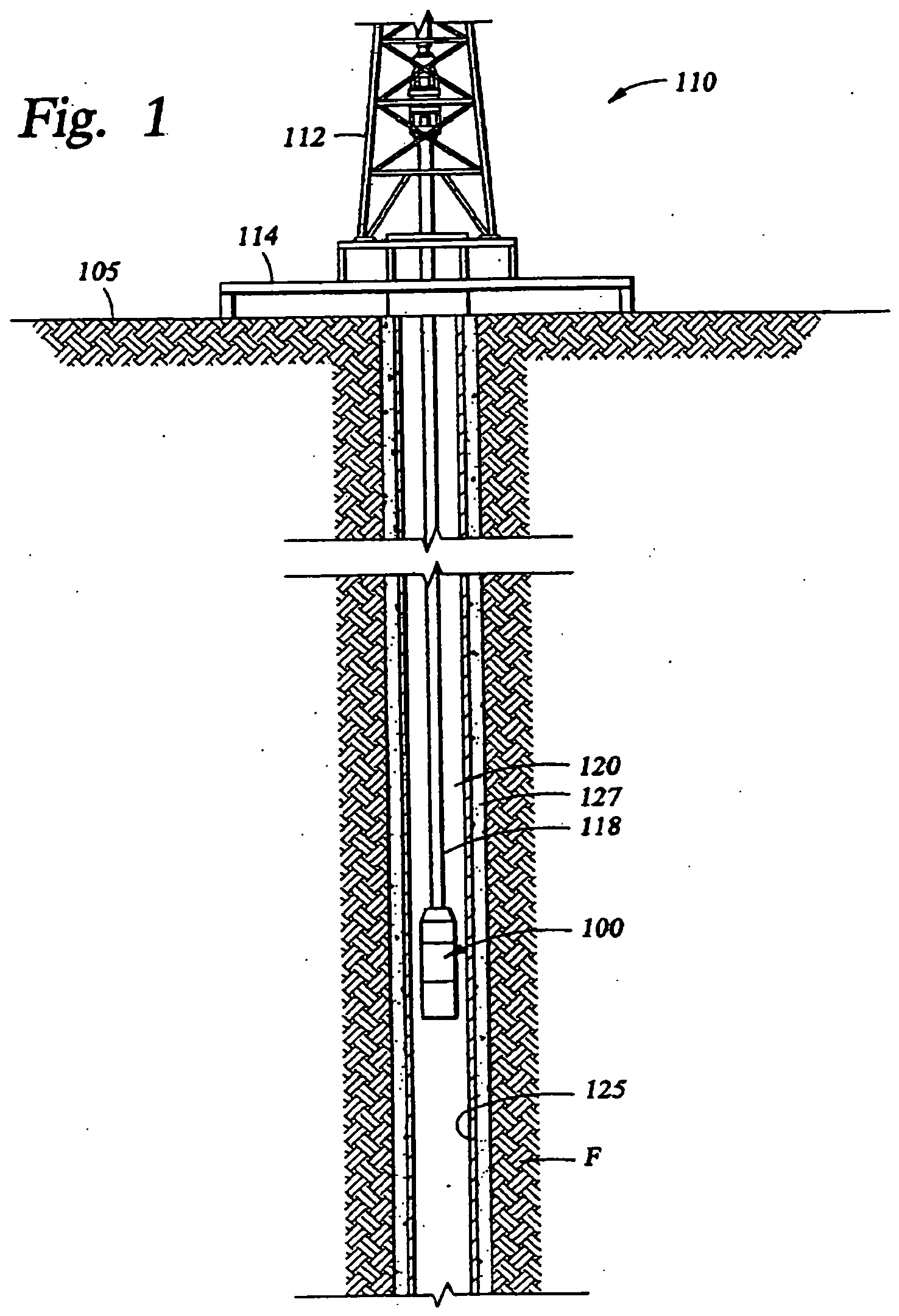
This figure does not illustrate all of the features of the invention as claimed but is included to aid the understanding of the invention and how the torch of the claimed system can be disposed in a well bore.
Fe2O3 + 2Al(s) → Al2O3(s) + 2Fe(l)
3Mg + Al2O3 → 3MgO + 2Al
characterised in that