HEAT PUMP WITH EJECTOR
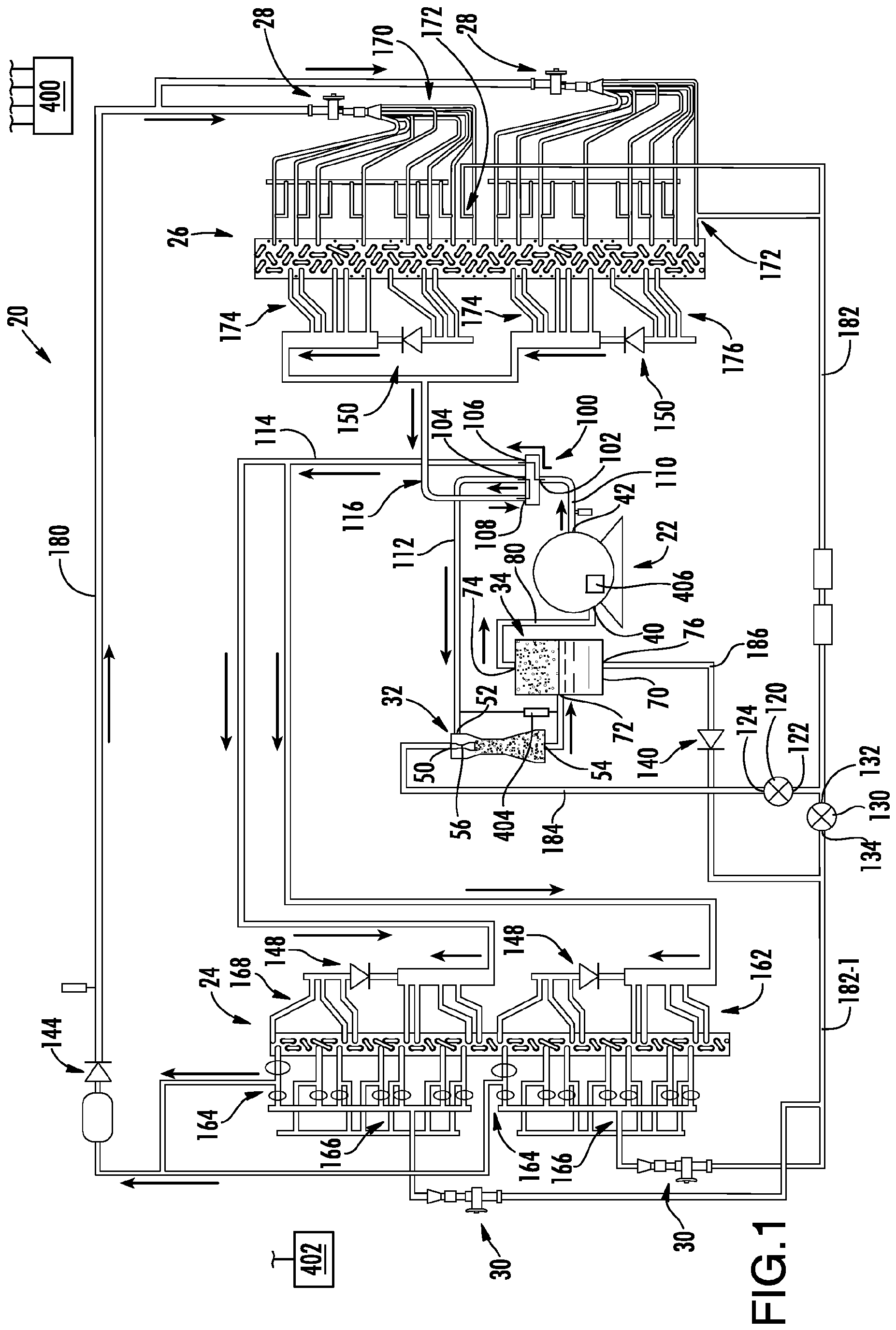
The invention relates to heat pumps. More particularly, the invention relates to heat pumps featuring an ejector. Vapor compression systems have long been used for air conditioning. An exemplary vapor compression air conditioner comprises a refrigerant compressor, an outdoor heat exchanger downstream of the compressor along a refrigerant flowpath, an expansion device downstream of the outdoor heat exchanger, and an indoor heat exchanger downstream of the expansion device prior to the refrigerant flowpath returning to the compressor. Refrigerant is compressed in the compressor. Refrigerant then rejects heat in the outdoor heat exchanger and loses temperature. An exemplary outdoor heat exchanger is a refrigerant-air heat exchanger wherein fan-forced outdoor air acquires heat from refrigerant. By rejecting heat, the refrigerant may condense from vapor to liquid in the heat rejection heat exchanger. Accordingly, such exchangers are often referred to as condensers. In other systems, the refrigerant remains vapor and such are referred to as gas coolers. The refrigerant expands in the expansion device and decreases in temperature. The reduced temperature of the refrigerant thus absorbs heat in the heat absorption heat exchanger (e.g., evaporator). Again, the evaporator may be a refrigerant-air heat exchanger across which a fan-forced interior/indoor airflow is driven with the interior/indoor airflow rejecting heat to the refrigerant. Such vapor compression systems may also be used to heat interior spaces. In such cases, the refrigerant flow direction is altered to pass first from the compressor to the indoor heat exchanger and return from the outdoor heat exchanger to the compressor. Such arrangements are referred to as heat pumps. In addition to simple expansion devices such as orifices and valves, ejectors have been used as expansion devices. Ejectors are particularly efficient where there is a large temperature difference between the indoor and outdoor environments. An exemplary ejector is formed as the combination of a motive (primary) nozzle nested within an outer member or body. The ejector has a motive flow inlet (primary inlet) which may form the inlet to the motive nozzle. The ejector outlet may be the outlet of the outer member. A motive/primary refrigerant flow enters the inlet and then passes into a convergent section of the motive nozzle. It then passes through a throat section and an expansion (divergent) section and through an outlet of the motive nozzle. The motive nozzle accelerates the flow and decreases the pressure of the flow. The ejector has a secondary inlet forming an inlet of the outer member. The pressure reduction caused to the primary flow by the motive nozzle helps draw a suction flow or secondary flow into the outer member through the suction port. The outer member may include a mixer having a convergent section and an elongate throat or mixing section. The outer member also has a divergent section or diffuser downstream of the elongate throat or mixing section. The motive nozzle outlet may be positioned within the convergent section. As the motive flow exits the motive nozzle outlet, it begins to mix with the suction flow with further mixing occurring through the mixing section which provides a mixing zone. Ejectors may be used with a conventional refrigerant or a COz-based refrigerant. In an exemplary operation with CO2, the motive flow may typically be supercritical upon entering the ejector and subcritical upon exiting the motive nozzle. The secondary flow is gaseous (or a mixture of gas with a smaller amount of liquid) upon entering the secondary inlet. The resulting combined flow is a liquid/vapor mixture and decelerates and recovers pressure in the diffuser while remaining a mixture. One aspect of the invention involves a system according to claim 1, the system comprising: a compressor having a suction port and a discharge port; an ejector having a motive flow inlet, a suction flow inlet, and an outlet; a separator having an inlet, a vapor outlet, and a liquid outlet; a first heat exchanger; a first expansion device; a second heat exchanger; a second expansion device; and a plurality of conduits and a plurality of valves. The conduits and valves are positioned to provide alternative operation in three modes. In a first mode, a refrigerant flow is sequentially: passed from the compressor to the first heat exchanger; expanded in the first expansion device; passed through the second heat exchanger; passed to the suction flow inlet; passed from the ejector outlet to the separator inlet; and passed from the vapor outlet to the suction port. In a second mode, a refrigerant flow is sequentially: passed from the compressor to the second heat exchanger; passed to the motive flow inlet; mixed with an ejector suction flow passed through the suction flow inlet; passed from the ejector outlet to the separator inlet; separated in the separator into: a compressor suction flow passed to the suction port; and said ejector suction flow expanded in the second expansion device and passed through the first heat exchanger before reaching the ejector suction inlet. In a third mode, a refrigerant flow is sequentially: passed from the compressor to the second heat exchanger; expanded in the second expansion device; passed through the first heat exchanger; passed to the suction flow inlet; passed from the ejector outlet to the separator inlet; and passed from the vapor outlet to the suction port. In one or more embodiments of any of the foregoing embodiments, the plurality of valves comprise a plurality of one-way check valves. In one or more embodiments of any of the foregoing embodiments, the plurality of valves comprise: a first solenoid valve positioned to: in the first mode: block flow through the motive flow inlet; and in the second mode: pass flow from the second heat exchanger to the motive flow inlet; and a second solenoid valve positioned to: in the second mode: block flow from passing from the second heat exchanger directly to the first expansion device. In one or more embodiments of any of the foregoing embodiments, the second solenoid valve is positioned to in the first mode prevent flow leakage from the first heat exchanger to the second heat exchanger. In one or more embodiments of any of the foregoing embodiments, the plurality of valves comprise a three-way valve positioned to: in the first mode: block flow through the motive flow inlet and prevent flow leakage from the first heat exchanger to the second heat exchanger; and in the second mode: pass flow from the second heat exchanger to the motive flow inlet and block flow from passing from the second heat exchanger directly to the first expansion device. In one or more embodiments of any of the foregoing embodiments, the plurality of valves comprise a switching valve having: a first port positioned to receive flow from the compressor discharge port; a second port positioned to pass flow to the ejector suction port; a third port positioned to communicate with the first heat exchanger; and a fourth port positioned to communicate with the second heat exchanger. In one or more embodiments of any of the foregoing embodiments, the system has only a single ejector. In one or more embodiments of any of the foregoing embodiments, the system has only a single four-port switching valve. In one or more embodiments of any of the foregoing embodiments, the remaining said valves are only check valves and on-off solenoid valves or only check valves and a single three-way valve. In one or more embodiments of any of the foregoing embodiments, the first heat rejection heat exchanger is a refrigerant-air heat exchanger; and the second heat rejection heat exchanger is a refrigerant-air heat exchanger. In one or more embodiments of any of the foregoing embodiments, in the first mode and the third mode, there is no ejector motive flow. In one or more embodiments of any of the foregoing embodiments, a controller is configured to switch the system between: running in the first mode; running in the second mode; and running in the third mode. In one or more embodiments of any of the foregoing embodiments, the controller is configured to switch the system between said second mode and said third mode based on a sensed outdoor temperature. In one or more embodiments of any of the foregoing embodiments, a method for using the system comprises: running in the first mode; running in the second mode; and running in the third mode. In one or more embodiments of any of the foregoing embodiments, the method further comprises selecting which of the second mode and third mode in which to run based at least partially on a sensed outdoor temperature. In one or more embodiments of any of the foregoing embodiments, a switching between at least two of the modes comprises actuating a single 4-way switching valve and no more than one 3-way switching valve. In one or more embodiments of any of the foregoing embodiments, the switching between at least two of the modes comprises a switching between at least two of the modes comprises actuating a single 4-way switching valve, no 3-way switching valves, and a plurality of 2-way solenoid valves. The details of one or more embodiments are set forth in the accompanying drawings and the description below. Other features, objects, and advantages will be apparent from the description and drawings, and from the claims. Like reference numbers and designations in the various drawings indicate like elements. The exemplary illustrated system is shown as a schematically marked-up modification of a baseline Carrier 50HCQ heat pump of Carrier Corporation. That baseline system had two compressors servicing respective circuits, each having its own sections of the indoor coil (heat exchanger 26) and outdoor coil (heat exchanger 24) for full redundancy. The exemplary modification replaces the two compressors with a single compressor but retains the splitting of the coils for partial redundancy. Nevertheless, dual compressors (or more) and/or multiple (or single) circuits are possible. In the In the The exemplary system includes one or more first expansion devices 28 and one or more second expansion devices 30. As is discussed further below, the system also includes an ejector 32 and a separator 34. The The compressor has a suction port (inlet) 40 and a discharge port (outlet) 42. The ejector comprises a motive flow inlet (primary inlet) 50, a suction flow inlet (secondary flow inlet) 52 and an outlet 54. The exemplary ejector comprises a motive flow nozzle 56 positioned to receive a motive flow through the motive flow inlet 50 upstream of a mixing location for flow delivered through the suction flow inlet 52. The separator 34 comprises a vessel 70 having an inlet port 72, a vapor outlet 74, and a liquid outlet 76. A liquid accumulation may be in a lower portion of the vessel and vapor in its headspace. A compressor suction line 80 extends between vapor outlet 74 and the compressor suction port 40. Interconnecting the various components are a plurality of conduits and a plurality of additional components including valves, filters, strainers, and the like. As is discussed further below, the valves include a four-way switching valve 100 having a first port 102. The first port serves as an inlet connected to the discharge port 42 of the compressor via an associated discharge line 110. The switching valve 100 further comprises a second port 104, a third port 106, and a fourth port 108. The exemplary valve is configured with a rotary valve element having passageways for establishing two conditions of operation: selectively placing the first port 102 in communication with one of the third port and fourth port while placing the second port 104 in communication with the other. Actuation of the valve element between these two conditions, along with other valve actuations discussed below, facilitates transition between the three modes of operation. The Similarly, each heat exchanger 26 or section thereof has a port 170 (e.g., shown as a manifold) associated with the expansion device(s) 28, an outlet port 172 (used only during heating) to the compressor, and ports 174 and 176 shown as manifolds. Each exemplary check valve 150 is positioned between an associated port 174 and 176. In the cooling mode, the check valve 150 is positioned to permit parallel flow through these ports to, in turn, pass to the ejector and return to the compressor. The return flow from the heat exchanger 26 is essentially vapor and passes as vapor through the ejector suction port, ejector outlet, and separator 34, exiting the vapor outlet 74 to return to the compressor suction port 40. Prior to reaching ejector suction port 52, the refrigerant passes through the ports 108 and 104 of the switching valve 100. A defrost mode (not shown) for defrosting the heat exchanger 24 may be similar to the In an alternative configuration 300 of The In the The presence of the check valve 144 and line 180 prevents flow from passing in reverse through the port(s) 170 and expansion device(s) 28. Accordingly, all flow leaves through the port(s) 172 to a line 182. The refrigerant is diverted into a branch line 184 via a closed valve 130 in the line 182. In this mode, the valve 120 is open. The line 184 goes to the ejector motive inlet 50 to deliver the motive flow to the ejector. The suction flow of the ejector is provided by a return from the heat exchanger(s) 24 as is discussed below. Flow, however, is delivered through a terminal portion 182-1 of the line 182 to the valve(s) 30 via a line 186 extending from the liquid outlet 76 of the separator so as to deliver liquid refrigerant. Line 186 intersects the line 182 downstream of the valve 130 (closed in this condition) and the check valve 142. In the exemplary embodiment, refrigerant will not pass out the port(s) 164 because the heat exchanger 24 is at lower pressure than the heat exchanger 26 and, therefore, no additional check or other valves need be provided to block flow along the line 180. The refrigerant flow exiting the heat exchanger(s) 24 will pass through both the outlets 162 and 168. This will pass through the outlets 168 because of the orientation of the check valves 148 to permit this flow. These flow(s) proceed back via line 114 to the port 106 of the switching valve 100 and then out the port 104 via line 112 to the ejector suction inlet 52. This flow combined with the motive flow from line 184 enters the separator where it is separated. A vapor flow exits the port 74 to return along the compressor suction line to the compressor suction port 40. The liquid flow passes out the outlet 76 into the line 186 as was discussed above. The The Thus, in the In the In the The Again, the refrigerant from the heat exchanger 26 is expanded in the expansion device 520 to provide expanded/cooled refrigerant to the heat exchanger 24. Thus, another characteristic of this third embodiment is that the same line 182 serves as the liquid line in all three modes. A further defrost mode may be as discussed regarding the prior embodiments. A control routine may be programmed or otherwise configured into the controller. The routine provides automatic selection of which of the two heating modes to use based on sensed conditions. In a reengineering of a baseline heat pump system, this selection may be superimposed upon the controller's normal programming/routines (e.g., providing the basic operation of baseline system to which the foregoing mode control is added). In one example, the switching of the two heating modes can be controlled responsive only to the outdoor ambient temperature sensor 402 and/or a pressure transducer 404 (positioned to sense pressure difference between the ejector port 52 and port 54), and/or the compressor speed signal (from a sensor 406 or logic internal to the controller). For example, the ejector can be enabled during the heating mode once the temperature sensor 402 reading is below a threshold (e.g., 32°F (0°C)), and/or once the pressure sensor 404 reading is less than a certain target number (e.g., 2psid (14kPa)), and/or once the compressor reaches its minimum speed. The use of "first", "second", and the like in the description and following claims is for differentiation within the claim only and does not necessarily indicate relative or absolute importance or temporal order. Similarly, the identification in a claim of one element as "first" (or the like) does not preclude such "first" element from identifying an element that is referred to as "second" (or the like) in another claim or in the description. Where a measure is given in English units followed by a parenthetical containing SI or other units, the parenthetical's units are a conversion and should not imply a degree of precision not found in the English units. One or more embodiments have been described. Nevertheless, it will be understood that various modifications may be made. For example, when applied to an existing basic system, details of such configuration or its associated use may influence details of particular implementations. Accordingly, other embodiments are within the scope of the following claims. A system (20; 300) comprising:
a compressor (22) having a suction port (40) and a discharge port (42); an ejector (32) having a motive flow inlet (50), a suction flow inlet (52), and an outlet (54); a separator (34) having an inlet (72), a vapor outlet (74), and a liquid outlet (76); a first heat exchanger (24); a first expansion device (28); a second heat exchanger (26); a second expansion device (30); and a plurality of conduits and a plurality of valves (100, 120, 130, 140, 144, 148, 150; 100, 140, 144, 148, 150, 320, 340) configured to provide alternative operation in:
a first mode wherein a refrigerant flow is sequentially:
passed from the compressor to the first heat exchanger; expanded in the first expansion device; passed through the second heat exchanger; passed to the suction flow inlet; passed from the ejector outlet to the separator inlet; and passed from the vapor outlet to the suction port; a second mode wherein a refrigerant flow is sequentially:
passed from the compressor to the second heat exchanger; passed to the motive flow inlet; mixed with an ejector suction flow passed through the suction flow inlet; passed from the ejector outlet to the separator inlet; separated in the separator into:
a compressor suction flow passed to the suction port; and said ejector suction flow expanded in the second expansion device and passed through the first heat exchanger before reaching the ejector suction inlet; and, a third mode wherein a refrigerant flow is sequentially:
passed from the compressor to the second heat exchanger; expanded in the second expansion device; passed through the first heat exchanger; passed to the suction flow inlet; passed from the ejector outlet to the separator inlet; and passed from the vapor outlet to the suction port. The system of claim 1 wherein the plurality of valves comprise: The system of claim 1 wherein the plurality of valves comprise: in the first mode: in the second mode: in the second mode: The system of claim 3 wherein: The system of claim 1 wherein the plurality of valves comprise: in the first mode: in the second mode: The system of claim 1 wherein the plurality of valves comprise: a first port (102) positioned to receive flow from the compressor discharge port; a second port (104) positioned to pass flow to the ejector suction port; a third port (106) positioned to communicate with the first heat exchanger; and a fourth port (108) positioned to communicate with the second heat exchanger. The system of claim 1 wherein: The system of claim 1 wherein: The system of claim 8 wherein: The system of claim 1 wherein:
the first heat rejection heat exchanger is a refrigerant-air heat exchanger; and the second heat rejection heat exchanger is a refrigerant-air heat exchanger. The system of claim 1 wherein:BACKGROUND
SUMMARY
BRIEF DESCRIPTION OF THE DRAWINGS
DETAILED DESCRIPTION
a plurality of one-way check valves (140, 144, 148, 150; 140, 144, 148, 150, 340).
a first solenoid valve (120) positioned to:
block flow through the motive flow inlet; and
pass flow from the second heat exchanger to the motive flow inlet; and a second solenoid valve (130) positioned to:
block flow from passing from the second heat exchanger directly to the first expansion device.
the second solenoid valve is positioned to in the first mode prevent flow leakage from the first heat exchanger to the second heat exchanger.
a three-way valve (320) positioned to:
block flow through the motive flow inlet and prevent flow leakage from the first heat exchanger to the second heat exchanger; and
pass flow from the second heat exchanger to the motive flow inlet and block flow from passing from the second heat exchanger directly to the first expansion device.
a switching valve (100) having:
the system has only a single ejector.
the system has only a single four-port switching valve (100).
the remaining said valves are only check valves and on-off solenoid valves or only check valves and a single three-way valve.
in the first mode and the third mode, there is no ejector motive flow.


CPC - классификация
FF2F25F25BF25B1F25B13F25B13/F25B13/0F25B13/00F25B2F25B23F25B234F25B2341F25B2341/F25B2341/0F25B2341/00F25B2341/001F25B2341/0011F25B24F25B240F25B2400F25B2400/F25B2400/2F25B2400/23F25B27F25B270F25B2700F25B2700/F25B2700/2F25B2700/21F25B2700/210F25B2700/2106F25B4F25B41F25B41/F25B41/2F25B41/20F25B41/22F25B41/3F25B41/38F25B41/385IPC - классификация
FF2F25F25BF25B1F25B13F25B13/F25B13/0F25B13/00F25B4F25B41F25B41/F25B41/2F25B41/20F25B41/22F25B41/3F25B41/38F25B41/385Цитирование НПИ
EP-A1- 2 728 278US-A1- 2003 140 651
US-A1- 2012 180 510