HOT GAS DEFROST USING DEDICATED LOW TEMPERATURE COMPRESSOR DISCHARGE
This disclosure relates generally to refrigeration systems and methods of their use. More particularly, in certain embodiments, this disclosure relates to hot gas defrost using dedicated low temperature compressor discharge. Refrigeration systems are used to regulate environmental conditions within an enclosed space. Refrigeration systems are used for a variety of applications, such as in supermarkets and warehouses, to cool stored items. For example, refrigeration systems may provide cooling operations for refrigerators and freezers. During operation of refrigeration systems, ice may build up on evaporators. These evaporators need to be defrosted to remove ice buildup and prevent loss of performance. Previous evaporator defrost processes are limited in terms of their efficiency and effectiveness. For example, using previous technology, defrost processes may take a relatively long time and consume a relatively large amount of energy. In some cases, previous technology may be incapable of providing adequate defrosting, for instance, in cases where a relatively large number of evaporators need to be defrosted in a multiple-evaporator refrigeration system. This disclosure provides technical solutions to the problems of previous technology, including those described above. For example, a refrigeration system is described that facilitates improved evaporator defrost using a dedicated defrost-mode compressor. The dedicated defrost-mode compressor may operate at a higher suction pressure and discharge pressures than typical low temperature compressors in order to further improve defrost performance. A corresponding dedicated suction and discharge line facilitate flow of appropriately warmed and compressed refrigerant to one or more evaporators during defrost mode operation. In some embodiments, a pressure switch in the discharge line may ensure an excessive pressure is not provided during defrost, thereby preventing damage to evaporators being defrosted. When operating to provide defrost to one or more evaporators, the dedicated defrost-mode compressor is supplied with superheated gas generated by a heat exchanger and expansion valve that are located downstream of the system's gas cooler. In some case, evaporators of the refrigeration system may be specially configured to have to operate at increased pressures to facilitate this new defrost process. Embodiments of this disclosure may provide improved defrost operations to evaporators of refrigeration systems, such as CO2 transcritical refrigeration systems. The system is configured to provide an increased pressure differential to drive refrigerant flow in defrost mode operation. While one or a portion of the evaporators of the refrigeration system are operating, low-temperature compressors used for refrigeration can still operate as usual without requiring increased pressure operation and without unnecessarily increasing power consumption. The heat exchanger of the refrigeration system not only facilitates the improved defrost process but also lowers power consumption during refrigeration by further cooling refrigerant from the gas cooler. As such, the refrigeration system of this disclosure provides improved defrost operations while also improving the energy efficiency of the refrigeration system. Certain embodiments may include none, some, or all of the above technical advantages. One or more other technical advantages may be readily apparent to one skilled in the art from the figures, descriptions, and claims included herein. In an embodiment, a refrigeration system includes a gas cooler, a heat exchanger located downstream from the gas cooler, a flash tank located downstream a first outlet of the heat exchanger (e.g., downstream a high pressure expansion valve (HPEV)), a defrost-mode compressor located downstream a second outlet of the heat exchanger, a first evaporator unit located downstream from the flash tank, and a controller communicatively coupled to the defrost-mode compressor. The flash tank is configured to store refrigerant. The gas cooler is configured to receive high pressure, high temperature refrigerant and facilitate heat transfer from the received refrigerant to ambient air, thereby cooling the refrigerant. The controller is configured to determine when the first evaporator unit needs to be defrosted. (i.e., that operation of the first evaporator unit in a defrost mode is indicated). After determining that the first evaporator unit needs to be defrosted, in the defrost mode is indicated, the controller causes the first evaporator unit to operate in the defrost mode by causing the defrost-mode compressor to turn on. When the defrost-mode compressor is turned on, the heat exchanger is configured to receive a portion of refrigerant stored by the flash tank and transfer heat to the received portion of refrigerant from the refrigerant cooled by the gas cooler, thereby heating the received portion of refrigerant. The defrost-mode compressor is configured, while turned on, to compress this heated refrigerant to high pressure and deliver to the first evaporator unit, thereby defrosting an evaporator of the first evaporator unit. For a more complete understanding of the present disclosure, reference is now made to the following description, taken in conjunction with the accompanying drawings, in which:
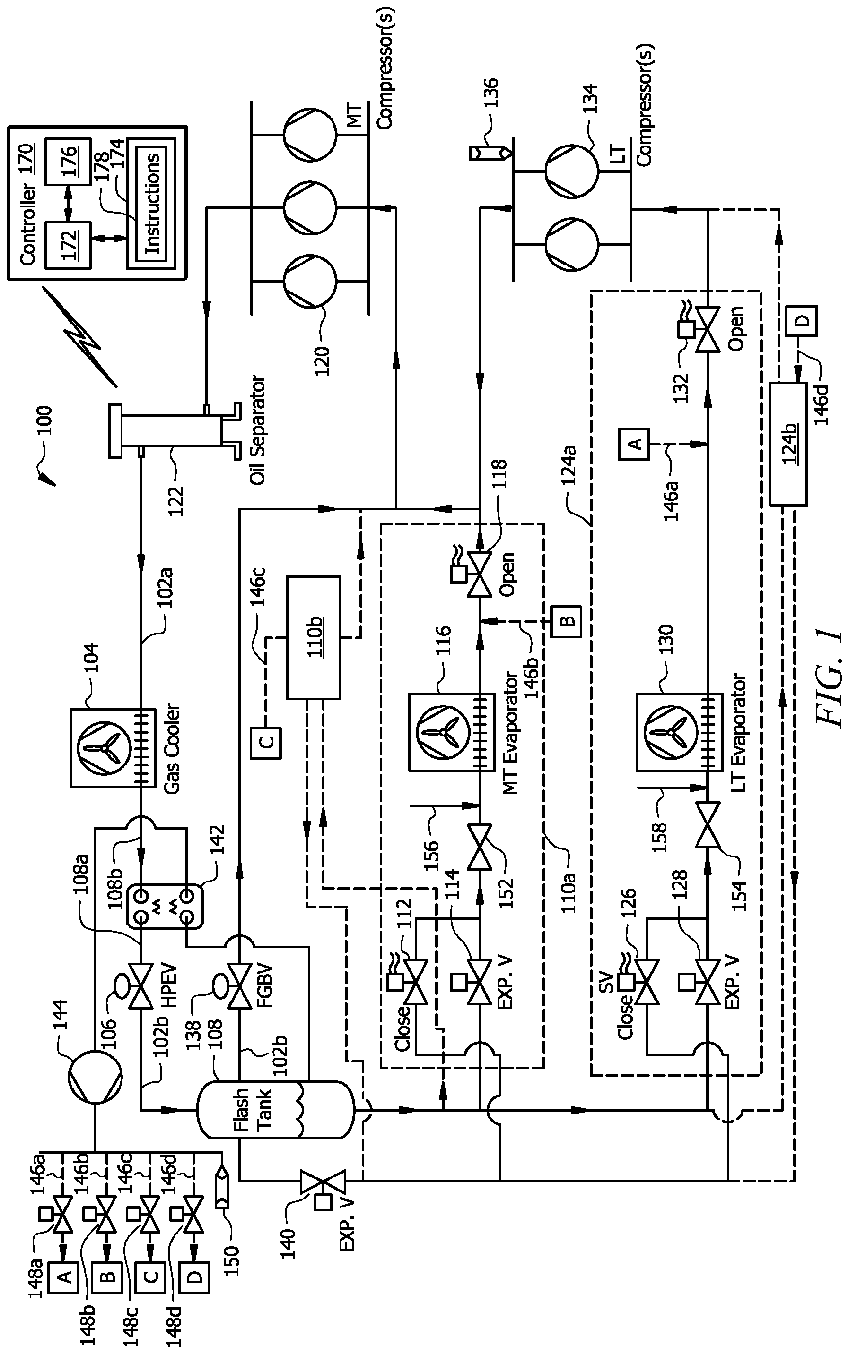
Embodiments of the present disclosure and its advantages are best understood by referring to As described above, prior to this disclosure, defrost operations of refrigeration systems suffered from certain inefficiencies and drawbacks. The refrigeration system of this disclosure provides improvements in defrost performance and energy efficiency. In some cases, the refrigeration system may ensure that all appropriate defrost operations can be performed when needed, while previous technology may have been limited in the number of evaporators that could be defrosted at a given time or over a given period of time. The refrigeration system of this disclosure may be a CO2 transcritical refrigeration system. CO2 transcritical refrigeration systems differ from conventional refrigeration systems in that transcritical systems circulate refrigerant that becomes a supercritical fluid (i.e., where distinct liquid and gas phases are not present) above the critical point. As an example, the critical point for carbon dioxide (CO2) is 31°C and 73.8 MPa, and above this point, CO2 becomes a homogenous mixture of vapor and liquid that is called a supercritical fluid. This unique characteristic of transcritical refrigerants is associated with certain operational differences between transcritical and conventional refrigeration systems. For example, transcritical refrigerants are typically associated with discharge temperatures that are higher than their critical temperatures and discharge pressures that are higher than their critical pressures. When a transcritical refrigerant is at or above its critical temperature and/or pressure, the refrigerant may become a "supercritical fluid" - a homogenous mixture of gas and liquid. Supercritical fluid does not undergo phase change process (vapor to liquid) in a gas cooler as occurs in a condenser of a conventional refrigeration system circulating traditional refrigerant. Rather, supercritical fluid cools down to a lower temperature in the gas cooler. Stated differently, the gas cooler in a CO2 transcritical refrigeration system receives and cools supercritical fluid and the transcritical refrigerant undergoes a partial state change from gas to liquid as it is discharged from an expansion valve. Refrigeration system 100 includes refrigerant conduit subsystem 102, gas cooler 104, heat exchanger 142, expansion valve 106, flash tank 108, one or more medium-temperature (MT) evaporator units 110a,b, one or more MT compressors 120, an oil separator 122, one or more low-temperature (LT) evaporator units 124a,b, one or more LT compressors 134, pressure-relief valves 136, 150, a bypass valve 138, an expansion valve 140, a defrost-mode compressor 144, refrigerant conduit 146a-d, optionally valves 148a-d, and controller 170. In some embodiments, refrigeration system 100 is a transcritical refrigeration system that circulates a transcritical refrigerant such as CO2. Refrigerant conduit subsystem 102 facilitates the movement of refrigerant (e.g., CO2) through a refrigeration cycle such that the refrigerant flows in the refrigeration mode as illustrated by the arrows in Gas cooler 104 is generally operable to receive refrigerant (e.g., from MT compressor(s) 134 or oil separator 122) and apply a cooling stage to the received refrigerant. In some embodiments, gas cooler 104 is a heat exchanger comprising cooler tubes configured to circulate the received refrigerant and coils through which ambient air is forced. Inside gas cooler 104, the coils may absorb heat from the refrigerant, thereby cooling the refrigerant. Heat exchanger 142 is located downstream of the gas cooler 104 and configured to receive cooled refrigerant from the gas cooler 104. When at least one of the evaporator units 110a,b, 124a,b is operating in defrost mode, as shown in Heat exchanger 142 discharges refrigerant, whether not further cooled as in Flash tank 108 is configured to receive mixed-state refrigerant and separate the received refrigerant into flash gas and liquid refrigerant. Typically, the flash gas collects near the top of flash tank 108 and the liquid refrigerant is collected in the bottom of flash tank 108. In some embodiments, the liquid refrigerant flows from flash tank 108 and provides cooling to the MT evaporator units 110a,b and LT evaporator units 124a,b. When operated in refrigeration mode (see When the MT evaporator unit 110a is operating in the refrigeration mode illustrated in When the MT evaporator unit 110a is operating in the defrost mode illustrated in Valves 112 and 118 may be in communication with controller 170, and the controller 170 may provide instructions for adjusting the valves 112, 118 to open or closed positions to achieve the configuration of Once defrost mode operation is complete, the controller 170 may end defrost mode operation by turning off the defrost-mode compressor 144, closing first valve 112, and opening second valve 118 to return to the refrigeration mode configuration illustrated in Refrigerant from the MT evaporator units 110a,b that are operating in refrigeration mode (i.e., MT evaporator units 110a and 110b in LT evaporator units 124a,b are generally similar to the MT evaporator units 110a,b but configured to operate at lower temperatures (e.g., for deep freezing applications near about -30 °C or the like). When operated in refrigeration mode (see When the LT evaporator unit 124a is operating in the refrigeration mode illustrated in When the LT evaporator unit 124a is operating in the defrost mode illustrated in Valves 126 and 132 may be in communication with controller 170, and the controller 170 may provide instructions for adjusting the valves 126, 132 to open or closed positions to achieve the configuration of Once defrost mode operation is complete, the controller 170 may end defrost mode operation by turning off the defrost-mode compressor 144, closing first valve 126, and opening second valve 132 to return to the refrigeration mode configuration illustrated in Refrigerant from the LT evaporator units 124a,b that are operating in refrigeration mode (i.e., LT evaporator units 124a and 124b in Flash gas bypass valve 138 may be located in refrigerant conduit connecting the flash tank 108 to the MT compressors 120 and configured to open and close to permit or restrict the flow of flash gas discharged from flash tank 108. In some embodiments, controller 170 controls the opening and closing of flash gas bypass valve 138. As depicted in The oil separator 122 may be located downstream the MT compressors 120. The oil separator 122 is operable to separate compressor lubrication oil from the refrigerant. The refrigerant is provided to the gas cooler 104, while the oil may be collected and returned to the MT compressors 120, as appropriate. The defrost-mode compressor 144 is located downstream from the heat exchanger 142 and in fluid communication with the MT evaporator units 110a,b and LT evaporator units 124a,b via fluid conduits 146a-d. The defrost-mode compressor 144 is configured, when turned on, to compress refrigerant discharged from the heat exchanger 142. In some embodiments, each of the refrigerant conduits 146a-d includes a corresponding controllable valve 148a-d to adjust the flow of refrigerant through the corresponding conduit 146a-d. This may facilitate control of the distribution of refrigerant to two or more evaporator units 110a,b, 124a,b that are operated in defrost mode at the same time. Valves 148a-d may be in communication with and controlled by controller 170. A pressure-relief valve 150 may be in line with refrigerant conduits 146a-d, as illustrated in As described above, controller 170 is in communication with at least the defrost-mode compressor 144, valves 112, 118 of the MT evaporator units 110a,b, and valves 126, 132 of the LT evaporator units 124a,b. The controller 170 adjusts operation of components of the refrigeration system 100 to operate the evaporator units 110a,b, 124a,b in refrigeration mode or defrost mode as appropriate. The controller includes a processor 172, memory 174, and input/output (I/O) interface 176. The processor 172 includes one or more processors operably coupled to the memory 174. The processor 172 is any electronic circuitry including, but not limited to, state machines, one or more central processing unit (CPU) chips, logic units, cores (e.g. a multi-core processor), field-programmable gate array (FPGAs), application specific integrated circuits (ASICs), or digital signal processors (DSPs) that communicatively couples to memory 174 and controls the operation of refrigeration system 100. The processor 172 may be a programmable logic device, a microcontroller, a microprocessor, or any suitable combination of the preceding. The processor 172 is communicatively coupled to and in signal communication with the memory 174. The one or more processors are configured to process data and may be implemented in hardware or software. For example, the processor 172 may be 8-bit, 16-bit, 32-bit, 64-bit or of any other suitable architecture. The processor 172 may include an arithmetic logic unit (ALU) for performing arithmetic and logic operations, processor registers that supply operands to the ALU and store the results of ALU operations, and a control unit that fetches instructions from memory 174 and executes them by directing the coordinated operations of the ALU, registers, and other components. The processor 172 may include other hardware and software that operates to process information, control the refrigeration system 100, and perform any of the functions described herein (e.g., with respect to The memory 174 includes one or more disks, tape drives, or solid-state drives, and may be used as an over-flow data storage device, to store programs when such programs are selected for execution, and to store instructions and data that are read during program execution. The memory 174 may be volatile or non-volatile and may include ROM, RAM, ternary content-addressable memory (TCAM), dynamic random-access memory (DRAM), and static random-access memory (SRAM). The memory 174 is operable (e.g., or configured) to store information used by the controller 170 and/or any other logic and/or instructions for performing the function described in this disclosure. For example, the memory 174 may store instructions 178 for performing the functions of the controller 170 described in this disclosure. The instructions 178 may include, for example, a schedule for performing defrost mode operations, threshold temperature and/or pressure levels for determining when defrost is complete (e.g., based on information from sensors 156, 158 or other sensors of the refrigeration system 100), and the like. The I/O interface 176 is configured to communicate data and signals with other devices. For example, the I/O interface 176 may be configured to communicate electrical signals with components of the refrigeration system 100 including the compressors 120, 134, 144, gas cooler 104, valves 106, 112, 114, 118, 126, 128, 132, 138, 140, 148a-d, evaporators 116, 130, and sensors 156, 158. The I/O interface 176 may be configured to communicate with other devices and systems. The I/O interface 176 may provide and/or receive, for example, compressor speed signals, compressor on/off signals, temperature signals, pressure signals, temperature setpoints, environmental conditions, and an operating mode status for the refrigeration system 100 and send electrical signals to the components of the refrigeration system 100. The I/O interface 176 may include ports or terminals for establishing signal communications between the controller 170 and other devices. The I/O interface 176 may be configured to enable wired and/or wireless communications. Although this disclosure describes and depicts refrigeration system 100 including certain components, this disclosure recognizes that refrigeration system 100 may include any suitable components. As an example, refrigeration system 100 may include one or more additional sensors configured to detect temperature and/or pressure information. In some embodiments, each of the compressors 120, 134, 144, heat exchanger 142, gas cooler 104, flash tank 108, and evaporators 116, 130 include one or more sensors. In an example operation of the refrigeration system 100, the refrigeration system 100 is initially operating with all evaporator units 110a,b, 124a,b in the refrigeration mode, as illustrated in At some point during operation of the refrigeration system 100, the controller 170 determines that defrost mode operation is needed for the first MT evaporator unit 110a and the first LT evaporator unit 124a. For example, the first MT evaporator unit 110a and the first LT evaporator unit 124a may be scheduled for defrost at the same time that has just been reached. After determining that the defrost mode operation is indicated, the controller 170 causes the first MT evaporator 110a and the first LT evaporator 124a to be configured according to With the defrost-mode compressor 144 turned on, a portion of refrigerant from flash tank 108 is provided to the heat exchanger 142. Heat transfer between this portion of refrigerant and the refrigerant from gas cooler 104 causes the portion of refrigerant from the flash tank 108 to increase in temperature. Meanwhile, the refrigerant from the gas cooler is further cooled, providing improved refrigeration performance for the other evaporator units 110b, 124b that are still operating in the refrigeration mode. The heated refrigerant from the heat exchanger 142 is compressed by compressor 144 and provided to the evaporator units 110a, 124a, as illustrated in At step 406, the controller 170 causes the first valve 112, 126 to open and the second valve 118, 132 to close in the evaporator unit 110a,b, 124a,b for which defrost mode operation was indicated at step 402. This achieves the defrost mode configuration illustrated in At step 408, the controller 170 turns on the defrost-mode compressor 144. After being turned on, the defrost-mode compressor causes a portion of refrigerant from the flash tank 108 to flow to the heat exchanger 142 (e.g., to the second inlet 306 shown in At step 412, the controller 170 determines whether defrost conditions are satisfied for ending defrost mode operation. The defrost conditions may be indicated by the instructions 178 stored in the memory 174 of the controller 170. For example, the defrost conditions may indicate that defrost mode operation must be performed for a predefined period of time. As another example, the defrost conditions may indicate that an output temperature at or near the positions of sensor 156, 158 must increase to at least a predefined temperature (e.g., of about 11 °C) before defrost mode operation is complete. If the defrost conditions are not met, the controller 170 proceeds to step 414 to wait a period of time before returning to step 412. If the defrost conditions of step 412 are satisfied, the controller 170 proceeds to step 404 and returns to operating in the refrigeration mode. In order to operate in the refrigeration mode at step 404, the controller 170 may cause the first valve 112, 126 to close and the second valve 118, 132 to open. If no other evaporator unit 110a,b, 124a,b is operating in the defrost mode, the defrost-mode compressor 144 is turned off. Modifications, additions, or omissions may be made to method 400 depicted in While several embodiments have been provided in the present disclosure, it should be understood that the disclosed systems and methods might be embodied in many other specific forms without departing from the spirit or scope of the present disclosure. The present examples are to be considered as illustrative and not restrictive, and the intention is not to be limited to the details given herein. For example, the various elements or components may be combined or integrated in another system or certain features may be omitted, or not implemented. In addition, techniques, systems, subsystems, and methods described and illustrated in the various embodiments as discrete or separate may be combined or integrated with other systems, modules, techniques, or methods without departing from the scope of the present disclosure. Other items shown or discussed as coupled or directly coupled or communicating with each other may be indirectly coupled or communicating through some interface, device, or intermediate component whether electrically, mechanically, or otherwise. Other examples of changes, substitutions, and alterations are ascertainable by one skilled in the art and could be made without departing from the spirit and scope disclosed herein. To aid the Patent Office, and any readers of any patent issued on this application in interpreting the claims appended hereto, applicants note that they do not intend any of the appended claims to invoke 35 U.S.C. § 112(f) as it exists on the date of filing hereof unless the words "means for" or "step for" are explicitly used in the particular claim. A refrigeration system (100) includes a dedicated defrost-mode compressor (144) that delivers high pressure, high temperature refrigerant to one or more evaporator units (110a, 124a) to defrost the evaporator units.
A refrigeration system (100), comprising a gas cooler (104), a heat exchanger (142) located downstream from the gas cooler (104), a flash tank (108) located downstream a first outlet of the heat exchanger (142), a defrost-mode compressor (144) located downstream a second outlet of the heat exchanger (142), a first evaporator unit (110a) located downstream from the flash tank (108), and a controller (170) communicatively coupled to the defrost-mode compressor (144), wherein:
the flash tank (108) is configured to store refrigerant; the gas cooler (104) is configured to receive refrigerant and facilitate heat transfer from the received refrigerant, thereby cooling the refrigerant; the controller (170) is configured to:
determine that operation of the first evaporator unit (110a) in a defrost mode is indicated; and after determining that operation of the first evaporator unit (110a) in the defrost mode is indicated, cause the first evaporator unit (110a) to operate in the defrost mode, wherein causing the first evaporator unit (110a) to operate in the defrost mode comprises causing the defrost-mode compressor (144) to turn on; the heat exchanger (142) is configured, while the defrost-mode compressor (144) is turned on, to:
receive a portion of refrigerant stored by the flash tank (108); and transfer heat from the received portion of refrigerant to the refrigerant cooled by the gas cooler (104), thereby heating the received portion of refrigerant; and the defrost-mode compressor (144) is configured, while turned on, to provide the portion of the refrigerant heated by the heat exchanger (142) to the first evaporator unit (110a), thereby defrosting an evaporator (116) of the first evaporator unit (110a). The refrigeration system of Claim 1, wherein:
the first evaporator unit (110a) comprises:
a first valve (112) located upstream from the evaporator (116), wherein, when the first evaporator unit (110a) is operating in a refrigeration mode, the first valve (112) is closed; and a second valve (118) located downstream from the evaporator (116), wherein, when the first evaporator unit (110a) is operating in the refrigeration mode, the second valve (118) is open; and the controller (170) is further configured to cause the first evaporator unit (110a) to operate in the defrost mode by causing the first valve (112) to open and causing the second valve (118) to close. The refrigeration system (100) of Claim 1 or Claim 2, further comprising a second evaporator unit (124a) located downstream from the flash tank (108), wherein, while the first evaporator unit (110a) is caused to operate in the defrost mode, the second evaporator unit (124a) is caused to operate in a refrigeration mode. The refrigeration system (100) of any one of Claims 1 to 3, wherein the controller (170) is further configured to cause the defrost-mode compressor (144) to turn off after causing the first evaporator unit (110a) to operate in the defrost mode for a predefined period of time. A method of operating a refrigeration system (100), the method comprising:
determining that operation of a first evaporator unit (110a) of the refrigeration system (100) in a defrost mode is indicated; and after determining that operation of the first evaporator unit (110a) in the defrost mode is indicated:
causing a first valve (112) of the first evaporator unit (110a) to open; causing a second valve (118) of the first evaporator unit (110a) to close; and causing a defrost-mode compressor (144) of the refrigeration system (100) to turn on, such that a portion of refrigerant stored by a flash tank (108) of the refrigeration system (100) is provided to and heated by a heat exchanger (142) and the resulting heated portion of the refrigerant is provided to the first evaporator unit (110a), thereby defrosting an evaporator (116) of the first evaporator unit (110a). The method of Claim 5, further comprising, while the first evaporator unit (110a) is caused to operate in the defrost mode, causing a second evaporator unit (124a) to operate in a refrigeration mode. The method of Claim 5 or Claim 6, further comprising, after a predefined period of time following causing the defrost-mode compressor (144) to turn on:
causing the first valve (112) of the first evaporator unit (110a) to close; causing the second valve (118) of the first evaporator unit (110a) to open; and causing the defrost-mode compressor (144) to turn off. A refrigeration system (100), comprising a gas cooler (104), a heat exchanger (142) located downstream from the gas cooler (104), a flash tank (108) located downstream a first outlet of the heat exchanger (142), a defrost-mode compressor (144) located downstream a second outlet of the heat exchanger (142), and a first evaporator unit (110a) located downstream from the flash tank (108), wherein:
the flash tank (108) is configured to store refrigerant; the gas cooler (104) is configured to receive refrigerant and facilitate heat transfer from the received refrigerant, thereby cooling the refrigerant; the defrost-mode compressor (144) is configured to turn on when defrost mode of the first evaporator unit (110a) is indicated; the heat exchanger (142) is configured, while the defrost-mode compressor (144) is turned on, to:
receive a portion of refrigerant stored by the flash tank (108); and transfer heat from the received portion of refrigerant to the refrigerant cooled by the gas cooler (104), thereby heating the received portion of refrigerant; and the defrost-mode compressor (144) is further configured, when turned on, to provide the portion of the refrigerant heated by the heat exchanger (142) to the first evaporator unit (110a), thereby defrosting an evaporator (116) of the first evaporator unit (110a). The refrigeration system (100) of Claim 8, wherein: a first valve (112) located upstream from the evaporator (116), wherein the first valve (112) is closed when the first evaporator unit (110a) is operating in a refrigeration mode, and the first valve (112) is open when the first evaporator unit (110a) is operating in the defrost mode; and a second valve (118) located downstream from the evaporator (116), wherein the second valve (118) is open when the first evaporator unit (110a) is operating in the refrigeration mode and the second valve (118) is closed when the first evaporator unit (110a) is operating in the defrost mode. The refrigeration system (100) of any one of Claims 1 to 4, 8 or 9, further comprising an expansion valve (316) configured to:
receive the portion of refrigerant from the flash tank (108), wherein the portion of refrigerant received from the flash tank (108) comprises liquid-phase refrigerant; decrease a pressure of the portion of refrigerant, and provide the portion of depressurized refrigerant to the heat exchanger (142). The refrigeration system (100) of any one of Claims 1 to 4 or 8 to 10, further comprising a refrigerant conduit configured to allow a flow of the portion of refrigerant from the flash tank (108) to the heat exchanger (142), wherein the portion of refrigerant comprises vapor refrigerant. The refrigeration system (100) of any one of Claims 1 to 4 or 8 to 11, further comprising a bypass valve (138) configured to:
receive the portion of refrigerant from the flash tank (108), wherein the portion of refrigerant from the flash tank (108) comprises vapor refrigerant; and provide the portion of refrigerant to the heat exchanger (142). The refrigeration system (100) of Claim 2 or of Claim 9, wherein the first evaporator unit (110a) further comprises a pressure-activated valve (152) disposed in refrigerant conduit between the first valve (112) and the evaporator (116), the pressure-activated valve (152) configured to allow flow of refrigerant after a threshold pressure is reached, wherein the threshold pressure is greater than a pressure of the flash tank (108). The refrigeration system (100) of any one of Claims 1 to 4 or 8 to 13, further comprising a pressure-relief valve (150) configured to open if a pressure of the portion of the refrigerant provided by the defrost-mode compressor (144) exceeds a threshold value. The refrigeration system (100) of any one of Claims 1 to 4 or 8 to 14, wherein the defrost-mode compressor (144) is configured to turn off after a predefined period of time.TECHNICAL FIELD
BACKGROUND
SUMMARY OF THE DISCLOSURE
BRIEF DESCRIPTION OF THE DRAWINGS
DETAILED DESCRIPTION
Refrigeration System
Example heat exchanger and defrost-mode compressor configurations
Example method of operation
the first evaporator unit (110a) comprises: