Disposable sling for bundling and manipulation of elongated members
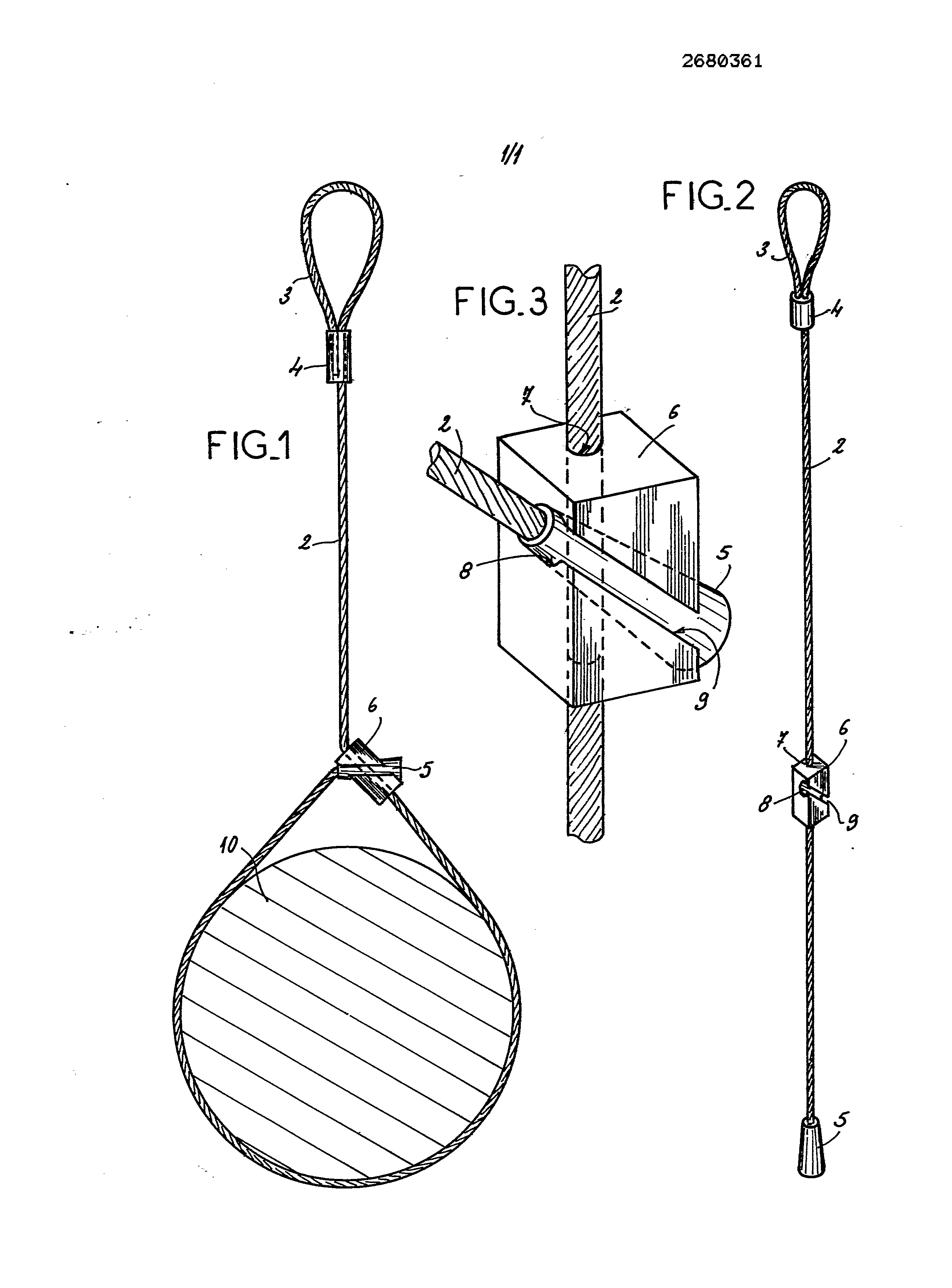
The present invention relates to a sling for single use for bundling and manipulation of elongated members. The elongate members, may be made in particular by bars, tubes, or flat bars. Such elements are often grouped for the transport and handling, as a burden. The components of the bundle are connected to one another by soft wire elements surrounding them, by points, and are each closed on themselves by twisting. The function of these links is simply join the components of a burden. However, it has been found that in many cases, these links were also used to handling of the bundle, with the elementary rules offending safety, since the resistance of the links is not adapted to receive the load caused by the lifting of such bundle. Therefore, the handling of a burden is to be performed with a sling specially adapted. Since it is a reusable sling, the safety value is to be of five for a booth, and six for handling on site. This means that the sling must be able to withstand loads of a value respectively five and six times higher than the value of the load resulting from the handling of the bundle. In the case wherein a sling can be used only once, the safety factor can be reduced to two. However, there is no solution disclosed for ensuring that the sling, theoretically intended for one-time use only, not used several times. Indeed, the currently known devices to avoid the opening of a sling by an insert thereon, after the sling has been placed around the burden. However, by not placing the security element for that the sling, theoretically to single use, may be re-used, with the risk of rupture causing accidental. The aim of the invention is to provide a sling with both bundling of elongated members, i.e. grouping thereof in the form of a bundle, and which also forms a sling for single use, the uniqueness of the use is provided by the structure of the sling. To this end, the sling as, comprises: -a cable, at one end of which is provided a loop, and secured to the other end thereof a sleeve, -and a lock piece comprising a through hole for engaging the cable and its free sliding thereon, and a notch which, through, on the one hand, in one of its side faces over the entire width thereof, by a slot of width at least equal to the diameter of the cable and, on the other hand, in the through hole, has a section substantially corresponding to the cross-section of the sleeve at one end of the cable. The cable of the sling is wrapped around the components of the burden to perform, the locking part is moved along the cable, such that the distance between it and the sleeve crimped at one end of the cable substantially corresponds to the circumference of the bundle. The cable, close to its end comprising the sleeve, is introduced laterally into the notch of the locking piece, after which, it is exerted a pull on the cable to allow the sleeve inside the said slot. During its movement of penetration within the notch, the sleeve bears against the portion of the cable at the through hole of the locking part. Manipulation of the sling and of the bundle associated therewith is carried out by means of the loop provided at one end of the cable. When a tensile force is applied to the loop, the force exerted on the cable penetration results in a more and more important a side face of the sleeve at the end of the cable in the portion of the cable at the through hole. As a result that, when the burden has been put back to the ground, it is practically possible to enhance the sleeve of the notch of the locking part, such that the only solution to disengage the sling of the bundle, of cutting the cable, which makes any subsequent use of the sling impossible. Advantageously, the sleeve affixed to one end of the cable has the general shape of a truncated cone, its end that faces the the middle of the cable having a smaller cross section than its end facing the outside. The truncated shape of the sleeve promotes the wedging action when traction is exerted on the cable. According to another feature of the invention, and to ensure a good directional distribution of the stresses exerted on the two parts of the cable which are concentrated in the locking piece, the axis of the recess in one of the faces of the locking part forms an angle with the axis of the through hole for the passage of the cable. Preferably, in the latter case, the angle formed by the axis of the recess in one of the faces of the locking part and the axis of the through bore, is of the order of 4-5 °, and the notch is shaped such that its end to receive the free end of the sleeve is on the same side as the end of the through hole for the passage of the cable, turned towards the end thereof equipped with the sleeve. In any case, the invention will be clearly understood with the aid of the description that follows, with reference to the appended schematic drawing representing, by way of non-limiting example, one embodiment of the present sling: Figure 1 is a perspective view of the sling in the closed position about a burden which has been coarsely schematized; Figure 2 is a front view of the sling in the open position; Figure 3 is a perspective view and of the locking piece of the sling, and that parts of the cable interacting with it in the closed position of the sling. The sling shown in Figure 1 comprises a cable 2, at one end of which is provided a loop 3 formed by folding the cable to itself, with closing of the loop by a crimped sleeve 4. At the other end of the cable can be attached a crimped sleeve 5, of frustoconical shape, the lower section of the sleeve being at its end that faces the the middle of the cable that at its other end. On the cable 2 is mounted, prior to attaching the sleeve 5, a locking piece 6. In the embodiment represented the pattern, the workpiece has a parallelepiped shape. However, this form might be different. The piece is made of metal, or plastic. It comprises a through hole 7 in, for engaging the cable 2 and its free sliding onto the cable. Inside of the locking part 6 is a recess 8 which opens into one of the side faces of the part, over the entire width of said face. The notch opens by a slot 9, the width of which is at least equal to the diameter of the cable 2, so as to allow a lateral introduction of thereof within the locking part 6 by the slot 9. The notch 8 also goes into the through hole 7. Furthermore, the cross-sectional area of the slot corresponds substantially to the cross section of the 5 sleeve crimped to one end of the wire, to allow engagement of the sleeve, from right to left, in the embodiment represented the pattern. As shown in particular in Figure 2, the axis of the notch 8 forms an angle with the axis of the through hole 7, this angle being of the order of 45°. Furthermore, the notch is shaped such that its end, to the right to the pattern, for receiving the free end of the sleeve, is on the same side as the end, located at the bottom to the drawing, of the through hole for the passage of the cable, turned towards the end of the cable provided with the sleeve 5. In practice, a burden of parts designated by the reference 10 to the pattern is surrounded by the cable, especially from the end thereof including the sleeve 5. The locking piece is moved along the cable so that its distance of the sleeve 5 substantially corresponds to the circumference of the bundle. The cable 2 is engaged by the slot 9 in the notch 8, near the crimp sleeve 5, after which, is exerted a pull on the cable to engage the sleeve 5 within the notch 8 into the position shown in Figures 1 and 3. During this movement, the sleeve 5 bears with high pressure against the portion of the cable located in the through hole 7, performing a lock. More the traction in the cable is important, which phenomenon occurs when the bundle is lifted, more the sleeve 5 comes "be printed" in the portion of the cable passing through the hole 7. In these conditions, upon manipulation of the burden, disassembly is approximately impossible in normal conditions, such that the only solution for removing the sling comprises cutting the cable at the loop that it forms around the burden 10. As apparent from the foregoing, the present invention provides a great improvement to the existing art by providing a sling simple design, for its closure about a burden without requiring attachment, or a specific tools, and providing a total safety of the closure, since the sling can no longer be removed after destruction. Since it is a matter of course, the invention is not limited to the single embodiment of the present sling described above example, on the contrary it embraces all variants. Therefore, in particular, that the shape of the locking part might be different, that the shape of the sleeve 5 might be different, or that the angle formed by the axis of the through bore and the axis of the notch could be different, without as much to the scope of the invention. This sling comprises: - a cable (2), at one end of which is arranged a loop (3), and at the other end of which is fixed an insertion component (5), - and a locking component (6) comprising a through-hole (7) or a groove enabling it to be engaged on the cable (2) and slid freely on the latter, and a notch (8) which, emerging, on the one hand, in one of its lateral faces over the whole width or length of the latter, through a slot (9) having a width which is at least equal to the diameter of the cable (2) and, on the other hand, in the through-hole (7) or in the groove, comprises a cross-section which corresponds substantially to the cross-section of the insertion component (5) fixed to one end of the cable. Application to the encircling and handling of metal bars or to the assembly of metal bars. <IMAGE> 1.-disposable sling for bundling and manipulation of elongated members, characterized in that it comprises: -a cable (2), at one end of which is provided a loop (3), and secured to the other end thereof a sleeve (5), -and a locking part (6) having a through hole (7) for engaging the cable (2) and its free sliding thereon, and a notch (8) which, through, on the one hand, in one of its side faces over the entire width thereof, by a slot (9) has a width which is at least equal to the diameter of the cable (2) and, on the other hand, in the through hole (7), has a section substantially corresponding to the cross-section of the sleeve (5) attached to one end of the cable. 2.-sling according to claim 1, characterized in that the sleeve (5) attached to one end of the cable (2) has the general shape of a truncated cone, its end that faces the the middle of the cable having a smaller cross section than its end facing the outside. 3.-sling according to any one of claims 1 and 2, characterized in that the axis of the notch (8) opening into one of the faces of the locking pieces (6) forms an angle with the axis of the through bore (7) for the passage of the cable. 4.-sling according to claim 3, characterized in that the angle formed by the axis of the notch (8) opening into one of the faces of the locking part (6) and the axis of the through bore (7), is of the order of 45 °, and the notch (8) is shaped such that its end for receiving the free end of the sleeve (5) is on the same side as the end of the through hole (7) for the passage of the cable, turned towards the end thereof equipped with the sleeve (5). SEPARATOR FOR SINGLE USE FOR BUNDLING AND HANDLING LONG ELEMENTS