PROCESS OF CORRECTION OF the DRIFT OF the SIGNAL Of a PRESSURE PICK-UP
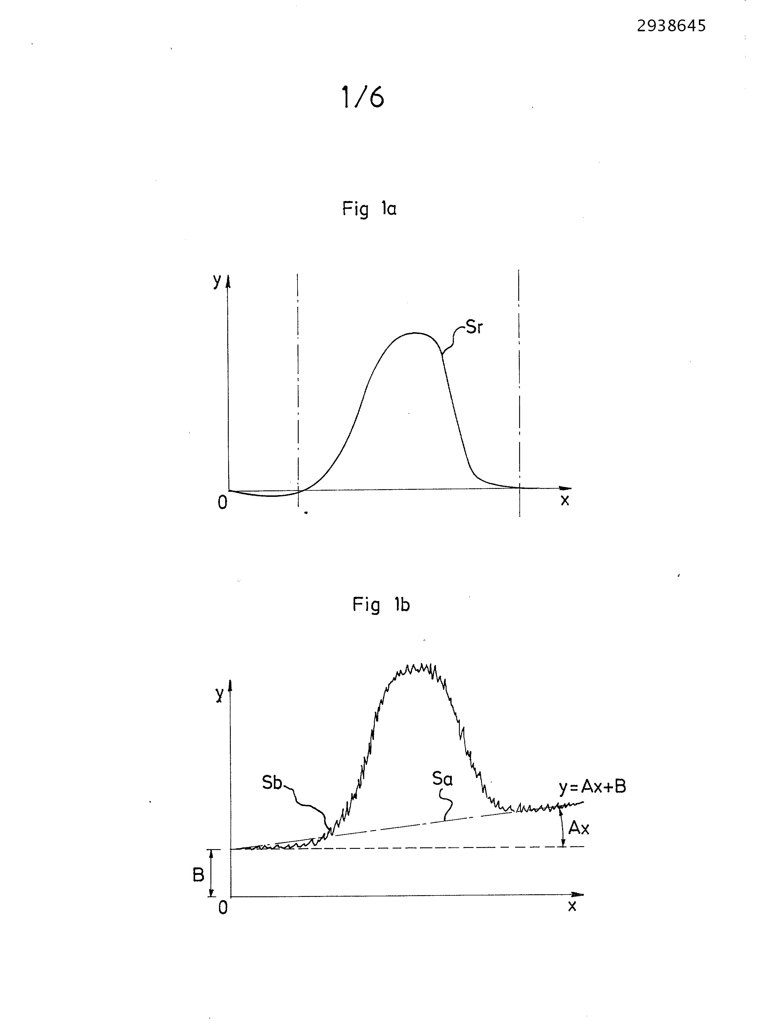
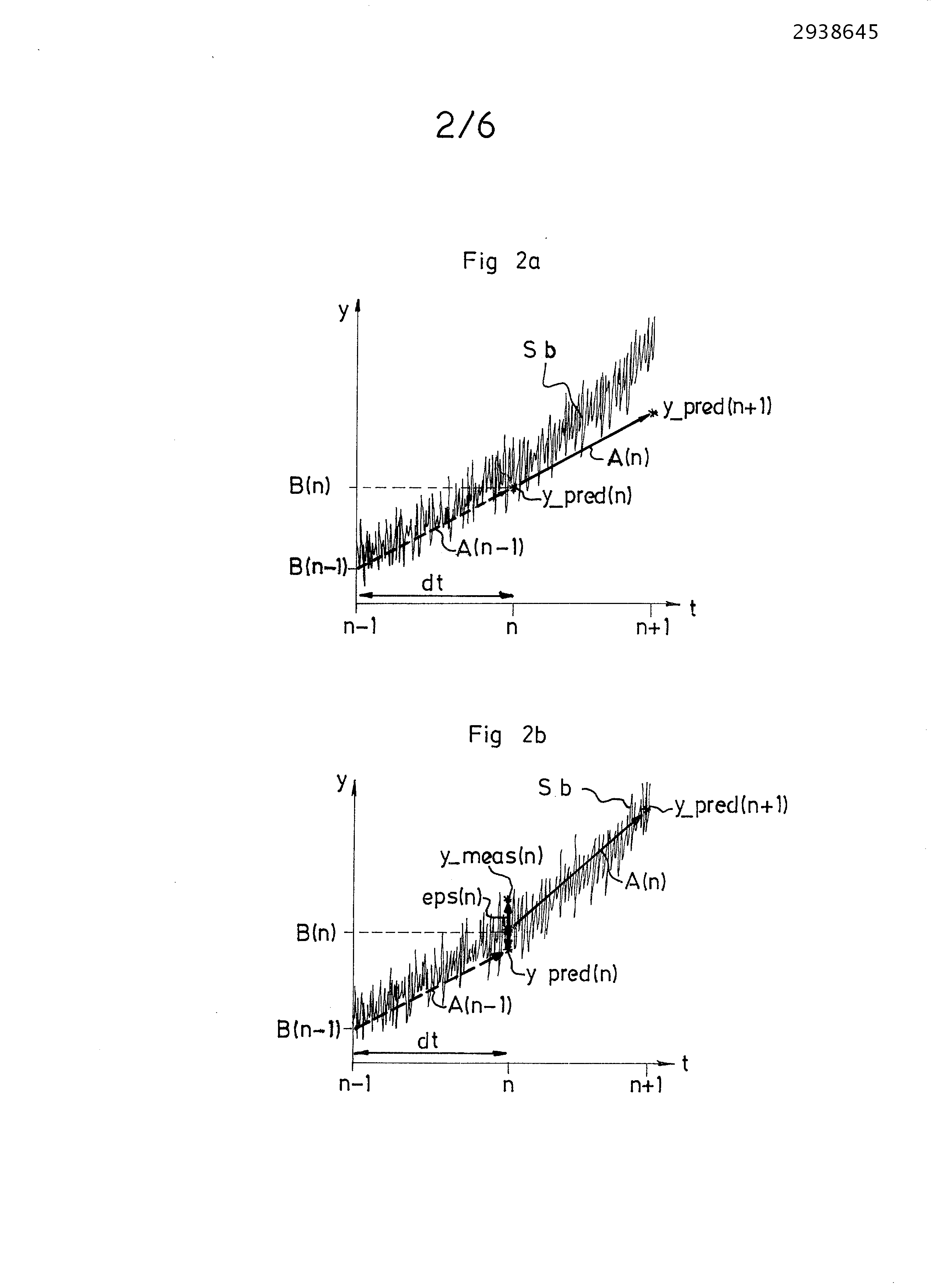
The present invention relates to a method of correcting the drift of the signal of a pressure sensor. It is particularly useful for the pressure sensors measuring the pressure in a cylinder of an internal combustion engine. Measurement of pressure in the combustion chamber of a cylinder of diesel engine is performed by a pressure sensor located, for example, in a glow plug. The curve yielding the pressure as a function of time during a cycle of the engine (intake, compression, combustion, exhaust) has a base signal most preferably straight and centred on zero, superposed periodically peaks of pressure. Such sensor is usually provided with a sensitive element piezoelectric. Because the operating environment of the sensor, it is exposed to temperature variations and pressure. In particular, temperature variations create the pyro-electricity in the sensitive element of the piezoelectric sensor, thereby changing the value of the pressure signal that it delivers. The curve yielding the pressure as a function of the output of the sensor is thus different from the actual pressure prevailing in the cylinder. Specifically: •the base signal is no longer centered on zero, i.e. the average pressure value measured is offset by a constant B. •the base signal is no longer parallel to the axis of the abscissa, i.e. horizontal, but has a slope A and is of the type Therefore, the base signal can be likened to a straight line of which the equation is of the type The base signal is therefore necessary to provide the motor computer actual pressure measurements and reliable, properly re-focused to zero (or on a predefined constant value) and without temporal drift. A processing algorithm needs to correct the signal provided by the sensor, i.e. it is to be useful for: •determining B, •determining A, •discriminate the peaks relative to the base signal drift, by determining the location and duration of pressure peaks. In effect, if the sudden increase in pressure due to the peaks is not treated independently of signal drift, compromised determining the slope A and the constant B, •subtracting the signal provided by the sensor, the base signal( The signal processing may be carried out either on signal acquisition and directly by the sensor, or after signal acquisition by an external microprocessor. The latter solution has the advantage that the treatment to be performed after the signal is acquired, with a means for calculating time required and available in a control computer-engine. This still has the disadvantage of overloading the memory size of the computer permanently. The direct treatment by the pressure sensor has many constraints: it is to be fast, accurate and limited in size memory used, since integrated in the sensor that does not have a strong integrated computer and provided with a large memory. Known is prior art, that the direct treatment of signal may be performed by estimating, according to the method of least squares, from a linear model on a sliding window containing points N points. The major drawback of such treatment is the size large memory which is then Other methods of treating the signal may be contemplated, such as using a Kalman filter for example. The filter is based on a recursive method error correction between a signal and its prediction attenuated by a gain. The prediction of the signal is calculated from the filtered signal and corrected at the time of previous measurement. However the applying such a method on a pressure signal comprising peaks at regular intervals has the following shortcomings: •if the correction is too large, then determining the slope A and the constant B is distorted since it is overestimated by the presence of the pressure peaks. •if the correction is low, the corrected signal does not take into account the error generated by the presence of peaks of pressure and is then close to the right The present invention proposes to determine the values of the slope A and the constant B and the pressure peaks reliably without the need for large memory size calculations. The achieves these goals with the aid of a method of correcting the drift of the signal of a pressure sensor for measuring the pressure in a cylinder of an internal combustion engine, the signal being available to a succession of points forming a base signal represented by a straight line equation •I: use of a fast Kalman filter, i.e. having gains constant slope and high values, for the detection of points belonging to peaks of pressure, •It: use of a Kalman filter slow, i.e. having gains constant slope and low values, for determining the slope and the constant of the straight line representing the base signal, •III: correction, for each point, the drift of the signal as a function of their membership or non-to the peaks detected pressure determined in step I and of the values of slope and the constant determined during step II. In a first embodiment, in step I, is: •estimates the prediction error on a point of the signal using the fast Kalman filter used, and • filter maximizes the standard deviation of the prediction error for estimating the stability of the point to the precedent claims, •determines the beginning and/or end of a peak pressure at this point. Advantageously, during step I, is determines the start of the peak pressure in a point according to at least one of the two following criteria: •the prediction error at that point is above a threshold peak start, maximized filtered and • the standard deviation of the prediction error at that point is above a threshold standard deviation peak start. Preferably, the threshold standard deviation peak start is the last minimum value of the standard deviation filtered and maximized, multiplied by a coefficient peak start. Furthermore, the end of the peak is determined at a point according to at least one of the two following criteria: •the prediction error at that point is below a threshold limit peak, •the standard deviation of the filtered and maximized in error point is below a deviation threshold peak type of the limit. Advantageously, the deviation threshold type of the limit of peak is equivalent to the last maximum value of the standard deviation filtered and maximized, multiplied by a coefficient peak end. In another embodiment, in step II is: •estimates the slope and the constant the right from the Kalman filter slow •replaces the points belonging to the peak pressure determined by the Kalman filter rapidly in the event of step I, by the points predicted by the Kalman filter using the slow slope and the constant previously estimated. In a further embodiment in step III, is subtracted from the signal from the sensor the right determined in step II. According to the invention, the gain of slope of the Kalman filter gain is greater than the slope of the Kalman filter slow constant and the gain of the Kalman filter is greater than the constant gain of the Kalman filter slow. In suitably, the gain of slope of the Kalman filter is lower than the gain constant of the filter Fast Kalman gain and the slope of the Kalman filter is lower than the gain constant slow the Kalman filter. The invention is also applicable to any signal correction device, the signal is suitable for a pressure signal, implementing the method having any of the preceding claims. Therefore, the invention applies to all pressure signal sensor comprising the signal correction device according to the invention. And the invention also relates to any electronic computer having the signal correction device according to the invention. Other features and advantages of the invention shall become apparent from the description that will follow by way of non-limiting example and for the examination of the accompanying drawings in which: •Figure 1a is a schematic representation of a curve of actual pressure in a cylinder of an internal combustion engine over time, upon compression, •Figure 1b is a schematic representation of a pressure curve in a cylinder of an internal combustion engine over time, upon compression, as delivered by the pressure sensor, •Figure 2a is a schematic representation of the application of a Kalman filter to a signal, without correction, •Figure 2b is a schematic representation of the application of a Kalman filter to a signal, with correction, •Figure 3a is a schematic representation of the Kalman filter is applied for a quick pressure signal, according to the invention, •Figure 3b is a schematic representation of the Kalman filter is applied for a slow to a pressure signal, according to the invention, •Figure 4 is a schematic representation of the application of a Kalman filter to the detection of pressure peaks, according to the invention, •Figure 5 is a schematic illustration of the signal processing according to the invention. A curve yielding the variation of the actual pressure Sr prevailing in the combustion chamber of a cylinder as a function of time is shown in Figure 1a. This curve is in the nature of a right centered on zero on which overlap peaks of pressure. For the purpose of simplification, a single pressure peak is represented in Figure 1a. Figure 1b represents the noisy signal Sb as measured and provided by the pressure sensor. Specifically: •the base signal Sa is no longer centered on zero, i.e. the average pressure value measured is offset by a constant B, •the base signal Sa is no longer parallel to the axis of the abscissa, i.e. horizontal but has a slope type: •the slope A and the constant B are not fixed in time and can then vary from cycle to cycle. Its Thus the base signal can be likened to a straight line of which the equation is of the type Sb The correction of the measured signal is therefore needed to achieve the signal representative of the actual pressure Sr prevailing in the cylinder. For this purpose, the treatment of subtracted signal at each point in the measured signal provided by the sensor and Sb, the right Figures 2a and 2b illustrate the application of a Kalman filter to a signal from the type The constant B to point n can then be calculated from the slope and the constant at point n-1, considering the time interval between the points and dt n-1 n: The prediction the signal at the point n+1 is: The Kalman filter is intended to compare at the point n, this prediction, with the measured actual value y_meas (n) the noisy signal Sb provided by the sensor, and then correcting the slope, A (n) and the constant at point n, B (n), so that the value of the predicted signal approximates the value of the signal Sb measured by the sensor. Therefore, the prediction error eps at the point n is thus: The correction is provided using a gain Ka which represents the attenuation of the desired correction with respect to the measured error. The parameters A and B thus corrected are used in the prediction formula (1) applied to the next point n+1 (Figure 2b). The invention proposes to use this method to the pressure signal to determine, reliably pressure peaks, the slope A and the constant B: •in a first step I:a first pair of high gain KaR , KBR is used for a filter said "fast", to obtain an estimate y_predR (n+1) y_meas close to the measured signal (n). Therefore increasing the slope, relative to the base signal Sa, due to a peak is detected quickly via the quick change of the values of slope AR and the constant Br (figure 3a). •in the second step II, a second pair of lower gains as those used for the filter "fast", KaL , KBL , is used for a filter said "slow", to obtain an estimate y_predL (n+1) closer to the base signal to extract. In this case, an increase in slope fast, y_meas shown by the point (n) is not taken into account in the prediction of the signal. The values of the slope Al and the constant BL , thus determined, are the correct values of the slope and the constant signal •finally, during the last step III, once pressure peaks determined during step I, and the values of the slope A and the constant B, determined in step II, the right Of course, the steps I and II take place simultaneously and the correction in step III is then immediate. The values of the gains KaR , KBR , KaL kB andL are between 0 and 1 and preferably the gains of slope are less than the respective constant gains. By applying the equations (1), (2), (3), (4) for each of the filters, is thus obtained in the following equations, for the fast filter: And for the filter slow: It is understood that the parameters A (n), (n) B, y_pred eps (n) and (n) are specific to each of the filters, because they do not the same level of correction. As shown in Figures 3a and 3b, the corrected points obtained via the two filters, y_predR (n+1) y_pred andL (n+1) are different. According to the invention and shown to the graphs annotated 4a and 4b of Figure 4, the Kalman filter is used for the detection of pressure peaks. Eps The prediction errorR (n) previously determined by the Kalman filter rapid provides an indication of the stability of the gradient of the signal and thus on any rapid change in slope. A peak of pressure of the noisy signal Sb is represented by a build-up, stabilization, and then a descent. Therefore, for a peak pressure, the prediction error epsR is a signal comprising two peaks, representing the mounted a positive peak pressure, and a negative peak representing the descent, (see Figure 4a). However the presence of background noise in, before or after the peak pressure also generates a peak (positive or negative) of the signal of the prediction error epsR . Therefore the signal is a succession of positive and negative peaks. The determining the peak pressure in its entirety through the prediction error signal is thus impossible. In the step I, the invention provides for the following additional steps for detecting, the pressure peak in its entirety: •The square of the prediction error epsR is used, the signal epsR 2 thus has two positive peaks to represent a peak pressure (see Figure 4a). The determining the peak pressure in its entirety is unfortunately not possible with this signal. Indeed, this signal passes still zero, making impossible the use of criteria of the amplitude of the signal to determine the duration of the peak pressure. •to obtain a signal not passing through zero, the square of the prediction error epsR 2 , or standard deviation, is filtered eps_sigma_filt : A coefficient Kys For this filtering is applied. For example Kys = 0.5. Furthermore, to ensure that the start of peak is detected quickly, the filter is applied only once the peak passed, thereby providing a signal comprising: •the square of the prediction error epsR 2 for the rise of the peak, •then the filtered signal of the square of the prediction error eps_sigma_filt to lowering said peak. The signal is taken the maximum of these two values over the duration of the peak. Hence, a maximized eps_sigma filtered signal equivalent to: Therefore, for detecting the beginning of a peak pressure, at least one of the following two conditions are applied: •when it is established that the measured signal is greater than the predicted signal to which is added a constant: •and if the standard deviation filtered maximized eps_sigma , defined by the equation (6) is greater than a threshold standard deviation start of peak eps_sigma_S1, then the beginning of the pressure peak is detected, otherwise the peak pressure has not started. The threshold standard deviation start eps_sigma_S1 peak is selected such that it has value for the last minimum value of eps_sigma , i.e. the value of eps_sigma at the beginning of the pressure peak eps_sigma_min (cf Figure 4b), multiplied by a coefficient peak delta2_up start. That is With Also, for the detection of end of peak, at least one of the following two conditions are applied: •if the measured signal is smaller than the predicted signal to which is added a constant: which is equivalent to •and if the standard deviation maximized eps_sigma filtered; defined by the equation (6) is below a threshold standard deviation end of peak eps_sigma_S2, then the end of the peak in pressure is detected, otherwise the pressure peak is not completed. The deviation threshold type of the limit of peak eps_sigma_S2 is selected such that it is the last maximum value of eps_sigma , i.e. the value of eps_sigma at the top of the peak pressure eps_sigma_max (see figure 4b), multiplied by a coefficient peak delta2_down end. That is With For any point n, it is possible to determine whether it belongs to a peak pressure or not. Generally, the value of the coefficient start delta2_up peak is between 0 and 10, the value of the coefficient of delta2_down end of peak is between 0 and 1, and the values of the start threshold delta1_up end peak and peak delta1_down are between 0 and 5 volts. Therefore, for each point n, if a peak is detected at that point, then the value of that point y_predR (n) cannot be selected for the estimation of the gradient constant A and B, but if a peak is not detected at that point, then the value of the point can be selected for the correct estimate of the slope A B and the constant. In the step II, determining the slope A and the constant B according to the invention, is produced by means of the Kalman filter slow. Indeed: •the slope and the constant average are estimated via the Kalman filter gains with low KaL kB andL , in order to provide correction slow, less influenced by the changes of the signal, i.e. relatively independent of the pressure peaks, and thus representative of the base signal •the points n are then predicted using the slope AL , and the constant BL previously computed at point n-1, •in the case where a peak has been detected previously to a point n via the fast Kalman filter, the value of this point y_predR (n) is replaced by the value of the predicted point by the Kalman filter slow y_predL (n). The peak pressure is thus replaced by a signal of a constant pitch, i.e. by a straight line. This prediction is required so that the determination of the slope AL and the constant BL , is not distorted by the presence of the peak pressure. To improve the accuracy of the values of slope AL and the constant BL , this step II may include variants. Indeed, if the start of a peak is detected, the value of y_predR (n) can be replaced by the value predicted by the Kalman filter slow or n-2, point c ' e. y_predL (n-2). This to accommodate the increase start low peak overestimates not the value of AL b andL . Also, to avoid sub-estimate the values of AL b andLi at the end of the peak, the value of y_predR (n) is replaced by the value predicted by the Kalman filter slow or n-1, point c ' e. y_predL (n-1). In the final step III, the right, The individual steps of the signal processing according to the invention are illustrated in Figure 5, having 5 graphs annotated 5a, 5b, 5c, 5d and 5th. Figure 5a is the signal measured by the sensor, comprising two pressure peaks and signal drift-type base: y= Figures 5b and 5c illustrate treatment the signal during step I: •Figure 5b represents the prediction error epsR the measured signal, •Figure 5c represents the standard deviation of the prediction error filtered maximized eps_sigma , and the values eps_sigma_min and eps_sigma_max. The step II is illustrated in Figure 5d. The basic signal y_predL obtained by the Kalman filter slow, is represented, in which the peak pressure obtained by the Kalman filter are replaced by straight lines. The figure 5th D represents the detection zone of the two peaks, as well as the base signal y_predL thus determined by carrying out the step III. The invention thereby determines the slope A, the constant B and pressure peaks reliably without the need for large memory size since the method is recursive order and predictive 1, a point n to a point n+1 and does not require the management and the storage over a long window of several points to apply the known formulas least squares. This method can thus be integrated in a cylinder pressure sensor or in the engine control. Of course, the invention is not restricted to the embodiment described and shown which has been given as example and may, for example be applied to any measurement signal comprising peaks. A method for correcting the drift of the signal from a sensor measuring the pressure in a cylinder of an internal combustion engine, the signal being comparable to a straight line of equation y=A×x+B, on which signal are overlaid pressure spikes, the correction method includes: I: using a rapid Kalman filter for detecting the points belonging to the pressure spikes, II: using a slow Kalman filter for determining of the slope (A) and of the constant (B), III: correcting, for each point, of the drift of the signal according to whether or not they belong to the detected pressure spikes determined during step I and the values of the slope and constant determined during the step II, wherin, during step I: the prediction error (epsR) on a point of the signal is estimated using the rapid Kalman filter, the standard deviation of this prediction error (eps sigma) is filtered and maximized, the start and/or end of a pressure spike at this point is determined according to at least one of the following two criteria: the prediction error (epsR) on this point is above a spike start threshold (delta1_up), the filtered and maximized standard deviation of the prediction error (eps sigma) on this point is above a spike start standard deviation threshold (eps_sigma_S1). 1. A method of correcting the signal drift (Sb) of a pressure sensor for measuring the pressure in a cylinder of an internal combustion engine, the signal being available to a succession of points forming a base signal (Sa) represented by a straight line equation •I: use of a fast Kalman filter, i.e. gains having slope (KaR ) and constant (KBR ) of high values, for the detection of points belonging to peaks of pressure, •It: use of a Kalman filter slow, i.e. gains having slope (KaL ) and constant (KBL ) of low values, for determining the slope (A) and the constant (B) of the straight line representing the base signal, •III: correction, for each point, the drift of the signal as a function of their membership or non-to the peaks detected pressure determined in step I and of the values of slope (A) and the constant (B) determined during step II to determine the actual signal (Sr) of the pressure in the cylinder. 2. A method according to claim 1 characterized in that during step I: •estimates the prediction error (epsR ) on a point of the signal using the fast Kalman filter used, and • filter maximizes the standard deviation of the prediction error (eps_sigma) to estimate the stability of the point to the previous points. •determines the beginning and/or end of a peak pressure at this point. 3. A method according to claim 2, characterized in that, during step I, is determines the start of the peak pressure in a point according to at least one of the two following criteria: •the prediction error (epsR ) at that point is above a threshold peak start (delta1-up), maximized filtered and • the standard deviation of the prediction error (eps_sigma) at that point is above a threshold standard deviation start of peak (eps_sigma_S1). 4. A method according to claim 3, characterized in that the threshold standard deviation start of peak (eps_sigma_S1) is equivalent to the last minimum value of the standard deviation filtered and maximized (eps_sigma_min), multiplied by a coefficient peak start (delta2_up). 5. A method according to claim 4, characterized in that the value of the start of peak coefficient (delta2_up) is between 0 and 10. 6. A method according to any one of the preceding claims, characterized in that during step I the end of the peak is determined at a point according to at least one of the two following criteria: •the prediction error (epsR ) at that point is below a threshold limit peak (delta1_down), maximized filtered and • the standard deviation of the error (eps_sigma) at that point is below a deviation threshold type of the limit of peak (eps_sigma_S2). 7. A method according to claim 6, characterized in that the threshold standard deviation (eps_sigma_S2) peak end is the last maximum value of the standard deviation filtered and maximized (eps_sigma_max), multiplied by a coefficient peak end (delta2_down). 8. A method according to any one of the preceding claims, characterized in that in step II is: •estimates the slope (A) and the constant (B) of the right from the Kalman filter slow, •replaces the points belonging to the peak pressure determined by the Kalman filter rapidly in the event of step I, by the points predicted by the Kalman filter using the slow slope (AL ) and the constant (BL ) previously estimated. 9. A method according to any one of the preceding claims, characterized in that in step III, is subtracted from the signal from the sensor the right predicted 10. A method according to any one of the preceding claims characterized in that the gain of slope of the fast Kalman filter (KaR ) is greater than the slope of the gain Kalman filter slow (KaL ). 11. A method according to any one of the preceding claims, characterized in that the gain of the Kalman filter constant fast (KBR ) is greater than the constant gain of the Kalman filter slow (KBL ). 12. A method as claimed in any one of the preceding claims, characterized in that the gain of slope of the fast Kalman filter (KaR ) is less than the constant gain of the Kalman filter fast (KBR ). 13. A method according to any one of the preceding claims, characterized in that the gain of the Kalman filter slow slope (KaL ) is less than the constant gain of the Kalman filter slow (KBL ). 14. Correction device a signal implementing the method according to any one of the preceding claims. 15. Device according to claim 14 characterized in that the signal is a pressure signal from a cylinder of an internal combustion engine. 16. Sensor pressure signal comprising the signal correction device according to claim 14. 17. Electronic computer that includes the signal correction device according to claim 14.