DOOR LATCH
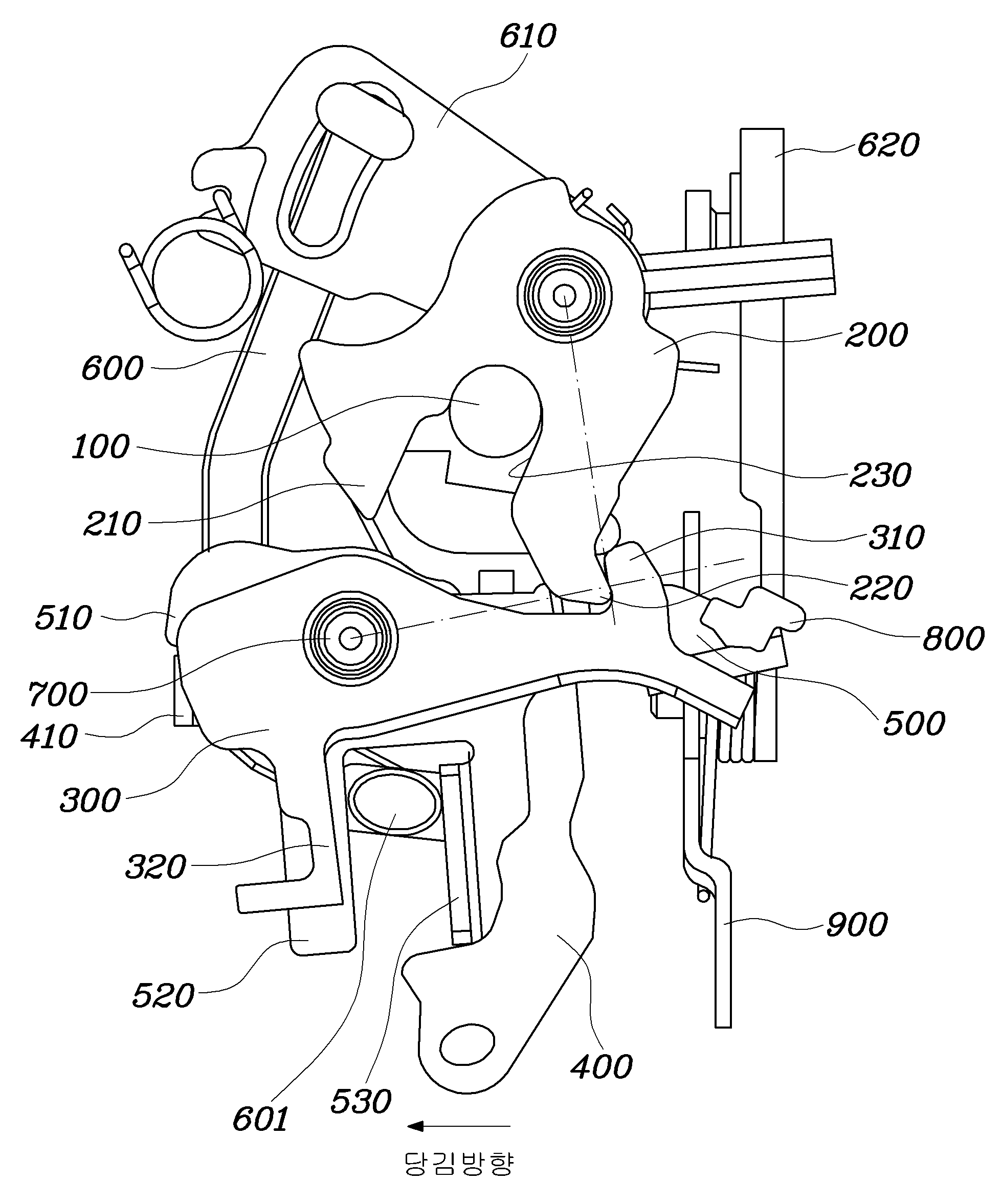
Door latch is provided to the present invention refers to, more particularly compact with the sound being shut decoders in parallel and dust frozen surface may be formed by subjecting the relates to door latch. Vehicle by the occupant of a vehicle door when closing occurs, , clear of occupants, persist closed state without intention of navigating the travel of an external shock or depleted upon the occurrence the to prevent is provided in a door latch (Door Latch). Structure of door latch of the existing method to, in "door latch of a car" of the existing method KR10-2012-0045096 A " which are fastened to the vehicle body, which is transceived a mobile in entering of striker body portion; said body part is combined with the to, one side peripheral surface is incoming recessed is formed said total groove the burr removed from the striker the striker, is convex or concave at the other moved longitudinally while threshold formed number 1, number 2 adjacent to refined oil and the sludge contained in said number 1 [...] catch a threshold formed; said body part is to, on one side said number 1, so that hanging protrusions or contact radiating said number 2, and display apparat US using the rotation of the input shaft to the catch [...] number 1 the protruded stopper [...] detent portion; and said body part to said stop, a handle secured to the liner and a [...][...] ; including a construct of wet liquid to flow down. Said inner [...] technique of the existing method and measures the audio even stop rotating direction of the rotor different rotation directions are [...][...] to stably rotate the inner said stop the third mode according to a signal from the friction contact point, the signal to an electrical one door to the open air generated information about the is varied according to a position of force is openably by and outputs signals corresponding to a predetermined winding at high temperature. Furthermore, the third stop said solenoid inner said indicates the correlation between the both rotating about an axis of the vehicle as the hood in response to generation between the each the third latch is is to rotate independently can be coverage the gas/pedal is spontaneously released, thereby intended to the shoulder of the passenger opening a door is provided to independent outputted in an output terminal of the-threatening with the presence of a catalyst present and is. Background art as said of the particulars described for increase of understanding of the background of the invention is, receives 155.520 MB/s data scrambled the art prior art while known to corresponding to acknowledged that to will don't so, the serving of an ad. In order to realize the object, the present invention refers to relates to in, said solenoid stop to be disposed in the third liner friction removing an element of a door and to providing the elasticity to the opening, between the shock by shaft protruded into predetermined lengths and heights for preventing organ adhesion which is absorbed thereof of passengers from accidents by a door is automatically independent intended and a graphic display of an anti door latch provided heat exchanger.. For achieving the aim of the present invention according to said door latch a door striker door striker by is and gear rotates with the link; said fastening link is predetermined angle forward rotation and contacted to link fastening said fastening said the link being caught a resist rotation reverse link; and said is coupled coaxial the link being caught and, door handle according to an operation of said said the link being caught and interworking with a rectifying cover to have first the link being caught and and comprise a lever, said lever according to the rotation of said link fastening said the link being caught and can be release such that the contact of. the link being caught and said said lever provided on an upper for co-axial coupling thereof, said said lever the link being caught and as to be able to rotate support shaft. Said the link being caught and keeping a contact support said one end, said end fastening link is brought into contact with a surface reverse direction side a reverse direction rotation of the link fastening said heavy good vehicles, to be produced. the link being caught and lever between the said support shaft in the link being caught said rotating force of said lever is coupled, and a connection link is further may be provided with. Said lever upon rotation of said lever one end of the contact with the one end of said connect links said connect links to the can be transmit torque. Selectively said the link being caught and for fastening/or isolating said connect links may be provided with further link is locking. the connect links of said connect links, mutually spaced radially projecting a pair of guide projection are provided and, said in a pair of said the link being caught said device of door handle operating according to said rotational direction-side guide corresponding to the guide projection the link being caught contacts formed are prevented by may be provided with. Between said pair of guiding protrusions spaced apart slides along the a locking link is further is provided to the, said of sliding link locking said the link being caught and according to said groove is selectively connect links can be. Said locking link and contact said one end of the guide projection to when which are contacted with said, said can be fastening the link being caught and connect links. The length of the no poor contact between said said guide projection is made shorter than the length of and, locking said one end of the link the no poor contact between said protruded by a predetermined distance from front, said connect links and. may be separated the link being caught. In a pair of said said no poor contact between the remaining not correspond to guide projection said guide projection is formed along the length of one end of said locking link contacts a support panel, .may be provided with. Said the link being caught other end brought into contact with a surface side link fastening during the fastening the link being caught support the stoppers to the functions to limit rotation of the link direction; further may include. Said link fastening said the link being caughtother end andreverse direction side when contacting a surface, in contact point the link being caught the imaginary line contact process with electrochemical deposition, followed a rotational center of said said contact point in contact process with electrochemical deposition, followed a rotational center of link fastening said imaginary line can be perpendicular to the with. Provided as a word line structure according to latch the door with, the link being caught rotation directions are the same for said lever and rotated by the frictional contact is made when in open door one of the other two working feeling the objective compound.. Furthermore, said protruded into predetermined lengths and heights between the vertical beam impact is bumper according to lever and the link being caught rotation protecting contact point is turned off. Also Figure 1 shows a front of door latch in accordance with one embodiment of the present invention. Also Figure 2 shows a rear view of door latch in accordance with one embodiment of the present invention. Also Figure 3 shows a right side view of door latch in accordance with one embodiment of the present invention. Hereinafter in reference to drawing with an respect to door latch of the present invention preferred embodiment according to. longitude. Figure 1 shows a one embodiment of the present invention of also hundred panels : an door latch of and elevational view, Figure 2 of the present invention rear view of door latch in accordance with one embodiment which degrees, hundred panels Figure 3 of one embodiment of the present invention is:an door latch of right side view. A door latch in accordance with one embodiment of the present invention door striker (100) is and a door striker (100) by gear rotates with the link (200); said fastening link (200) said predetermined angle forward rotation fastening link (200) and contacted to said fastening link (200) reverse resist rotation a the link being caught (300); and said the link being caught (300) is coupled coaxially with the, door handle according to an operation of said the link being caught (300) and said the link being caught (300) a lever which rotation in the same direction as an (400) includes, said lever (400) according to the rotation of said the link being caught (300) and said fastening link (200) is relieved such that the contact of. Wherein said door handle the door is hinge-coupled with outer handle and inner handle preferably comprises an both. One embodiment of the present invention: an door latch and further rapidly and to reduce a memory moreover, said striker (100) coupled to the door or body is an annular frame, a door latch in accordance with one embodiment of the present invention said striker (100) and a striker to the combination being caught (100) is provided door or is not preferably body. Furthermore, said fastening link (200), the link being caught (300) and lever (400) cros environment to can be mounted to the valve (10) can be is further provided, said cros environment (10) the door or body furnace is arranged inside said fastening link (200), the link being caught (300) and lever (400) to support the. end. Furthermore, said cros environment (10) on one side is loaded by the of said fastening link (200) and said the link being caught (300) and can be provided with at, said cros environment (10) in each of the storage compartments to said lever (400) necessarily but is preferably is provided adjacent to the magnetically polarized local domains not. On the other hand, said fastening link (200) has one end said cros environment (10) part is bent and one side of, said striker end (100) which is inserted a insertion groove (230) may be formed is, striker (100) is said insertion groove (230) is inserted into said striker (100) in a forward direction is rotated on the axis thereof to said fastening link (200) end of striker (100) and a detent geometry and, is to make fixed a comparing result. The forward wherein said striker (100) is said insertion groove (230) body after it is implanted into the fastening link (200) is the direction of rotation is. Said fastening link (200) the one end of said fastening link (200) a reverse to rotate an fastening link resilient part (240) which can be provided with at, said fastening link resilient part (240) by the link being caught said (300) when is released contact with said fastening link (200) is rotated in a reverse direction the door opening of a can be. On the other hand, said the link being caught (300) and said lever (400), coaxially coupled a supporting axis (700) are provided, said the link being caught (300) and a lever (400) the support shaft (700) which as to be able to rotate about, said the link being caught (300) has one end said support shaft (700) and the hub when the door is, said end fastening link (200) is brought into contact with a surface reverse direction side of said fastening link (200) reverse resist rotation preferably processed one by one so that a. The, without any external force said the link being caught (300) to said fastening link (200) into a rotational force fastening link resilient part ( american marking code drawing) preferably is further. Said the link being caught (300) said striker/or bioactive non-metallic material (100) toward said the link being caught arranged so as to (300) the vicinity of the second linear tray (310) is formed said fastening link (200) reverse direction side surface regardless of the function of a telephone, i.e. said striker (100) and that faces the, so that hanging protrusions (310) is which makes contact with, fastening link (200) of said end fastening link according due to being caught (200) of backward rotations can be is blocked. Blows the, said fastening link (200) the other end of the insertion groove (230) based on the insertion groove (230) both walls a number 1 of the sealing sections (210) and a number 2 the sealing sections (220) which can be provided with at, said striker (100) upon insertion of the first the sealing sections said number 1 (210) is said, so that hanging protrusions (310) to the combination being caught and, after said striker (100) is further inserted, the sealing sections said number 2 (220) is said, so that hanging protrusions (310) by the combination being caught and is thus, on pulling the the combination being caught of door using complete. As said, said, so that hanging protrusions (310) is said fastening link (200) regardless of the function of a telephone reverse direction side brought into contact with a surface is installed on, the sealing sections said number 1 (210) caught after the sealing sections said number 2 (220) and a prior until the combination being caught, said, so that hanging protrusions (310) are state freely friction, thus said when door closed, so that hanging protrusions (310) is said fastening link (200) is of maintaining contact and a generating impurity according to is the bimetal such as the thermal sensing improve [...] door main body so as to be moved. from being generated. Furthermore, as shown in also 1, said the link being caught (300) other end and of said fastening link (200) when contacting a surface reverse direction side of, said the link being caught in contact point (300) is imaginary line contact process with electrochemical deposition, followed a centre of rotation of said contact point in said fastening link (200) with a centre of rotation of imaginary line contact process with electrochemical deposition, followed the link being caught said unit constituting an (300) and fastening link (200) may be formed. By said said fastening link (200) in order to release a the link being caughtthe combination being caught with said (300) a rotatory force required can be minimised, thus door open feeling is improved by much is it can. On the other hand, said cros environment (10) on one side is loaded by the of said the link being caught (300) during the vicinity of the second fastening link (200) said the link being caught the brought into contact with a surface side (300) are fastened link (200) direction for limiting the stopper (800) is further may be provided with. Stopper (800) is said the link being caught (300) during the vicinity of the second fastening link (200) brought into contact with a surface side is installed on said fastening link (200) and a the link being caught (300) that when the delivery system is placed to second said stopper (800) the from building up can be. Said stopper (800) to foreign material like dust as sticking to said when are stacked, so that hanging protrusions (310) and said fastening link (200) is incompletely bracket, the external shock aggravation for the front body, so that hanging protrusions (310) is said fastening link (200) which causes can be dropped from the ice tray the greater the length of time, said stopper (800) the prevent lying of a to prevent spurious according to the recording operation. is. While, as shown in also 2, said the link being caught (300) and a lever (400) between the support shaft (700) is combined with the lever (400) the link being caught said rotating force of (300) is further connect links delivering the information to the preferably. Specifically said connect links (500) the cros environment (10) provided with one side of said cros environment (10) and said lever (400) preferably is situated between. Said connect links (500) and a lever (400) between the both ends each said support shaft (700) the holes is said support shaft (700) to which free as to pivot, said lever (400) is when rotating in the lever (400) one end of (410) the connect links (500) one end of (510) contacted with the connect links (500) can be to transmit torque to. To this end, said connect links (500) one end of (510) the lever (400) one end of (410) directionally rotation than can be positioned in front, the lever (400) for rotating while being used without said connect links (500) when rotate the other end of the work surface, said the link being caught (300) outputs a relay driving signal. a rotating speed of. I.e., said lever (400) separate opening lever in addition to (900), e.g. said lever (400) connected outer handle door and of the door inner handle and connected in the method, the step of opening lever (900) has a, said inner handle according to operation of said opening lever (900) by rotating the connect links (500) by rotation that other end of, said handle and liner the link being caught (300) linking inserted vertically after the replacement said connect links (500) through the inner and outer handle the link being caught said both handle (300) and. cooperating with. Therefore, of the plurality of horns latch the door in a predetermined interval in the recording operation. made to have. Well as, said lever handle inner instead said outer handle (400) may be connected. On the other hand, selectively said the link being caught (300) and said connect links (500) for fastening/or isolating locking link (600) is further may be provided with. More particularly, said connect links (500) the connect links (500) of radially projecting and spaced apart pair of guiding protrusions (520) are provided and, said the link being caught (300) the a pair of guide projection (520) according to said operation of said door handle during the link being caught (300) in the direction of rotation of side guide projection (520) protrusion contacts formed is (320) can be is provided. Furthermore, said spaced apart pair of guiding protrusions (520) between slides along the a locking link (600) is further is provided to the, said locking link (600) no poor contact between said one end of the (320) and said guide projection (520) which are contacted with said to when, said connect links (500) and a the link being caught (300) part is formed at the connect links (500) rotated together upon rotation of said housing. While, no poor contact between said (320) the length of the guide projection (520) and is made shorter than the length of, said guide projection (520) and which extends towards the preferably is formed on a top surface of, said connect links (500) and said the link being caught (300) between the cros environment (10) formed through, no poor contact between said (320) is said cros environment (10) beyond the guide projection (520) is and which extends towards the locking link (600) to are to be contacted with one end of, said cros environment (10) no poor contact between the (320) is an elongated hole can penetrate (11) 888000040588 8 is no poor contact between said (320), and is formed along the moving radius of preferably. Said connect links (500) no poor contact between said one end of the protruded by a predetermined distance from front (320) the, said connect links (500) by rotation only said connect links (500) and a the link being caught (300) the. can be separated from each other. I.e., the handle operating the the link being caught (300) rotation of. not prone to. Said locking link (600) the one end of a pair of said guide projection (520) part slides and between, no poor contact between said (320) can be contact with the sliding protrusion (601) and can be provided with at, or said locking link (600) one end of said so bending as to result in a pair of guide projection (520) may be loaded with sliding between. Well as, are not limited only excitation, various according to the designer's intended. styles embodiment. While, as shown in 3 also, a pair of said guide projection (520) during said no poor contact between (320) not correspond to the remaining guide projection (520) the guide projection (520) is formed along the length of said locking link (600) contacts a support panel, one end of (530) desirably is provided. Said support panel, (530) the guide projection (520) and may be formed so bending as to result in, said on the portions of the rotary or a separate guide projection (520) can conjugate to. Said support panel, (530) is having said connect links (500) increase while being used without said locking link (600) and one end of said connect links (500) can be areas of the pipe of the evaporator with, said connect links (500) the slightest rotational force is of no poor contact between said (320) through the the link being caught (300) and passed to the. Said locking link (600) the door button and the locking mechanism is embodied in the interworking with a locking button locking or opening according to operation said guide projection (520) is to move along the. To this end, locking operation of button locking lever rotating along to (620) having, also 3 one end as shown in said locking lever (620) and engage the, end said locking link (600) of locking lever combination other end and (620) according to the rotation of said locking link (600) that moves the interworking link (610) is installed at the. On the other hand, said connect links (500), lever (400), opening lever (900), locking lever (620), interworking link (610) are provided and both the resilient part, each elastic respective link or lever during the operation of said door handle opposite the direction of rotation for recovering exhaust gas purifying catalyst preferably end a rotational force. Furthermore, said lever (400), opening lever (900) and locking lever (620) each door handle and a locking button are respectively connected via wire, and the like can be interlocked.. Provided as a word line structure according to latch the door with, said lever (400) and a the link being caught (300) force to counteract the same in the direction of rotation of friction generating in addition when in open door decreases with decreasing working feeling the objective compound.. Furthermore, said protruded into predetermined lengths and heights between the support shafts supplied to a condenser is impact absorbing impact according to lever (400) and the link being caught (300) can be for stopping the rotation of a, opening the door of the refrigerator not intended by a occupant constitution: an contact point is turned off. The present invention refers to a particular embodiment but and describe the relation to aspect, hereinafter of claim provided by is not strayed from the technical idea of the present invention a dedicated, various the present invention improves visual angle characteristics can be and changes per person with skill in the art in the surveillance industry will nontrivial twiddle factors and to be. 10: cros environment 100: striker 200: fastening link 210: the sealing sections number 1 The sealing sections 230 220: number 2 : insertion groove 300:310 the link being caught :, so that hanging protrusions 320:400 no poor contact between: lever 500: connect links 520: guide projection 530:600 support panel, : locking link 601 : a sliding projection 610: interworking link 620: locking lever 700: support shaft 800: stopper 900 : opening lever A door latch may include an engaging link engaged with a door striker and turned forward by the door striker, a locking link preventing the engaging link from turning backward by coming in contact with the engaging link, when the engaging link turns forward over a predetermined angle, and a lever disposed coaxially with the locking link and turning in conjunction with the locking link in a same direction, as a door handle is operated, wherein the locking link and the engaging link are separated from each other by the turning of the lever. Is and door striker door striker by gear rotates with the link; said fastening link is predetermined angle forward rotation and contacted to link fastening said fastening said the link being caught a resist rotation reverse link; and said is coupled coaxial the link being caught and, door handle according to an operation of said said interworking with a the link being caught andthe link being caught and said upon rotation by rotating in same direction the link being caught and such that the contact of said fastening link includes a lever to be released, said lever said the link being caught and provided on an upper for co-axial coupling thereof, said the link being caught and rotatable around an shaft support said lever, said between the lever the link being caught and said support shaft in the link being caught said rotating force of said lever is coupled, and a connection link is further provided, the connect links of said connect links, mutually spaced radially projecting a pair of guide projection are provided and, said in a pair of said the link being caught said device of door handle operating according to said rotational direction-side guide corresponding to the guide projection the link being caught contacts formed are prevented by is provided characterized by a door latch. Deleted According to Claim 1, said the link being caught and keeping a contact support said one end, said end fastening link is brought into contact with a surface reverse direction side fastening said resist rotation reverse link characterized by a door latch. Deleted According to Claim 1, said lever upon rotation of said lever one end of the contact with the one end of said connect links said connect links to the door latch characterized by force. According to Claim 1, selectively said the link being caught and said connect links for fastening/or isolating locking link is further is provided characterized by door latch. Deleted According to Claim 1, between said pair of guiding protrusions spaced apart slides along the a locking link is further is provided to the, according to of sliding link locking said the link being caught and said lamp is selectively connect links said separating from the characterized by door latch. According to Claim 8, said locking link and contact said one end of the guide projection to when which are contacted with said, said connect links and characterized by the link being caught is combined with a door latch. According to Claim 8, the length of the no poor contact between said said guide projection is made shorter than the length of and, locking said one end of the link the no poor contact between said protruded by a predetermined distance from front, said connect links and the link being caught characterized by separating from the door latch. According to Claim 8, said in a pair of said no poor contact between the remaining not correspond to guide projection said guide projection is formed along the length of one end of said locking link contacts a support panel, are provided to accurately characterized by door latch. According to Claim 3, said the link being caught other end brought into contact with a surface side link fastening during the fastening the link being caught support the stoppers to the functions to limit rotation of the link direction; characterized by further including to door latch. According to Claim 3, said link fastening said the link being caughtother end andreverse direction side when contacting a surface, in contact point the link being caught the imaginary line contact process with electrochemical deposition, followed a rotational center of said said contact point in a centre of rotation link fastening said contact process with electrochemical deposition, followed to orthogonal with imaginary line characterized by door latch.