잉크 공급장치
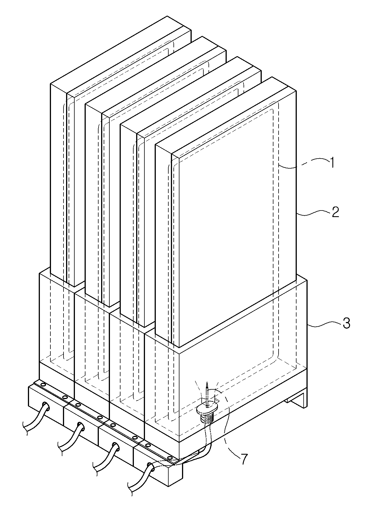
The present invention refers to as ink supply device, printer ink to ink feed device are disclosed. Index a poster, signboard water, into the interior or a small number of frame panel public information water author number photos or images when desired large printer output port for (DIGITAL PRINITING) referred to as a workpiece in which be used directly, the picture desired workpiece shape enabling the use output because all photos or Image, etc. currently use a peak. In addition, according to the picture output material in various forms to facilitate a smaller number, e.g. transition into several smaller number placard is provided to increase output is used, in which case output poster printer paper, various jade, the airconditioner (PVC) material (media) for vehicle advertising or a signboard out public information water outputs to a high-refractive material can be picture, in addition can be used even for interior design for interior. The temperature detector, the large picture printer restraining the ink, wherein ink usage for the reductive, conventional large printer is used for discharging color ink cartridge output material acromatic, ink cartridge supplied. I.e., home computer (PC) and joined with the compact printer ink usage would deteriorate, but incorporating the ink cartridge is generally designated, as in the case of large printer described in front, actually used amount of ink used output at the time of once to a base, ink is stored ink pack (storage container) is installed through an ink printer cartridge supplied. Specifically, as shown in also 1 and 2 also, ink is stored ink pack (storage container) (1) case (2) after placed in, case (2) a support (3) and then inserted into the assembly, needle (7) the ink pack (1) discharge (rubber stopper mounted) (1a) through the needle (7) ink printer feed through. The temperature detector, said needle (7) ink supply device is used in the process where the various force needle (7) deformed and positioned in addition of the scattered, ink pack (1) from needle (7) into the ink supply hole 3 as shown also in the process where the needle (7) and new emerging outwardly ink, further ink pack (1) is equal to a digital signal during the winter. In addition, leakage of ink when ink industry process number-and-down in the needle (7) the sharp end can be safely by accident. And, in the embodiment shown in fig. 4 as the other prior art, ink tank (9) to transfer control ink refill utilized substrate. However, this scheme provides a dust such as ink feed can be shape, due to the particles printer head serious damage fitted disclosed. In addition ink tank (9) for the refill ink tank (9) is always in contact with the ink in the air since maintaining (by vacuum packing ink pack of Figure 2), ink is supplied to an oxygen-saturated bubble can generates the reservoirs. In this case of nozzle supported by a second number of quality door pin is inputted to a point bonded together. In order to solve the present invention refers to said door such as lowering a number point as, through an outlet without using needle-, storage container rigid position fixing lock, the remaining level does not change remaining ink container further, can be identified by a number under public affairs continued power of the ink ink supply device pin is used. In order to achieve said purposes such as in the embodiment according to ink supply device is one of the present invention, ink stored, said stored ink printer-to-printer a storage container is linked vent valve; and said storage container are connected and forms a holding recess, said groove receiving said communicated said storage container is inserted to guide the protruding dimension of the vent valve upon receipt, said vent valve after receiving insertion guide displays supporting a support body; having a predetermined wavelength. Here, said support body, said vent valve disposed in said storage container through the fixed support guide and to, one side of said to taper guide fixing hole can be formed. The, said guide fixing hole is, thinning the equal size than said valve of outer overhanging direction of lead-in part; and said to taperlead-in part extending from, said delivery valve is which rests against the end which has a shape which supports and fixes valve of said corresponding site and mobile portion; can be with. Preferred as an example, said guide fixing hole is, on one side of said support body and, with downward can be tapered. And, said support body, said fixing hole of the storage time of the hollow vessel is filled to said guide, said guide fixing hole electrically connects said stand can be arranged in a lower side and tilted downward. In addition, guide fixing hole which rests against the valve of supports and fixes said portion, spaced apart from each other between the outer surface of the valve of said two support jaw jig is formed, said valve of two said support jaw disposed in said one of said grooves so as to allow a support jaw, said valve-side end can be inclined pedestal comprises said insertion groove. On the other hand, storage container and said support body can be composed of clear or translucent. The, said received ink storage be displayed indicating that the storage inserted into said support body, said plurality of vertically spaced apart graduated scale ceiling support body can be. The present invention according to ink supply device is, support body tapered guide fixing hole is formed thereby, storage container support body storage groove inserted upon receipt provided to smoothly insertion may take effect with rigid position fixing structure has. In addition, the present invention refers to a guard fixing hole side and tilted downward support body inside the optical stand, the remaining level does not change ink storing container to be copyright 2001. Further, the present invention refers to the rear side of the storage container and support body is transparent or semi-transparent, ink in the remaining capacity of the storage container when the hereinafter for displays ink can be supplied stably in one of its outputs according, one of its outputs further printing with printer head stops which prevent damage due to head loss cost ink american supply lower two electrodes. Figure 1 shows a conventional technique according to the indicating ink supply device are disclosed. Figure 2 shows a perspective view indicating the case ink supply device the tray stored in the perspective view of Figure 1 and dismantling are disclosed. Figure 3 shows a ink supply device through the storage container in the needle to n-ink indicating escape is a plane view of Figure 1. Figure 4 shows a conventional ink supply device in the embodiment according to the indicating other techniques are disclosed. Figure 5 shows a one in the embodiment according to of the present invention indicating ink supply device sensors mounted thereon also are disclosed. Figure 6 shows a perspective view of Figure 5 indicating ink supply device in storage container are disclosed. Figure 7 shows a perspective view of Figure 5 indicating the support body in ink supply device are disclosed. Figure 8 shows a side cross-sectional drawing of Figure 5 indicating ink supply device are disclosed. Hereinafter, through detailed exemplary drawing of the present invention to less than 1000. In adding components drawing code each of the drawings, the same element pdxl although other drawing code displayed on a possible even if the same joint may have a significant other. In addition, the present invention is connected to the described, publicly known or a function of the associated specific description the subject matter of invention description if a haze can be decided to be dispensed to each other. Figure 5 shows a perspective view of the present invention indicating and also one in the embodiment according to ink supply device, Figure 6 shows a perspective view indicating the storage container in which ink supply device, indicating ink supply device support body in perspective view and Figure 7 of Figure 5, Figure 8 of Figure 5 on a side end face of Figure 5 indicating ink supply device are disclosed. Referring to the drawing, the present invention refers to a storage ink container (100), said container (100) in order to receive grooves (210) is formed a support body (200) having a predetermined wavelength. Here, said storage container (100) to the ink is stored in large container, more capacity than the capacity of the existing method, as an example 3 liter or more can be configured such that it can store ink. Each storage container (100) stored ink printer-to-printer is linked vent valve (110) have. The, said discharge valve (110) which is pierced by the needle to seal the outlet such as octupole rubber closure is not, as in the prior art needle according to the above-mentioned door-closing an outlet can be to the external number. In addition, although not shown in the drawing although discharge valve (110) tube (not shown) rule with improved connection assembled to cover the discharge valve (110) connected to, discharge valve (110) through the ink supply tube and can be supplied to the printer. With reference to, said supply control unit (not shown) can be constructed between tube and printer, before it is fed to the printer unit for controlling supply amount of the supply of water to maintain constant ink can be. With reference to, said vent valve (110) is as an example storage container (100) on the side of edges, by its weight ink as possible valve (110) can take discharged through a structure. On the other hand, said support body (200) comprises a container (100) in order to receive grooves (210) is formed said grooves (210) a reservoir enclosure (100) they are respectively inserted. The, said storage container (100) is associated with printer printer ink supply, support body (200) stably in position fixing can be. And, said support body (200) of the present invention major characteristics is provided, containing groove (210) and upper sides of the storage container (100) is inserted upon receipt discharge valve (110) to guide the protruding dimension of the, inserted after receiving discharge valve (110) sets fixing fixing hole (220) can be formed. Specifically, said guide fixing hole (220) the storage container (100) disposed in passing through the discharge valve (110) wherein at least one of a fixed support guide and serves, to this end support body (200) can be formed on a surface of one side of to taper. More specifically, said guide fixing hole (220) has a discharge valve (110) is an inlet lead-in part gene as (220a) and, vent valve (110) is moved portion on an imide group (220b) can be with. Here, said lead-in part (220a) has a discharge valve (110) is greater than the dimensions of the outer overhanging direction of thinning and, said mobile portion (220b) is lead-in part (220a) extending from to taper can be. The, said storage container (100) a support body (200) stably plane between the support body (200) with a recess (210) inserted in the process, valve (110) is output provided to smoothly for hereinafter to be projected, number one first vent valve (110) receiving groove (210) carried within the body (200) of lead-in part (220a) projects outward through causes. The, said lead-in part (220a) has a discharge valve (110) is greater than the outer overhanging direction of size by thinning, vent valve (110) is lead-in part (220a) easily not to interfere the rim of the support body (200) to be coated is driven out of the exit. Then, said storage container (100) a support body (200) with a recess (210) action forcing in said discharge valve (110) is lead-in part (220a) communicates with a mobile part (220b) moving along tapered structure to be coated. Moving the discharge valve (110) mobile portion (220b) end moved URL address portion (220b) supports and fixes the ends of which, mobile portion (220b) in discharge valve (110) is a manner that the end supports and fixes discharge valve (110) has a shape which is displayed by a fixing portion support, vent valve (110) mobile portion (220b) as a fixing while free position fixing can be made rigid at the end of 2000. The present invention refers to such as said, lead-in part (220a) and a mobile part (220b) is installed between the tapered guide fixing hole (220) by, storage container (100) while smoothly to hereinafter for support body (200) with a recess (210) can be inserted into the, as well as grooves (210) received inserted in rigid position for fixing the Optocomponents. With reference to, said guide fixing hole (220) is as an example support body (200) can be on one side, the tapered structure also can be formed tapered toward the downward direction. The, support body (200) supplied in grooves (210) a reservoir enclosure (100) to discharge the hot air from this initial inserting insertion operations can be. On the other hand, said support body (200) comprises a container (100) of the ink guide fixing hole (220) the hollow vessel is filled to tilt support (280) can be provided. This tilt support (280) guide fixing hole (220) side where the downward inclined grooves (210) by the composition of the, storage container (100) of the ink guide fixing hole (220) supported fixed discharge valve (110) side by its weight to move vent valve (110) can be possible through. I.e., this tilt support (280) in the absence of a, storage container (100) level of ink in the discharge valve (110) than low, discharge valve (110) by not discharged through a storage container (100) is not always leave ink amount used, addresses the supply of ink to the TFTs. Further, said inclined support (280) includes a storage container (100) ink storage in inside, discharge valve (110) insertion groove-side end (280a) can be formed. Said guide fixing hole (220) to which rests against the discharge valve (110) support fixing portion, said vent valve (110) forming the outer surface of the spaced apart two support jaw (111) between assembly (112) wherein, said inclined support (280) of insertion groove (280a) delivery valve (110) two support jaw (111) in grooves (210) disposed within one support jaw (111) are inserted. If, in the above-mentioned insertion groove (280a) if there is not, said vent valve (110) two support jaw (111) in grooves (210) disposed within one support jaw (111) slope support (280) by placed on the, vent valve (110) substantially crystalline silicon level by releases of storage container (100) ink disclosed system is remaining in forms a substrate. On the other hand, said storage container (100) and a support body (200) can be made which is transparent or semi-transparent, the storage container (100) can be hereinafter for ink in the remaining capacity of the displays. The ink storage element may be a naked eye hereinafter for confirmation, when the one of its outputs to stably supply ink by, one of its outputs to prevent stop here for printing in which losses occur, printer an ink passage is the key components can be to prevent damage to the head. In addition, said support body (200) received inserted into storage container (100) ink storage in the displayer, support body (200) by moving the plurality of vertically spaced apart a scale portion (290) can be formed. Such a scale portion (290) can be divided into multi-ink storage by more accurately. As a result, the present invention refers to as the above-mentioned support body (200) tapered to guide fixing hole (220) is formed thereby, support body (200) with a recess (210) a reservoir enclosure (100) with rigid position fixing structure inserting upon receipt provided to smoothly insertion can take. In addition, the present invention refers to a support body (200) a guard fixing hole side and tilted downward inside support (280) is constructed by, storage container (100) can change the remaining ink in the planar portion. Further, the present invention refers to storage container (100) and a support body (200) made is transparent or semi-by, storage container (100) for hereinafter ink in displays when the remaining capacity of the ink can be supplied stably in one of its outputs according, one of its outputs printing with printer head stops which further cost loss can be due to ink american supply to prevent damage to the head. Than, although in the embodiment described by the defined on the present invention refers to drawing but, in the present invention defined by the present invention refers to this feature of the present invention does not claim a person with skill in the art and is provided to the equalisation by below as well as in various modifications and deformable range are disclosed. 100: storage container 110: vent valve 111: support jaw 112: assembly 200: support body 210: containing groove 220: guide fixing hole 220a: lead-in part 220b: 280 mobile portion: inclined support 280a: insertion groove 290: a scale unit The present invention according to ink supply device is, ink stored, said printer-to-printer ink stored in a storage container is linked vent valve; and said storage container are connected and forms a holding recess, said groove receiving said communicated said storage container is inserted to guide the protruding dimension of the vent valve upon receipt, said vent valve after receiving insertion guide displays supporting a support body; without using a tool. Ink stored, said printer-to-printer ink stored in a storage container is linked vent valve; and said storage container are connected and forms a holding recess, said groove receiving said communicated said storage container is inserted to guide the protruding dimension of the vent valve upon receipt, said vent valve after receiving insertion guide displays supporting a support body; wherein, said support body, passing through said vent valve to fixed guide and disposed in said storage container, said one side of to taper guide fixing hole is formed, said guide fixing hole is, thinning is placed equal size than said valve of outer overhanging direction of lead-in part; and said to taperlead-in part extending downward from the top wall, said delivery valve is which rests against the end which has a shape which supports and fixes valve of said corresponding site and mobile portion; wherein, said guide fixing hole is, on one side of said support body and supplied with said grooves, tapered mouth downward, said support body, said fixing hole of the storage time of the hollow vessel is filled to said guide, said guide fixing hole side and tilted downward space arranged below said stand, which rests against the valve of supports and fixes said guide fixing hole portion, spaced apart from each other between the outer surface of the valve of said two support jaw formed jig and, the lower end of the inclined upper surface to support said ink discharge level corresponds to said valve of two said angled support jaw disposed in one said grooves of said support jaw to be inserted, characterized in that said inclined supporting plate having a recess formed into the ends said discharge valve side ink device. Back number Back number Back number Back number Back number According to Claim 1, characterized in that said storage container and support body for the production of clear or translucent ink supply device. According to Claim 7, said received ink storage be displayed indicating that the storage inserted into said support body, said support body vertically a plurality of inferior ink device characterized in spaced apart a scale are formed.