전기습윤과 전자기력을 이용한 유체 광학 장치 및 이의 구동 방법
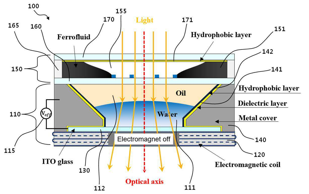
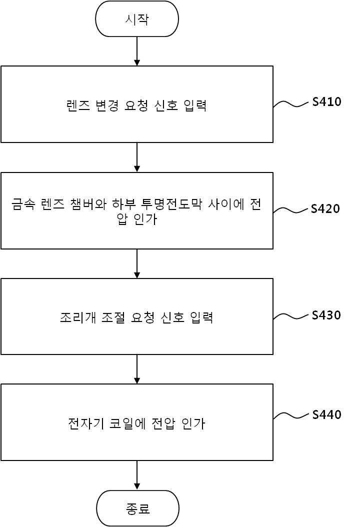
The present invention refers to a method for lubricating fluid optical device and method of driving the electromagnetic force electric with dampness method are disclosed. The electrowetting (Electrowetting) specially coated electrode electrically insulating solid surface to create a potential difference between the electrolyte electrolyte number by surface tension, contact angle can be varied artificially techniques are disclosed. This technique is mainly fluid lens (liquid lens) etc. development utilized electromagnetic paper (electronic display). On the other hand, the specific optical system for focusing a camera on to automatic focus (Auto Focus) RM function are disclosed. This capability greatly contrast (contrast) detecting an infrared sensor type and divided into, cookies etc. which contrasts with infrared license data received from the hybrid. On the other hand, device constructed to Image display device and an iris (Iris), opening amounts of the light traveling through the lens is adjusting device function are disclosed. The amount of light may be used to used to determine imaging plays an important role in regulating the sharpness of the week. Originally keyboard using the camera significantly increased fluid according based optical device developed for etc. against. Fluid-based optical device is typically, fluid lens (liquid lens) (liquid iris) diaphragm in fluid flow tides. However, the fluid based optical device is driving a drive for an separate is converted, size becomes difficult, etc. that door number DC power point. And, although the electrowetting method is advantageous in that a response speed, existing fluid based optical device includes fluid lens and fluid diaphragm is combined to individual element number is small, electrowetting techniques are applied to the entire board camera door number point that the pin is. The present invention refers to the electrowetting (Electrowetting) driven by the electromagnetic force (electromagnetic force) using fluid lens using optical device and method of driving the fluid driven by the fluid diaphragm with both a method for number are disclosed. According to one aspect of the present invention, electric with dampness a different optical device is disclosure fluid are disclosed. The optical device according to an embodiment of the present invention fluid, coupled to top of active video lens and said lens, said lens unit is, an electromagnetic coil, said electromagnetic coil and coupled to top, electric conductive lower transparent conduction layer, and said lower transparent conduction layer coupled to top, metal has the lens chamber and said liquid container receiving chamber of metal material contained in the liquid is made of, transparent electrically conductive liquid and act as a lens, said lens chamber from the inner periphery of the metal layer is formed are provided in multilayer insulating layer (Dielectric Layer) and minority number 1 (Hydrophobic Layer), said lower transparent conduction layer and said insulating layer is formed on said metal lens between the exterior, the diaphragm, liquid flows down channel and said channel is made on the edge of the, plays a role in light-absorbing with optical pick-up comprises a diaphragm. Said liquid receiving space is formed within the lower chamber in order to provide upper lens is formed on the first inclined surface and the inner periphery of said lens chamber surface, said area of said electrically conductive surface of the liquid to an under increased. Said lens chamber has a hollow cylindrical shape, said lens unit is, said remainder of said liquid receiving space of an electrically conductive fluid the space taken up by said lower transparent conduction layer and said space filled transparent insulating liquid and applying a voltage to the lens-voltage metal lens chamber having a predetermined wavelength. Said lower transparent conduction layer and said metal lens between the exterior voltage is applied to, an electrically conductive fluid on the surface of said curvature is generated. Said lower transparent conduction layer and said metal lens chamber is adjusted voltage applied between an electrically conductive fluid on the surface of said curvature is regul ated. Said lower transparent conduction layer and said voltage is applied to between the exterior metal lens, a convex lens or a concave lens in the form of an electrically conductive fluid said form change as follows. the diaphragm, said metal lens chamber joined to the top of the driving intermediate transparent conduction layer, said intermediate transparent conduction layer coupled to top of said spacer coupled to top of circular ring-shaped spacer and the driving of upper transparent conduction layer comprising a, said channel, said intermediate transparent conduction layer, said spacer and said upper transparent conduction layer a combination of transparent conduction layer and said intermediate space between said upper transparent conduction layer formed. the diaphragm, said upper transparent conduction layer laminated on an inside surface of the formed layer and applying a voltage to the electromagnetic coil voltage for squeezing said minority number 2 having a predetermined wavelength. Voltage is applied to said electromagnetic coil, said electromagnetic force of said electromagnetic coil by said magnetic fluid moves to toward the center of the channel. Said source of said electromagnetic coil is adjusted it is adjusted by the adjusting shifted toward the center of said channel at the center of, the top surface of the light array is regul ated the size of the openings. According to one aspect of the present invention other, electromagnetic coil, lower transparent conduction layer, liquid container receiving space by fluorination lens chamber, said liquid receiving space is made, including transparent electrically conductive liquid lens lens plays a role in, and liquid flows down channel, said channel is made on the edge of the, with optical pick-up including the diaphragm plays a role in light-absorbing device for driving the diaphragm part disclosure method including optical fluid are disclosed. The optical device according to an embodiment of the present invention method for driving fluid, receiving a lens change request signal, an input of said lower transparent conduction layer and said metal lens chamber along said lens change request signal applying voltage between, said video signal input to the input of the video request signal along said request signal and applying a voltage to the electromagnetic coil comprising the following steps. The optical device according to an embodiment of the present invention method for lubricating fluid electromagnetic force electric with dampness, driven by the electromagnetic force (electromagnetic force) using electrowetting (Electrowetting) driven by the fluid lens using fluid diaphragm by sending, and improve the performance of the variator lens mounted optical device, optical device can feed. Figure 1 shows a method for lubricating fluid optical device to determine the structure of electromagnetic force according to an embodiment of the present invention also electric with dampness unpredictable side. Figure 2 shows a fluid optical device of Figure 1 contains the hole are applied switching to exemplify the camera module. Figure 3 shows a fluid optical device according to an embodiment of the present invention also contains a surface curvature of lenses example. Figure 4 shows a device according to an embodiment of the present invention also contains to exemplify the optical fluid driving iris of a surface. Figure 5 shows a method for lubricating fluid optical device according to an embodiment of the present invention indicating flow method for driving electromagnetic force also electric with dampness. The backing used in representation of the specification it is apparent that in order to differently not providing language translators, comprising plurality of representation. In the specification, the term "consists of" or "includes" specification of articles various elements, or several steps which do not necessarily all including interpreted, some are not included and may be some components or, or additional components or step should be interpreted. In addition, a specification ".. Part "," module " means processing units and at least one function and the operation of term, implemented in software or hardware or a combination of hardware and software can be. Hereinafter, in the embodiment of the present invention are described with reference to the attached drawing various sequences. Figure 1 shows a method for lubricating fluid optical device to determine the structure of electromagnetic force according to an embodiment of the present invention also electric with dampness and the illustrated drawing, Figure 2 shows a fluid optical device of Figure 1 contains the applied switching to exemplify a camera module are disclosed. Hereinafter, electric optical device according to an embodiment of the present invention about 1 also with dampness a different fluid (100) is described structure of the, 2 also reference the on-sensors other. The reference also 1, according to an embodiment of the present invention fluid optical device (100) includes a lens section (110) and aperture portion (150) consists of including. For example, according to an embodiment of the present invention fluid optical device (100) is also 2 as shown, cylindrical lens section (110) on top, a disk shape in camera unit (150) can be combined with the, overall cylindrical shape can be formed. And, the fluid optical device (100) includes a variator lens module is applied as shown in fig. 2 for, housing (200) can be coupled to. More specifically described, as shown in fig. 1, fluid optical device (100) includes, an electromagnetic coil (120), lower transparent conduction layer (130), metal lens chamber (140), intermediate transparent conduction layer (160), spacer (spacer) (165) and upper transparent conduction layer (170) can be by a certain coupling. I.e., electromagnetic coil (120) upper, lower transparent conduction layer (130) is coupled. Wherein, electromagnetic coil (120) is, magnetic fluid (FerroFluid) (151) configuration for moving, fluid optical device (100) of a disk shape around an optical axis to prevent passage of the light transparent conduction layer (130) can be disposed along the rim of the rotor. I.e., electromagnetic coil (120) voltage is applied, an electromagnetic coil (120) generates the electromagnetic field, the magnetic fluid (151) can be reacted. An electromagnetic coil (120) in order to apply a voltage, fluid optical device (100) includes an electromagnetic coil (120) (not shown) can be comprising applying a voltage to the for squeezing the area. Lower transparent conduction layer (130) is electrically conductive ITO (Indium Tin Oxide) with implementation being glass. And, lower transparent conduction layer (130) on top of, metal material has hollow cylindrical metal lens chamber (140) is coupled. Wherein, metal lens chamber (140) at the bottom and at the top in order to provide hollow liquid accommodating space formed therein. Liquid receiving spaces are, an electrically conductive fluid (e.g., water) plays a role of a transparent lens (111) and an electrically conductive fluid (111) the remainder of the space taken up by a transparent insulating liquid (e.g., oil) space (112) can be filled. In addition, metal lens chamber (140) inner peripheral surface, as shown in fig. 1, lens chamber (130) from the inner periphery of the insulating layer (Dielectric Layer) (141) and minority layer (Hydrophobic Layer) (142) being extended in this order can be, insulating layer (141) is, lower transparent conduction layer (130) for isolation with metal lens chamber (140) and a lower transparent conduction layer (130) can be formed far. Metal lens chamber metal material (140) electrically conductive lower transparent conduction layer (130) between which a voltage can be applied, fluid optical device (100) the metal lens chamber (140) and a lower transparent conduction layer (130) for applying a voltage to the lens between voltage applying part (115) can be a. The configuration, according to an embodiment of the present invention fluid optical device (100) the lens portion (110) can be formed. And, lens section (110) of i.e., metal lens chamber (140) on top of, intermediate disc-shaped transparent conduction layer (160) formed on an active region, intermediate transparent conduction layer (160) on top, circular ring-shaped spacer (165) are coupled to, finally spacer (165) of a disk shape on top transparent conduction layer (170) is coupled. The, metal lens chamber (140) intermediate transparent conduction layer (160) is, metal lens chamber (140) intermediate an upper edge of transparent conduction layer (160) attached thereto by means of optical adhesive number can be sealingly engaging the rim of the rotor. Such intermediate transparent conduction layer (160), spacer (165) and upper transparent conduction layer (170) by passing through a combination of transparent conduction layer (160) and upper transparent conduction layer (180) can be liquid flows in a space between the thin channel (155) can be formed, channel (155) circular, the diaphragm having magnetic fluid (FerroFluid) plays a role in light-absorbing (151) can be filled. In addition, channel (155) of i.e., upper transparent conduction layer (170) inner sides, as shown in fig. 1, hydrophobic layer (Hydrophobic Layer) (193) stacked can be formed. The, magnetic fluid (151) is as aforementioned, electromagnetic coil applied voltage (120) an electromagnetic field generated by a channel (155) can be shifted toward the center in the rim of the rotor. The configuration, according to an embodiment of the present invention fluid optical device (100) in camera unit (150) can be formed. Hitherto, 2 also refers to the optical device according to an embodiment of the present invention fluid and also 1 (100) of established are described. 1 Also shown in fluid optical device (100) for the driving method, also after 3 and 4 describe also refers to less than 1000. Figure 3 shows a device according to an embodiment of the present invention also contains a surface curvature of lenses example optical fluid are disclosed. The reference also 3, contained in the liquid filled transparent lens plays a role of an electrically conductive fluid (111) is, as shown on the left side of Figure 3 initially, the surface of the liquid surface tension (i.e., insulating liquid (112) at a boundary) that are rounded form is under or over. I.e., an electrically conductive fluid (111) according to an embodiment of the present invention is fluid optical device (100) as a configuration corresponding lens, in the form of convex lens has a natural. In Figure 1 as aforementioned, liquid receiving space is metal lens chamber (140) of which inside is at the bottom to the top in order to provide a method for displaying, metal lens chamber (140) is equal to the inner periphery of the inclined surface. Through, an electrically conductive fluid (111) surface of the also 3 as shown, may have wider than the upper, metal lens chamber (140) according to the inclination angle of an inner circumferential surface of an electrically conductive fluid (111) surface area of s402. As well as, and in the embodiment of one short-sends, metal lens chamber (140) vertically formed inclined inner peripheral surface not disapproval. Then, metal lens chamber (140) and a lower transparent conduction layer (130) between the voltage is applied to, an electrically conductive fluid (111) surface of the curvature change occurs. I.e., as shown in the right of Figure 2, metal lens chamber (140) and a lower transparent conduction layer (130) in the form of convex lens type are a voltage between an electrically conductive fluid (111) on the principle or a concave lens can be changed by an electric form. As well as, and in the embodiment of one short-sends, e.g., metal lens chamber (140) and a lower transparent conduction layer (130) may be achieved with a voltage applied between the micro size, an electrically conductive fluid the (111) surface of the lower rail curvature of may be disclosed. Figure 4 shows a device according to an embodiment of the present invention also contains to exemplify the optical fluid driving iris of a surface are disclosed. The reference also 4, channel (155) on the edge of the diaphragm filled with magnetic fluid plays a role in light-absorbing (151) is, in Figure 1 the aforementioned electromagnetic coil (120) voltage is applied, an electromagnetic coil (120) electromagnetic fields generated, as shown in the right of Figure 4, channel (155) moves toward the center of the, a front light optical device (100) of the size of the openings can be gradually reduced. I.e., in Figure 1 as aforementioned, lens (110) a lower electromagnetic coil (120) is applied voltage, channel (155) on the edge of the filled with magnetic fluid (151) is electromagnetic coil (120) of channel 110b (155) can be moved a distance toward the center of the. Then, an electromagnetic coil (120) when the voltage applied to number, magnetic fluid (151) is in-situ channel (155) can be moved to the rim of the rotor. For example, an electromagnetic coil (120) particles to the magnitude of the voltage applied to controlled magnetic fluid (151) channel (155) may be achieved with a fine at the center shifted toward the center of, the front light optical device (100) can be sized opening. Figure 5 shows a method for lubricating fluid optical device according to an embodiment of the present invention indicating the flow of electromagnetic force also electric with dampness method are disclosed. In Figure 5 fluid optical device (100) is, shutter, photographing mode setting button in the functional configuration of user input means such as general camera unit can be, in hereinafter, fluid optical device (100) of Figure 5 to explain flow mainly consisting of less than 1000. S510 step, fluid optical device (100) via a change request signal to an user input means from a testee. S520 in, fluid optical device (100) according to input signal group is change request metal lens chamber (140) and a lower transparent conduction layer (130) applies a voltage between. The, metal lens chamber (140) and a lower transparent conduction layer (130) type are lens plays a role in voltage between the electrically conductive liquid (111) surface of the curvature change occurs. For example, metal lens chamber (140) and a lower transparent conduction layer (130) may be achieved with a voltage applied between the micro size, the an electrically conductive fluid (111) can be curvature of the surface of the lower rail. S530 in, fluid optical device (100) includes a user unit for video request signal from a testee. S540 in, fluid optical device (100) according to the input of the request signal is video lens (110) a lower electromagnetic coil (120) applies a voltage to the. For example, a diaphragm size video request signal selection by a user can be spirally size information. The, for squeezing an electromagnetic coil (120) plays a role in a magnetic voltage type are diaphragm (151) channel (155) move within the substrate. For example, lens (110) a lower electromagnetic coil (120) is applied voltage, channel (155) on the edge of the filled with magnetic fluid (151) is electromagnetic coil (120) of channel 110b (155) can be moved a distance toward the center of the. For the purposes of disclosure of the present invention in the embodiment is a and in the example, the present invention if one skilled in the range of the present invention idea and having common knowledge of various modification, change, magnetic by percussion, the modified, will change and addition of the following claim must to belong. 100: Fluid optical device 110: Lens 120: Electromagnetic coil 130: Lower transparent conduction layer 140: Metal lens chamber 150: Diaphragm unit 160: Intermediate transparent conduction layer 165: Spacer (spacer) 170: Upper transparent conduction layer Disclosed are a liquid optical apparatus using electrowetting and an electromagnetic force and an actuating method thereof. The liquid optical apparatus includes a lens unit and an iris unit coupled to an upper portion of the lens unit. The lens unit includes: an electromagnetic coil; a lower transparent conductive film which is coupled to an upper portion of the electromagnetic coil, and has electric conductivity; a metal lens chamber which is coupled to an upper portion of the lower transparent conductive film, and has a metal material having a liquid accommodation space formed therein; and a transparent electric-conductive liquid which is filled in the liquid accommodation space and serves as a lens. A dielectric layer and a first hydrophobic layer are formed to be sequentially layered from the inner circumferential surface of the metal lens chamber. A dielectric layer is formed between the lower transparent conductive film and the meal lens chamber. The iris unit includes a channel in which a liquid flows, and a magnetic fluid which is filled in an edge of the channel and serves as an iris. Method for lubricating fluid optical device in electromagnetic force electric with dampness, lens section; a diaphragm coupled to top of active and said lens, said lens unit is, electromagnetic coil; said electromagnetic coil and coupled to top, electric conductive lower transparent conduction layer; and said lower transparent conduction layer coupled to top, liquid container receiving chamber of metal material which has lens chamber; said liquid receiving space is made, the transparent lens plays a role of an electrically conductive fluid; said liquid receiving space the space taken up by the remainder of the space filled with an electrically conductive fluid said transparent insulating liquid; and said lower transparent conduction layer and said metal lens chamber and applying a voltage to the lens-voltage supply part, said metal lens chamber from an inner peripheral surface formed are provided in multilayer insulating layer (Dielectric Layer) and number 1 (Hydrophobic Layer) hydrophobic layer, said lower transparent conduction layer and said insulating layer is formed on said metal lens between the exterior, said diaphragm unit, said metal lens chamber joined to the top of the driving intermediate transparent conduction layer; said intermediate transparent conduction layer coupled to top of circular ring-shaped spacer; said spacer coupled to top of the driving upper transparent conduction layer; said intermediate transparent conduction layer, said spacer and said upper transparent conduction layer a combination of transparent conduction layer and said upper transparent conduction layer in a predetermined space between and intermediate said, liquid flows down channel; said channel is made of the rim of the rotor, the diaphragm plays a role in light-absorbing with magnetic fluid; said upper transparent conduction layer laminated on an inside surface of the hydrophobic layer formed number 2; applying a voltage to the electromagnetic coil and said fluid optical device including voltage supply part for squeezing characterized. According to Claim 1, said liquid receiving space is formed within the lower chamber in said upper metal lens is formed on the inner peripheral surface and an inclined surface in order to provide said metal lens chamber, to an under surface of said light from said optical device characterized in that an electrically conductive fluid fluid. According to Claim 1, characterized in that said metal lens chamber is hollow dome-shaped fluid optical device. According to Claim 1, said lower transparent conduction layer and said metal between voltage is applied to the lens chamber, characterized in that said curvature on the surface of an electrically conductive fluid as the fluid optical device. According to Claim 1, said lower transparent conduction layer and said metal lens chamber is adjusted voltage applied between an electrically conductive fluid on the surface of said fluid optical device with adjustable curvature characterized. According to Claim 1, said lower transparent conduction layer and said metal lens between the exterior voltage is applied to the, said convex lens or a concave lens in the form of an electrically conductive fluid is characterized optical device changes in fluid form. Back number Back number According to Claim 1, voltage is applied to said electromagnetic coil, said electromagnetic force of said electromagnetic coil by said channel it is characterized optical device toward the center of the movement of the fluid. According to Claim 1, said source of said electromagnetic coil is adjusted it is adjusted by the adjusting shifted toward the center of said channel at the center of, the top surface of the optical device is the size of the openings to control fluid characterized by light. Back number