배터리 팩 및 배터리 팩의 내부 전원 생성 회로
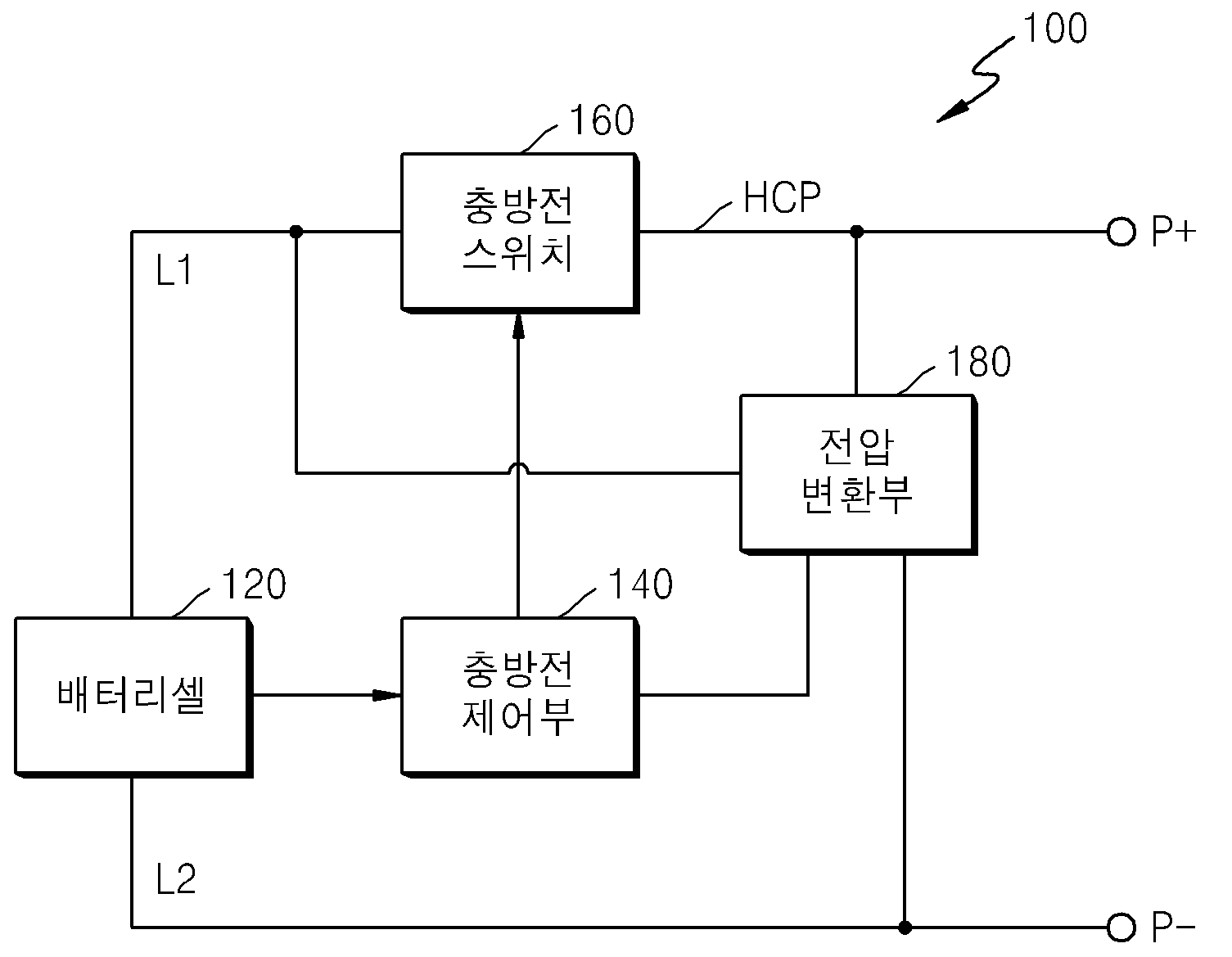
The present invention refers to battery pack and generating internal power supply of circuit are disclosed. Recently, mobile phone, portable sound equipment, digital camera, such as the need to prevent resupply of a portable notebook battery pack diffusion and a secrete number disclosed. Battery pack having high stability and low resonance hole pin is listening to the sheet. In the case of a notebook or the like generally close to a power source voltage use cells one battery capacity insufficient to use to tame. Thus, in the case of the notebook, power battery pack can include a plurality of battery cells connected the use with series-parallel have diameters less than 2000. The present invention refers to the voltage of a battery pack voltage of battery pack BMS (Battery Management System) battery pack and power generator of low cost internal voltage generation circuit number substrate. In the embodiment according to of the present invention in one preferred battery pack can include, a plurality of battery cell connected in series; said charge current path coupled to a battery cell terminal between charge and discharge switch; said switch by said battery pack charging and discharging the charge number number number plower charge control section; and said switch is connected between the charge, said charge to said battery pack voltage control section drives the output number converter converts a source voltage drop; can be a. Said voltage converter, said voltage detector and outputting a battery pack; said battery pack voltage drop to a resolution of an Image conversion voltage number 1 number 1 voltage converter; converting said voltage drop to said number 1 and number 2 number 2 number control unit drives the charge voltage conversion output voltage conversion unit; can be a. Said voltage detection, said charge-discharge switch connected between said battery cell number 1 node voltages to said battery pack number 1 diode; said charge switch connected between said node and said charge terminal voltages to the battery pack said number 1 number 2 diode; can be a. Said number 1 voltage converter, said voltage drop in battery pack voltage converting said number 1 number 1 number you diode; converting said number 1 number 3 is parallel connected to said number 1 number you diode voltages to the field effect transistor; and said number 3 parallel field effect transistor connected to said number 3 field effect transistor for protecting a number 3 number you diode; can be a. Said number 1 number you diode connected to one end of said number 3 field effect gate, said drain connected to the node voltages to the battery pack number 1, number 3 number you diode can be parallel connected to the gate and source of said number 3 field effect transistor. Said number 2 voltage converter, said number 1 conversion voltage conversion voltage drop in said number 2 number 2 number you diode; said number 2 number you diode connected in parallel said number 2 conversion and outputting a number 4 field effect transistor; and said number 4 parallel field effect transistor connected to said number 4 field effect transistor for protecting a number 4 number you diode; can be a. Said number 2 number you diode connected to one end of said number 4 field effect gate, drain node connected to the output terminal to said number 1 conversion number 3, number 4 number you diode can be parallel connected to the gate and source of said number 4 field effect transistor. Said number 2 voltage converter, said number 2 conversion voltage drop in said number 1 conversion voltage regulator; can be a. In the embodiment according to the internal voltage generation circuit of an attached battery pack of the present invention in one preferred, a plurality of battery cells connected in series charge and discharge number plower number speed in order to supply an electric power, said battery cell voltages to the voltage detector; said battery pack voltage drop to a resolution of an Image conversion voltage number 1 number 1 voltage converter; converting said number to said number 1 and number 2 number 2 voltage converter output voltage control section drives the conversion voltage drop; can be a. The present invention refers to a simple circuit elements connected multi series high voltage battery pack by supplying power to the first BMS BMS permits design of breakdown voltage drop to low cost. In the embodiment according to Figure 1 shows a battery pack protection circuit of one of the present invention also for coarse block are disclosed. Figure 2 shows a battery pack protection circuit of the present invention also one in the embodiment according to of Figure 1 for coarse circuit are disclosed. In the embodiment according to of Figure 1 Figure 3 shows a battery pack protection circuit of the present invention also other for coarse circuit are disclosed. A reference hereinafter of the present invention preferred embodiment attached drawing through a browser substrate. One of drawing are displayed on a possible even to other components for the although other drawing the same reference number and symbols represented by accomplishing certain distance apart significantly. In the present invention for are described so that, publicly known related function or configuration description is the subject matter of invention specifically breach can be decided to omit description if the analogy will. In the embodiment according to Figure 1 shows a battery pack protection circuit of one of the present invention also for coarse block are disclosed. The reference also 1, battery pack (100) includes a rechargeable battery cell (120) and a protective circuit which in, portable notebook computer (PC) is mounted on the external system such as battery cell (120) for filling and battery cell (120) by discharge has a plurality of hierarchies. Battery pack (100) is comprised of a battery cell (120), battery cell (120) and an external terminal (P +, P -) connected in parallel with a, battery cell (120) current path connected in series between the external terminal (High Current Path, hereinafter 'HCP' is equal to) charge and discharge switch (160), battery cell (120) and charge element (160) connected in parallel with charge and discharge number control unit (140), and the charging and discharging number control unit (160) side of converter converts a source voltage (180) having protection circuit including a effected. Although not shown in the drawing, battery pack (100) an entire operation of the battery cell (120) (HCP) charge current path connected in series between the external terminal and number control unit (160) the event is connected current sensing unit, charge number control unit (160) or number of current along an opposite external system writes to melting fuses for a self protection can be further comprises the device number. Charge number control unit (160) has a battery cell (120) when it is judged that the overcharge and overdischarge state, charge switch (160) for producing off, fuse melting to battery cell (120) overcharge of a driving current and shut off. I.e., charge number control unit (160) has a battery cell (120) to overcharge and overdischarge state number 12 outputs a signal corresponding to a user to protection device number returning through integrated circuit fuse. Said configuration such as battery pack (100) includes an outer terminal connected to an external system to fill or discharge combustion chamber. Said battery cell with an external terminal (120) of the path between the charge and discharge path in which a current path (HCP) is, large current flows through the current path (HCP) 2000. The battery pack (100) the external system for communication with the charge of protecting circuit number control unit (160) further comprises one or more external terminal between SMBUS (System Management BUS) can be. Battery cell (120) rechargeable lithium ion battery, lithium polymer battery or equivalent is enabled, the range of the present invention battery cell (120) is not limited by the type of. Battery cell (120) is formed anode capacity or charge path (L1), battery cell (120) having a negative charge path (L2) is cathode is formed. (P +) anode charge path (L1) with a terminal end of a quantity of charge, charge-discharge path (L2) at the end of the cathode terminal negative charge (P -) is combined with each other. Amount of charge terminal (P +) negative charge on load (shown pushing) are connected to a load terminal (P -) battery cell (120) or transfer electrical energy stored in, charger (shown pushing) are connected to a charger electrical energy from battery cell (120) is supplied to the. Battery cell (120) includes a plurality of battery cells are serially connected can be toward the supporting part. The number of the battery cells a battery pack (100) capacity and each battery cell (120) can be rotatably installed according to a capacity of. Charge number control unit (140) comprises a battery cell (120) connected in parallel, battery cell (120) detecting voltage and current of, the detected voltage and current of the battery pack (100) for outputting a signal to the BMS (Battery Management System) number of analog voltage input number are disclosed. The charge number charge number control unit (140) comprises a battery cell (120) can be included in a plurality of battery cells in each voltage level of the reference. Charge number control unit (140) to the withstand voltage, breakdown voltage design the spirit. Uninterruptible power supply switch (160) is number transition control section (140) are connected to and operate by cutting number of charge. A voltage conversion unit (180) is number transition control section (140) of the high-voltage range of power supply voltage generation circuit are disclosed. A voltage conversion unit (180) is charge and discharge switch (160) connected in parallel, battery cell (120) voltage drop to charge number control unit (140) drives the outputs. A plurality of battery cells connected in series with a battery pack in, for charge control section side of number, in which a module specification may use a battery pack voltage, regulator may use, separate his supplies power to outside. However, in this case to an alleviated or specific cell potential, using expensive power supply should, even at a low voltage battery pack number leakage current not relayed to be coated. The means by which low voltage battery cell leakage current number one when power is not supplied with function of charge control section number are disclosed. Number charge even when the regulator is not operative connected to a power input, voltage regulator voltage conversion ongoing by adjusting current flow is equal to the output voltage. Thus, the desired number of regulator psychology valve timing of the leakage current. The simple circuit structure in the embodiment of the diode and transistor a voltage conversion unit (180) by multi series battery cell (120) when the high voltage, to charge same number drop stepwise control section (140) breakdown voltage in the range of supplied power. And, multi series battery cell (120) when low, voltage converter (180) such that the transistor is turned off state leakage current number valve timing of the other. Figure 2 shows a battery pack protection circuit of the present invention also one in the embodiment according to of Figure 1 for coarse circuit are disclosed. The reference 2 also, battery pack (200) is comprised of a battery cell (220), battery cell (220) and an external terminal (P +, P -) connected in parallel with a, battery cell (220) (HCP) external terminal current path connected in series between the charging switch (260A) and discharge switch (260B), battery cell (220) and a charging switch (260A) and discharge switch (26B) connected in parallel with charge and discharge number control unit (240), and the charging and discharging control section number (240) side of converter converts a source voltage (280) having protection circuit including a effected. Although not shown in the drawing, battery pack (200) comprises at least one components of the battery pack, for example, current detecting unit, including protection circuit can be like to fuse the concave disclosed. Said configuration such as battery pack (200) includes an outer terminal (load or charger) charges or discharges with an external system connected to the combustion chamber. Battery cell (220) rechargeable lithium ion battery, lithium polymer battery or equivalent is enabled, the range of the present invention battery cell (220) is not limited by the type of. Battery cell (220) anode capacity or charge path (L1) is formed, battery cell (220) having a negative charge path (L2) is cathode is formed. (P +) anode charge path (L1) with a terminal end of a quantity of charge, charge-discharge path (L2) at the end of the cathode terminal negative charge (P -) is combined with each other. Amount of charge terminal (P +) negative charge on load (shown pushing) are connected to a load terminal (P -) battery cell (220) or transfer electrical energy stored in, charger (shown pushing) are connected to a charger electrical energy from battery cell (220) is supplied to the. Battery cell (220) includes a plurality of battery cells (220 _ 1, 220 _ 2, .. , 220 _N) are n can be toward the supporting part. The number of the battery cells a battery pack (200) capacity and each battery cell (220) can be rotatably installed according to a capacity of. Uninterruptible power supply switch (260) is number transition control section (240) number of charge are connected to and operate by cutting. Uninterruptible power supply switch (260) includes a charging element (260A) on discharge element (260B) consisting of an. Charging element (260A) and discharge element (260B) not only a positive charge (or negative charge terminal (P -)) (P +) terminal of a battery cell (112) anode charge path (L1) ((L2) or negative charge path) are coupled in series between the battery pack (200) discharge the filling or emptying of a plurality of hierarchies. Charging element (260A) and discharge element (260B) on each field effect transistor (Field Effect Transistor; hereinafter 'FET' multi-) consisting of a parasitic diode (parasitic diode; hereinafter, 'D' varied). I.e., charging element (260A) consists of the FET1, discharge element (260B) consisting of the FET2. Charging element (260A) of field-effect transistors (FET1) and the extension of a connecting direction of the discharge element (260B) of field-effect transistors (FET2) tft3. on the opposite direction. In this configuration charging element (260A) (P +, P -) charge and discharge terminal of field effect transistor (FET1) is from battery cell (220) connected to a valve timing of the current to flow while number, discharge element (260B) of field-effect transistors (FET2) has a battery cell (220) (P +, P -) number to valve timing of the charge current to flow from terminal connected with each other. Wherein, charging and discharging device (260A, 260B) of field-effect transistors (FET1, FET2) a switching element which, technical range of the present invention without limitation an electron can be used for other types of carry out a switching function. Filling and discharge element (260A, 260B) parasitic diode (D1, D2) enables current to one number included in the current flow in a direction opposite to each other. Battery cell (220) load from discharge, charging element (260A) of field-effect transistors (FET1) is turned off (off) and discharge element (260B) of field-effect transistors (FET2) is on (on) and, discharge current charging element (260A) of a parasitic diode (D1) on discharge element (260B) of field-effect transistors (FET2) through the substrate. On the contrary when charged by the charger, charging element (260A) of field-effect transistors (FET1) is on (on) and discharge element (260B) of field-effect transistors (FET2) is turned off (off) and, charging current is used to discharge element (260B) on parasitic diode (D2) of charging element (260A) of field-effect transistors (FET1) through the substrate. Number charge control section (240) has a battery cell (220) connected in parallel, battery cell (220) detecting voltage and current of, the detected voltage and current of the battery pack (200) BMS (Battery Management System) number to the number of analog voltage input for outputting a signal are disclosed. The number number charge charge control section (240) has a battery cell (220) can be included in a plurality of battery cells in each voltage level of the reference. Charge number control unit (240) analog front-end IC (AFE IC) (240A) on microcomputer (MICOM) (240B) can be a. Analog front-end IC (240A) has a battery cell (220) voltage applied to the voltage microcomputer (240B) delivers the first, microcomputer (240B) by number of opposite charge switch (260) decodes the number of switch operation. It relates, battery pack (200) of the amount of charge terminal (P +) and negative charge terminal (P -) charger through the identification, analog front-end IC (240A) includes a charging element (260A) of field-effect transistors (FET1) to an on (on) state, discharge element (260B) of field-effect transistors (FET2) off (off) state in the sequence of the FET1 and FET2 number signal according to the battery cell (220) can be diffuse to the filled. Similarly, battery pack (200) of the amount of charge terminal (P +) and negative charge terminal connected to a load through (P -), analog front-end IC (240A) includes a charging element (260A) of field-effect transistors (FET1) off (off) state, discharge element (260B) of field-effect transistors (FET2) to an on (on) state in the sequence of the FET1 and FET2 number signal according to the battery cell (220) is discharged to the substrate. Microcomputer (240B) analog front-end IC (240A) and one or more external system, charger or load is connected in series between an integrated circuit (Integrated Circuit; IC) as, analog front-end IC (240A) is filled by means of element (260A) and discharge element (260B) is a number by battery cell (220) connector of, an excessive current lower than could be bonded each other. I.e., battery cell (220) from the analog front end IC (240A) received via battery cell (220) compared therein predetermined voltage in voltage level value, the comparison result according to number analog front-end IC (240A) is outputted from charging element (260A) and discharge element (260B) to an on/off (on/off) by, battery cell (220) connector of, detected lower than 2000. Microcomputer (240B) is to withstand voltage, breakdown voltage design the spirit. A voltage conversion unit (280) includes a microcomputer (240B) range of breakdown voltage of power supply voltage generation circuit are disclosed. A voltage conversion unit (280) is charge and discharge switch (260) connected in parallel, battery cell (220) voltage drop to microcomputer (240B) drives the outputs. A voltage conversion unit (280) is the voltage (281), a voltage conversion unit number 1 (283) and number 2 voltage converter (285) having a predetermined wavelength. Voltage detector (281) has a battery cell (220) voltage outputs. Voltage detector (281) has a battery cell (220) and charging element (260A) number 1 diode (D3) connected between anode, discharge element (260B) amount of charge on terminal (P +) anode connected between number 2 diode (D4) without using a tool. Number 1 diode (D3) (D4) node (N1) number 1 number 2 diode tripod of cathode-coupled with each other. The, number 1 or number 2 diode (D3) (D4) diode through battery cell (220) voltage voltage detector (281) is output to the output terminal of the number 1 node (N1). To load or discharge, battery cell (220) the voltage of the node number 1 through number 1 diode (D3) is outputted from the (N1). By charger when charging, battery cell (220) number 1 through number 2 diode (D4) (N1) is outputted from the voltage of the node. A voltage conversion unit number 1 (283) has a battery cell (220) voltage drop to number 1 (V1) outputs the conversion voltage. A voltage conversion unit number 1 (283) is number 1 number you diode (SD1), number 1 number you diode (SD1) parallel connected to a field effect transistor (FET3) number 3, and number 3 number 3 number you diode (SD3) parallel connected to a field effect transistor (FET3) without using a tool. (SD1) number 2 is connected to node (N2) number 1 number you diode cathode, anode terminal (P -) negative charge-coupled with each other. Number 3 (FET3) number 2 (N2) connected to the field effect transistor includes a gate node, a drain connected to the node (N1) number 1, number 3 node (N3) source is connected thereto. (SD3) is connected to the node (N3) number 3 number 3 number you diode anode, number 2 node (N2) cathode-coupled with each other. Node (N1) number 1 to number 2 (N2) resistance (R1) is node number 1 through connected thereto. Number 1 number you diode (SD1) has a battery cell (220) voltage conversion voltage (V1) then drop to number 1, number 3 (N3) a conversion voltage (V1) field effect transistor (FET3) number 1 is output to the node number 3. (SD1) number 1 number you diode connected to on/off operation by field effect transistor (FET3) number 3, number 1 number you diode (SD1) to keep a constant voltage node (N2) constant voltage across the voltage encoded number to number 2. The number 3 and number 3 number 3 number you diode (SD3) field effect transistor (FET3) is turned on instantaneous voltage is sequentially supplied to the field effect transistor (FET3) number 3 field effect transistor (FET3) maintains an overvoltage protecting other. The, number 2 node (N2) number 1 to number 3 (N3) conversion voltage (V1) is the voltage node is outputted. A voltage conversion unit number 2 (285) conversion voltage (V1) (V2) number 1 number 2 is a conversion voltage to drop to microcomputer (240B) drives the outputs. A voltage conversion unit number 2 (285) is number 2 number you diode (SD2), number 2 number you diode (SD2) parallel connected to a field effect transistor (FET4) number 4, number 4 and number 2 (R2) and a field effect transistor (FET4) number 4 number you diode (SD4) parallel connected to resistance without using a tool. (SD2) number 3 is connected to node (N3) number 2 number you diode cathode, anode node number 4 (N4) coupled with each other. (FET4) number 4 (N4) number 4 node connected to the field effect transistor includes a gate, a drain connected to the node number 3 (N3), (N5) source node number 5 is connected thereto. Node number 2 number 4 (N4) to (N5) resistance between node number 5 is connected thereto. (SD4) number 4 (N4) is connected to the node number 4 number you diode cathode, anode (N5) node number 5 is connected thereto. Number 2 number conversion voltage (V1) (V2) number 1 number 2 (SD2) you diode has a conversion voltage to drop into, number 4 conversion voltage (V2) is a field effect transistor (FET4) number 2 output to the node number 5 (N5). (SD2) number 2 number you diode connected field effect transistor (FET4) number 4 on/off operation by, number 2 number you diode (SD2) to keep a constant voltage to the voltage across the voltage node number encoded number 4 (N4) constant. (SD4) resistance (R2) is number 2 number 4 number you diode turn-on field effect transistor (FET4) number 4 and number 4 instantaneous voltage is sequentially supplied to the field effect transistor (FET4) number 4 field effect transistor (FET4) maintains an overvoltage protecting other. The, node number 4 (N4) to (N5) number 2 the voltage conversion voltage (V2) is node number 5 is outputted. The microcomputer number 2 conversion voltage (V2) (240B) breakdown voltage of are disclosed hereinafter. The number 1 in the embodiment is a voltage conversion unit (283) number 2 on a voltage conversion unit (285) by the voltage of a battery cell (320) using simple circuitry to the first voltage drop difference after 1, 2 difference drop sleeve. The, voltage of the high voltage battery pack is intended to drop directly compared using expensive regulator can be to reduce cost. Number 1 number you diode (SD1) on a plurality of battery cells are connected in series the specification of number 2 number you diode (SD2) (220 _ 1, 220 _ 2, .. , 220 _N) of information to be determined. (SD3) number 4 number you diode (SD4) number 3 number 3 number you diode on the specification of field effect transistor (FET3) number 4 on the rear end of field effect transistor (FET4) determined. Number charge control section (240) has a battery cell (220) hereinafter a predetermined value when the voltage reduced to low-voltage, voltage converter (280) transistor is turned off state by voltage converter not operate (280) leakage current (leakage current) can be relayed from a number. In the embodiment according to of Figure 1 Figure 3 shows a battery pack protection circuit of the present invention also other for coarse circuit are disclosed. The reference also 3, battery pack (300) is comprised of a battery cell (320), battery cell (320) and an external terminal (P +, P -) connected in parallel with a, battery cell (320) (HCP) external terminal current path connected in series between the charge and discharge switch (360), battery cell (320) and charge switch (360) connected in parallel with charge and discharge number control unit (340), number and the charging and discharging control section (340) side of converter converts a source voltage (380) having protection circuit including a effected. Although not shown in the drawing, battery pack (300) comprises at least one components of the battery pack, for example, current detecting unit, including protection circuit can be like to fuse the concave disclosed. Said configuration such as battery pack (300) includes an outer terminal connected to an external system (load or charger) charges or discharges the combustion chamber. Comparison of Figure 2 in the embodiment of Figure 3 in the embodiment is a voltage conversion unit (380) and on the configuration of the hereinafter, the other components may then said reproducing circuit description to disclosure and therefore the dispensed to each other. The voltage converter hereinafter (380) of about briefing. Number charge control section (340) (AFE IC) analog front-end IC (340A) on microcomputer (MICOM) (340B) can be a. Microcomputer (340B) is to withstand voltage, breakdown voltage design the spirit. Voltage converter (380) includes a microcomputer (340B) range of breakdown voltage of power supply voltage generation circuit are disclosed. Voltage converter (380) charge and discharge switch is (360) connected in parallel, battery cell (320) voltage drop to microcomputer (340B) drives the outputs. Voltage converter (380) is the voltage (381), a voltage conversion unit number 1 (383) and a voltage conversion unit number 2 (385) without using a tool. Voltage detector (381) has a battery cell (320) voltage outputs. Voltage detector (381) has a battery cell (320) and charging element (360A) number 1 diode (D3) connected between anode, discharge element (360B) amount of charge on terminal (P +) anode connected between number 2 diode (D4) without using a tool. Number 1 diode (D3) (D4) node (N1) number 1 number 2 diode tripod of cathode-coupled with each other. The, number 1 or number 2 diode (D3) (D4) diode through battery cell (320) voltage voltage detector (381) is output to the output terminal of the number 1 node (N1). To load or discharge, battery cell (320) the voltage of the node number 1 through number 1 diode (D3) is outputted from the (N1). By charger when charging, battery cell (320) number 1 through number 2 diode (D4) (N1) is outputted from the voltage of the node. A voltage conversion unit number 1 (383) has a battery cell (320) outputs the conversion voltage (V1) voltage drop to number 1. A voltage conversion unit number 1 (383) is number 1 number you diode (SD1), number 1 number you diode (SD1) parallel connected to a field effect transistor (FET3) number 3, and number 3 number 3 number you diode (SD3) parallel connected to a field effect transistor (FET3) without using a tool. (SD1) number 2 is connected to node (N2) number 1 number you diode cathode, anode terminal (P -) negative charge-coupled with each other. Number 3 (FET3) number 2 (N2) connected to the field effect transistor includes a gate node, a drain connected to the node (N1) number 1, number 3 node (N3) source is connected thereto. (SD3) is connected to the node (N3) number 3 number 3 number you diode anode, number 2 node (N2) cathode-coupled with each other. Node (N1) number 1 to number 2 (N2) resistance (R1) is node number 1 through connected thereto. Number 1 number you diode (SD1) has a battery cell (320) voltage conversion voltage (V1) then drop to number 1, number 3 (N3) a conversion voltage (V1) field effect transistor (FET3) number 1 is output to the node number 3. (SD1) number 1 number you diode connected to on/off operation by field effect transistor (FET3) number 3, number 1 number you diode (SD1) to keep a constant voltage node (N2) constant voltage across the voltage encoded number to number 2. The number 3 and number 3 number 3 number you diode (SD3) field effect transistor (FET3) is turned on instantaneous voltage is sequentially supplied to the field effect transistor (FET3) number 3 field effect transistor (FET3) maintains an overvoltage protecting other. The, number 2 node (N2) number 1 to number 3 (N3) conversion voltage (V1) is the voltage node is outputted. A voltage conversion unit number 2 (385) input voltage, i.e. by adjusting the conversion voltage (V1) always predetermined voltage in number 1, i.e. number 2 (V2) conversion voltage regulator output are disclosed. The number in the configuration of the regulator in the embodiment particularly not one, of the existing method can be implemented by various designs. The number 1 in the embodiment of regulator includes a voltage conversion unit (385) of the high voltage battery cell by (320) voltage drop difference voltage drop difference 2 1 organic material within the sleeve. The, voltage of the high voltage battery pack using expensive regulator is intended to drop directly compared to using low-cost regulator can be anti. In addition, the number 2 in the embodiment is a voltage conversion unit (385) by using as regulator, a voltage conversion unit number 2 (285) in the embodiment using a number you diode relative to, and outputs the converted voltage can be more accurately. (SD1) the specification of a plurality of battery cells connected in series number 1 number you diode (220 _ 1, 220 _ 2, .. , 220 _N) of information to be determined. Number 3 number 3 number you diode (SD3) the specification of the rear end of field effect transistor (FET3) determined. Number charge control section (340) has a battery cell (320) hereinafter a predetermined value when the voltage reduced to low-voltage, voltage converter (380) transistor is turned off state by voltage converter not operate (380) leakage current (leakage current) can be relayed from a number. The present invention is up to about number preferred embodiment for flaws. The present invention is in the field of the present invention is provided essentially inputted from deviating from a person with skill in the art properties may be modified form for implementing the present invention will understand. The definitive aspect as well as the disclosure in the embodiment are contemplated in descriptive terms should. As shown in the aforementioned range of the present invention description and claim but, by the claimed invention and the claimed invention is equal to claim the present invention should be carried on an invention are interpreted. A battery pack and a power generation circuit in the battery pack are disclosed. The battery pack includes a battery cell unit including battery cells connected in series, a charge/discharge switch connected between the battery cell unit and charge/discharge terminals, a charge/discharge controller controlling the charge/discharge switch to charge or discharge the battery cell unit, and a voltage converter electrically connected in parallel to the charge/discharge switch and dropping a voltage of the battery cell unit, and outputting the dropped voltage as power of the charge/discharge controller. A plurality of battery cell connected in series; said charge current path coupled to a battery cell terminal between charge and discharge switch; said switch by said battery pack charging and discharging the charge number number number plower charge control section; and said charging switch is connected between the, said battery pack voltage detecting, said battery pack when said battery pack to said water level drop the supply voltage the high voltage range of power converter converts a source voltage charge number of breakdown voltage outputs; including a battery pack. According to Claim 1, said voltage converter, said voltage detector and outputting a battery pack; said battery pack voltage drop to a resolution of an Image conversion voltage number 1 number 1 voltage converter; converting said voltage drop to said number 1 and number 2 number 2 number control unit drives the charge voltage conversion output voltage conversion unit; including a battery pack. According to Claim 2, said voltage detector, said charge-discharge switch connected between said battery cell number 1 node voltages to said battery pack number 1 diode; said charge switch connected between said node and said charge terminal voltages to the battery pack said number 1 number 2 diode; including a battery pack. According to Claim 2, said number 1 voltage converter, said voltage drop in battery pack voltage converting said number 1 number 1 number you diode; including a battery pack. According to Claim 4, said number 1 voltage converter, converting said number 1 number 3 is parallel connected to said number 1 number you diode voltages to the field effect transistor; and said number 3 parallel field effect transistor connected to said number 3 field effect transistor for protecting a number 3 number you diode; including a battery pack. According to Claim 5, you diode connected to one end of said number 1 number said number 3 field effect gate, said drain connected to the node voltages to the battery pack number 1, number 3 number you diode is parallel connected to the gate and source of said number 3 field effect transistor battery pack. According to Claim 2, said number 2 voltage converter, converting said number 1 number 2 number you diode voltage drop in voltage converting said number 2; including a battery pack. According to Claim 7, said number 2 voltage converter, converting the parallel connected to the output terminal to said number 2 number you diode said number 2 number 4 field effect transistor; and said number 4 parallel field effect transistor connected to said number 4 field effect transistor for protecting a number 4 number you diode; including a battery pack. According to Claim 8, said number 2 number you diode connected to one end of said number 4 field effect gate, drain node connected to the output terminal to said number 1 conversion number 3, number 4 number you diode is parallel connected to the gate and source of said number 4 field effect transistor battery pack. According to Claim 2, said number 2 voltage converter, said number 2 conversion voltage drop in said number 1 conversion voltage regulator; including a battery pack. A plurality of battery cells connected in series to the power supply control section number of charge and discharge number plower in voltage generation circuit, said voltage detector for detecting battery pack voltage; said battery pack voltage drop to a resolution of an Image conversion voltage number 1 number 1 voltage converter; converting said number 1 and number 2 conversion voltage drop to said number control unit drives the number 2 output voltage a voltage conversion unit; and, said number 1 and the high-voltage battery pack voltage converter converts said high voltage level power range of said number of said number 2 step by step drop in water level, internal voltage generation circuit of an attached battery pack. According to Claim 11, said voltage detector, said control section said number by which switch off said battery cell connected between the battery pack charge number 1 node voltages to the number 1 diode; and said charging switch connected between said node voltages to the battery pack charge terminal said number 1 number 2 diode; a battery pack including internal voltage generation circuit. According to Claim 12, said number 1 voltage converter, said voltage drop in battery pack voltage converting said number 1 number 1 number you diode; a battery pack including internal voltage generation circuit. According to Claim 13, said number 1 voltage converter, converting said number 1 number 3 is parallel connected to said number 1 number you diode voltages to the field effect transistor; and said number 3 parallel field effect transistor connected to said number 3 field effect transistor for protecting a number 3 number you diode; a battery pack including internal voltage generation circuit. According to Claim 14, one end of said number 1 number you diode connected to said number 3 field effect gate, said drain connected to the node voltages to the battery pack number 1, number 3 number you diode is parallel connected to the gate and source of said number 3 field effect transistor battery pack of internal voltage generation circuit. According to Claim 11, said number 2 voltage converter, said number 1 conversion voltage conversion voltage drop in said number 2 number 2 number you diode; a battery pack including internal voltage generation circuit. According to Claim 16, said number 2 voltage converter, converting the parallel connected to the output terminal to said number 2 number you diode said number 2 number 4 field effect transistor; and said number 4 parallel field effect transistor connected to said number 4 field effect transistor for protecting a number 4 number you diode; a battery pack including internal voltage generation circuit. According to Claim 17, one end of said number 2 number you diode connected to said number 4 field effect gate, drain node connected to the output terminal to said number 1 conversion number 3, number 4 number you diode is parallel connected to the gate and source of said number 4 field effect transistor battery pack of internal voltage generation circuit. According to Claim 11, said number 2 voltage converter, said number 2 conversion voltage drop in said number 1 conversion voltage regulator; a battery pack including internal voltage generation circuit.