스크루 파일형 지열교환기
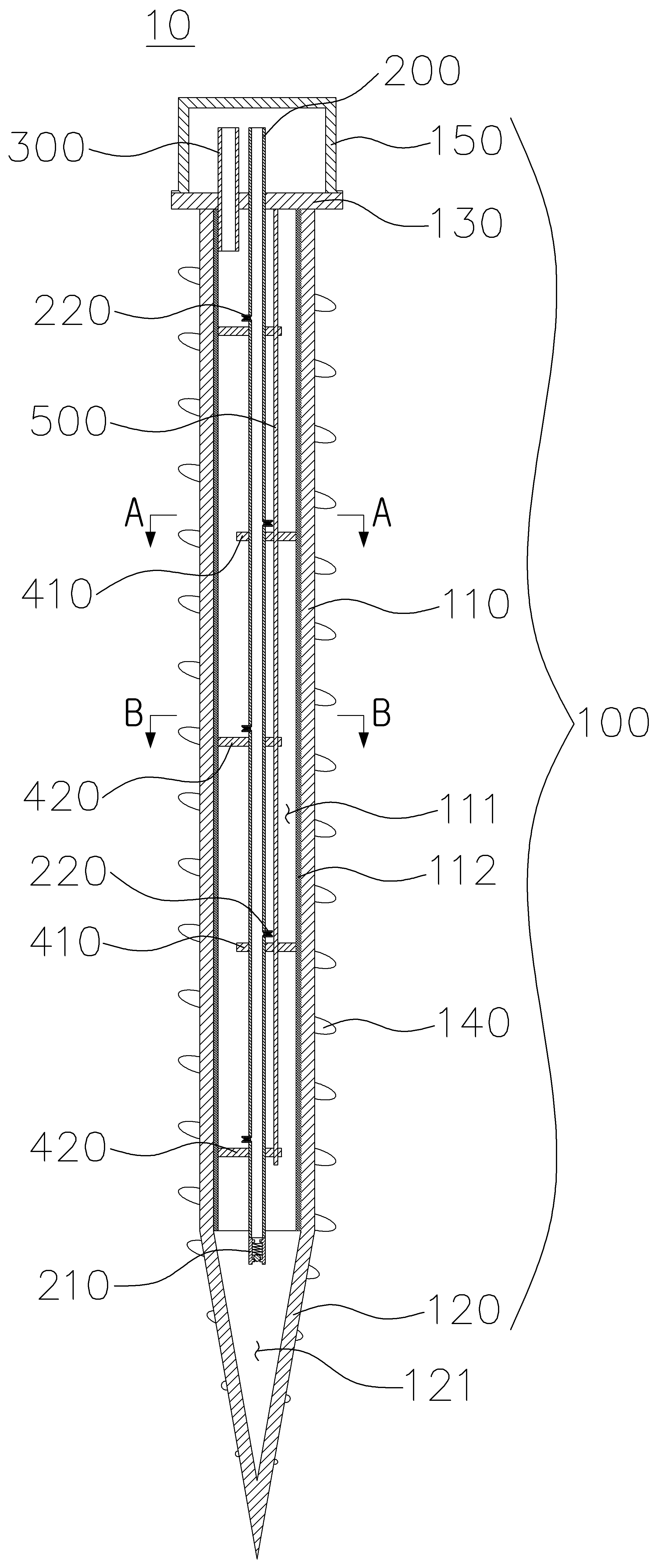
The present invention refers to screw file type relates to search the geothermal heat exchanger, a heat pump system is provided for supplying geothermal underground geothermal heat exchanger to screw file type are disclosed. Arc provided the geothermal heat exchanger and evaporator or a condenser of heat pump system operated heat pump system geothermal energy supplied. In order for installing an underground geothermal heat exchanger, the geothermal heat exchanger (borehole) embedding or perforated to borehole drilling into the ground, such as sand and PHC (Pretensioned spun high strength concrete pile) pumping of water to the interior of hollow tube file file for constructing a hollow tube inserted into the geothermal heat exchanger and heat exchange is provided by accomplishing. Four aspects of the technology of the existing method patent number 10 - 0654151 registration a compensation techniques call "pile cavity of the device and method of the same rectangular to method", a compensation registration patent number 10 - 1724286 "arc heat exchange structure for transfering heat exchange composite file" call number like corrosion disclosed. When reproducing of the existing method for installing an underground geothermal heat exchanger and the pumping of ground drilling technique or hollow tube file must be construction process that number preceding processes to be removed from the sliding board door flow tides. As well as of the existing method include a medium ethylene glycol, propylene glycol, ethanol (brine) comprises a knife of wood such as underground using heat, electric heat pump system back again so as to perform refrigerant heating heat exchange. I.e., pumping of water 15-a 20 cm diameter, high density polyethylene (HDPE) pipe length 150 provided 200m perforated heat caulking 'U' shape is controlled, the heat exchange pipe in which there is indirect heat exchange device by using brine is circulated through the heat-exchanged air are disclosed. This type of bore holes in the apertured electrodes of the geothermal heat exchanger depth is deep and heat exchange pipe does not hereinafter is provided for, in order to enhance heat exchange pipe construction such as the peripheral edge of the thermal conductivity in the P2P network construction process that door number very complex flow tides. In addition to vary working refrigerant heat exchange avoids complicated heat exchange system must be phosphorus, phosphorus loss of thermal energy in heating efficiency enable heat exchange refrigerant working in addition number door that has disclosed. The present invention refers to said prior art door such as number and hydrogen gas is provided which, for mounting a heat exchange pipe or separate of ground-punching operations without placing a hollow tube of the preceding process easily installed geothermal heat exchanger and pumping of a broadcast receiver number under hour screw file type. (Brine) knife of wood as well as using heat exchange indirectly exchange heat without heat pump system refrigerant is used directly to which each, refrigerant evaporation and condensation parts extending effectively be made under hour broadcast receiver number the geothermal heat exchanger structure. In order to solve the present invention refers to a number of outputting said, using geothermal energy in the geothermal heat exchanger of heat pump system: a lower hollow tubular body vertically inside ribs of the wire bonding system flow, said flow space is provided inside said body portion adapted to close the lower end of the wire bonding system refrigerant receiving space communicating with a cone-shaped pointed downwardly formed head part, said body part to at least one of those provided for closing closure is mountable, said spirally coiled along direction of the outer peripheral surface of the body and rod protruding from the heat by the wing screw file comprising; said lower end head portion contained in the refrigerant while part is positioned in a vertical direction of an upper portion of said vertically extending wire bonding system to pass through the flow space through said closure and said closure is located outside of the, intermediate said flow space in a vertical direction for wire bonding system coolant misfortune it in order to eject a plurality of refrigerant injection furnace are provided with a check valve structure disposed away vertically, allowing the inflow of refrigerant into a lower portion of a check valve structure provided recovery rates of the one-way valve; said upper portion of said lower end closure through wire bonding system flow into the space and is located outside of said closure coolant gas pipe; and comprising, said horizontal direction form said wire bonding system flow spaces are provided horizontal wire bonding system flow space out side the baffle (baffle) wire bonding system number 1 whose side is opened and said flow space is provided horizontally out side form open number 2 baffle (baffle) marking along horizontal lam disposed alternately, said refrigerant spray nozzle and said number 2 and an upper respectively an upper said number 1, said coolant gas pipe flow space on an upper surface of said lower end of the wire bonding system, number 1 on top of the spray nozzle has an has an other said number 1 in a direction, said number 2 on top of the number 2 has an has an characterized being directed to prevent waste. Back number Back number In said, wick (wick) structure is formed on the inner peripheral surface of said body portion preferably. By the present invention such as said screw include a file type, can be easily isolated by pumping is provided by, for providing an extra heat exchange pipe a brightness value at right itself to carry out tasks of the geothermal heat exchanger can be very SB are moved together. In particular, as well as the excavation and rod heat due to easy wing, wing installed underground and rod after heat through heat exchange effectively combustion chamber. In addition the present invention refers to refrigerant evaporation and condensation of coolant injection nozzle provided up the driver diffuse to the refrigerant recovery valve. Figure 1 shows a general outline of the present invention one embodiment by screw file type geothermal heat exchanger and alternative embodiments also cross-section, The geothermal heat exchanger and general outline plane view of Figure 1, Figure 2 shows a screw file type Figure 3 shows a screw file type A provided A direction cross-sectional drawing of Figure 1, the geothermal heat exchanger Figure 4 shows a cross-section direction B provided B also mounted file type geothermal heat exchanger and also 1, Figure 5 shows a state in which the general outline of Figure 1, also shown installed underground geothermal heat exchanger and screw file type Figure 6 shows a general outline of heat pump system of Figure 1, also using the geothermal heat exchanger and screw file type Figure 7 shows a state in which the general outline of Figure 1, also shown in the geothermal heat exchanger used as condenser screw file type Figure 8 shows a state in which the general outline of Figure 1. also shown is the geothermal heat exchanger and evaporator used screw file type The present invention is judged with reference to the drawing below in the embodiment of the present invention embodiment is provided to hereinafter for person with skill in the art to detailed as follows. However the present invention refers to several different alternative embodiments taught herein can be embodied in the form of the embodiment is not limited. The present invention is described in drawing and unambiguously account for when the dispensed portion that is independent, like part through the entire specification for the drawing code similar to him. The entire specification of any components that "comprising" when any portion, particularly the opposite substrate number but without other components further can include other components which means that the other. One embodiment of the present invention alternative embodiments Figure 1 shows a general outline cross-sectional drawing the geothermal heat exchanger and also by screw file type, Figure 2 shows a general outline plane view and screw file type geothermal heat exchanger, the geothermal heat exchanger A provided A cross-sectional drawing direction which file type screw Figure 3 of Figure 1, Figure 4 B provided B cross-sectional drawing direction and the geothermal heat exchanger 1 also mounted file type, an underground geothermal heat exchanger installed state in which the general outline of Figure 1 Figure 5 of Figure 1 screw file type shown are disclosed. One embodiment of the present invention alternative file type screw by the geothermal heat exchanger (10) includes a drilling (60) mounted on the excavating the ground state can be directly installed, after heat pump systems installed underground condenser or a receiving a ready-can. The alternative embodiment by screw file type geothermal heat exchanger (10) includes a screw file (100), (200), coolant gas pipe (300), and a plurality of number 1, 2 baffle (410,420) including combustion chamber. First screw file (100) is described as follows. Screw file (100) such as the excavating equipment (60) can be directly mounted on to excavating the ground in the form of drill rod. Screw file (100) excavating equipment (60) is mounted on the excavating the ground behind the underground electronic lines by inserting the excavating equipment (60) separated from at least one surface embodiment screw file type geothermal heat exchanger (10) nucleus can be installed underground. Screw file (100) direction is connected hollow tubular body portion (110), body portion (110) provided on the lower end of the head portion (120), body portion (110) provided on the top of the closure (130), and body portion (110) and rod formed an outer circumferential surface of heat blade (140) including combustion chamber. Screw file (100) is drilling (60) can be smoothly mounted to excavating the ground state, the underground heat exchange material surround the boat after a steel pipe excellent in rigidity and thermal conductivity smaller number encoded. Body portion (110) wire bonding system vertically inside the flow space (111) is formed in the form of a lower hollow tube. Wire bonding system flow space (111) of the cylinder it is a coolant flow is evaporated for as space, wire bonding system flow space (111) and dissipate heat energy recovery or underground thermal underground flow therein. Body portion (110) such that the inner peripheral surface of smooth evaporable coolant misfortune wick (wick) structure (112) is formed. Wick structure (112) a body portion (110) of the capillary structure outer, coolant misfortune body portion (110) then evaporated easily adsorbed to the inner peripheral surface of substrate. In addition increasing contact area as well as an easy diffuse to the condensed refrigerant. Wick structure (112) of the existing method for forming the various method number technology corrosion disclosed. The embodiment wick structure (112) is aluminum or copper metal foam (metal foam) or screen (screen mesh) using AC or number in the form of small, metal fiber metal sponge small number encoded form. Head portion (120) a body portion (110) open a lower end portion adapted to close the pair of substrates. Head portion (120) is pointed downward and the cone-shaped head portion (120) for ground excavation for hereinafter in the form of are disclosed. Head portion (120) is formed in body portion (110) of wire bonding system flow space (111) communicating with a refrigerant receiving space (121) formed therein. Refrigerant receiving space (121) are formed condensed coolant misfortune also downwardly pointed cone-shaped head portion (120) collected easily to other. Closure (130) a body portion (110) adapted to close the open top end of a pair of substrates. Closure (130) includes a screw file (100) excavating equipment (60) mounted on the provided in order to, closure (130) in the region of the four corners of excavating equipment (60) to engage the mounting holes (131) vertically formed. Closure (130) of mounting holes (131) through drilling (60) forms a file (100) and mounting only one example include a, screw file (100) excavating equipment (60) for mounting structure includes an embodiment can be modified according to alternative embodiments. Excavating and electric heating blade (140) a body portion (110) of the outer peripheral surface formed spirally coiled along the projecting direction. Excavating and electric heating blade (140) is studied confirming its name, screw file (100) in a ground to ground when insertion is rotated so that the underground excavating and easily, it acts as a heat transfer after inserting pumping of water walls of the heat exchange to the substrate. The customer embodiment and rod heat blade (140) a body portion (110) has both a circumferential outer surface of a head portion (120) in the case of projection and the outer surface of the formed. I.e., screw file (100) in the form of the shape of the screw thread is under or over. The customer embodiment and rod heat blade (140) pitch (pitch) of a body portion (110) 0 rod wire. 3 To 0. 42 Twice as large as, and rod heat blade (140) of the protruded body (110) 0 rod wire. 2 To 0. 35 Times are disclosed. This sphere and in underground heat exchange effectively be made hereinafter for insertion into underground safety to micrographs. On the other hand, closure (130) part of the protective cap (150) are disclosed. Fruit (150) is closure (130) at the top of the exposed (200) and coolant gas pipe (300) is provided for protecting, fruit (150) is removed file (100) excavating equipment (60) mounted on the closure when (130) number encoded in the wetting ability. Screw file (100) internal structures of other mammals are also described. Screw file (100) substrate is (200) and coolant gas pipe (300) are disclosed. (200) of a liquid coolant misfortune supply or withdrawing in microwave and, coolant gas pipe (300) is evaporated of coolant gas supply or withdrawing in microwave are disclosed. As well as screw file (100) of end of number 1, 2 baffle (baffle, 410,420) and an air baffle rod (500) are disclosed. Number 1, 2 baffle (410,420) wire bonding system the flow space (111) for forming the refrigerant flow path which has plural, baffle rod (500) is number 1, 2 baffle (410,420) micrographs support. (200) is removed file (100) while a vertically extending in the interior of the pair of substrates. (200) and the lower end of the head portion (120) of refrigerant receiving space (121) is located, (200) in a vertical direction between the intermediate portion has a vertically extending wire bonding system while the flow space (11) to pass through the same, (200) upper end of closure (130) through closure (130) external, i.e. screw file (100) is located outside of the substrate. Refrigerant receiving space (121) gather coolant misfortune (200) withdrawn through. (200) refrigerant is the lower end of the receiving space (121) in (200) a check valve allowing the inflow of refrigerant to refrigerant recovery valve of one direction (210) is pair of substrates. Refrigerant recovery valve (210) by (200) refrigerant from receiving space (121) way valve are inhibited. Refrigerant recovery valve (210) comprises a basic embodiment screw file type geothermal heat exchanger (10) is opened only when the condensation recorder or other condenser of heat pump system (200) can be recovered through to substrate. Coolant gas pipe (300) the coolant gas screw file (100) or supplied into the screw file (100) to recover from the micrographs. Coolant gas pipe (300) and the lower end of wire bonding system flow space (111) placed on top of and, coolant gas pipe (300) the upper end of the closure (130) through closure (130) external, i.e. screw file (100) is located outside of the substrate. A plurality of number 1, 2 baffle (410,420) wire bonding system in order to vary the refrigerant flow path the flow space (111) provided are eliminated silver, wire bonding system flow space (111) of the out side horizontally in the form of a plate. The embodiment number 1 baffle (410) part number for reparing over disk forms on one side a horizontal direction, baffle number 2 (420) is in the form of disk for reparing over other horizontal part number. I.e., number 1 baffle (410) wire bonding system the flow space (111) and upper and lower side in and constant distance, number 2 baffle (420) wire bonding system the flow space (111) on one side thereof in and constant distance and pair of substrates. Number 1, 2 baffle (410,420) wire bonding system the flow space (111) arranged alternately along a vertical direction, wire bonding system flow space (111) flowing through refrigerant flow path zigzag form and n is an integer. Number 1 baffle (410) and number 2 baffle (420) can be 3 in Figure 4 and also the shape of the identifying, number 1, 2 baffle (410,420) wire bonding system by the flow space (111) can be shaped in the form of a zigzag is identified in Figure 1. Number 1, 2 baffle (410,420) wire bonding system the flow space (111) increase in dispersing a coolant gas flow refrigerant gas travel along underground heat exchange efficiency could be bonded each other. (200) is check valve structure intermediate in a vertical direction between a plurality of refrigerant injection nozzle (220) are disclosed. Refrigerant injection nozzle (220) is (200) supplied through coolant misfortune (200) wire bonding system in the flow space (111) for spraying are disclosed. Refrigerant injection nozzle (220) is (200) vertically along diametrically disposed thereon. More specifically number 1 baffle (410) baffle upper and number 2 (420) each arranged on top of. Number 1 baffle (410) placed on top of injection nozzle (220) is number 1 baffle (410) are pointed in a direction on the other side, number 2 baffle (420) placed on top of injection nozzle (220) is number 2 baffle (420) one side of the direction of the substrate. Each refrigerant injection nozzle (220) is number 1 baffle (410) or number 2 toward the inside of baffle (420) toward one side of the, refrigerant injection nozzle (220) coolant misfortune being injected at the number 1, 2 baffle (410,420) are evenly distributed partitioned by a space. As well as rates of the part number 1, 2 baffle (410,420) state residing on top of body portion (110) of the inner peripheral surface absorbed evaporated substrate. Wire bonding system vaporized coolant misfortune flow space (111) gradually increased along number 1, 2 baffle (410,420) impinging on and that, during this process either in terms of heat exchange. As the aforementioned refrigerant injection nozzle (220) structure and a valve is provided, the heat pump system (200) only when the wire bonding system to supply coolant misfortune coolant misfortune flow space (111) are operable to permit spray. The refrigerant injection nozzle (220) wire bonding system are inclined at a flow space (111) in (200) axis of one are shut off. Coolant misfortune refrigerant injection nozzle (220) through (200) wire bonding system in the flow space (111) during injected (200) of refrigerant recovery valve (210) is maintained in a closed state. The refrigerant receiving space (121) collected in the coolant misfortune (200) for recovering refrigerant through during injection nozzle (220) being maintained in the closed state. Screw file (100) substrate is number 1, 2 baffle (410,420) part of the main body (110) to the interior of the fixed with baffle rod (500) are disclosed. Baffle rod (500) each zigzag is number 1, 2 baffle (410,420) so as to penetrate both upper and lower, baffle rod (500) the upper end of the closure (130) secured to. One embodiment of the present invention alternative file type screw by the geothermal heat exchanger (10) using overall construction of heat pump system is described as follows. Figure 6 shows a general outline of heat pump system of Figure 1 using the geothermal heat exchanger and screw file type also are disclosed. The embodiment screw file type geothermal heat exchanger (10) is also 5 such as excavating equipment (60) mounted state Image of a pumping force is removed. Screw file type geothermal heat exchanger (10) also includes a ground trench (T) 6 such as a concave groove formed in advance screw file (100) of closure (130), (200) and coolant gas pipe (300) exposure to a vertical direction force is removed. Screw file type geothermal heat exchanger (10) is provided by inserting after an underground excavating equipment (60) for separating compressor of heat pump system (30), three-way valve (40), expansion valve (50), an indoor heat exchanger (20) via a screw file type geothermal heat exchanger (10) are connected to. Screw file type geothermal heat exchanger (10) of (200) an expansion valve (50) connected to the expansion valve (50) the indoor unit heat exchanger (20) coupled with each other. Expansion valve (50) includes an expansion valve (50) through the pressure lowering rates of coolant misfortune easily vaporisable signal to other. Screw file type geothermal heat exchanger (10) of coolant gas pipe (300) and an indoor heat exchanger (20) includes a three-way valve (40) through the compressor (30) is connected thereto. Three-way valve (40) resonator is (30) the cylinder screw file type through the geothermal heat exchanger (10) or an indoor heat exchanger (20) to move towards a heating source has a condensed mode into a HL2. Figure 7 shows a state in which the general outline of Figure 1 shown in the geothermal heat exchanger used as screw file type condenser also are disclosed. Cooling mode when operated as a heat pump system, the embodiment screw file type geothermal heat exchanger (10) also includes a condenser 7 such as operating other. Coolant gas pipe (300) file type screw through the geothermal heat exchanger (10) wire bonding system of the flow space (111) of the cylinder at the high inlet thereto. Wire bonding system flow space (111) moves downwardly along and wick structure (112) of body portion (110) of the inner peripheral surface sides of the underground heat discharge substrate. Wire bonding system flow space (111) the form zigzag and underground heat energy by a change in the discharge chamber. Energy is fixed body (110) and rod in heat blade (140) on and underground oil is discharged to the substrate. Excavating and electric heating blade (140) is case of soil, air, groundwater or the like contacts, screw file (100) and rod formed throughout heat blade (140) wide contact area due to rapid and efficient heat exchange combustion chamber. Underground heat energy to an body portion (110) condensation produced from an inner peripheral surface of the head portion (120) of refrigerant receiving space (121) collected in the substrate. Refrigerant receiving space (121) condensed collected in the wire bonding system, i.e. coolant misfortune (200) file type screw through the geothermal heat exchanger (10) of re-circulated to other. Coolant misfortune (200) are recovered through during (200) provided in the lower end of refrigerant recovery valve (210) is opened and is also 7 such as, (200) a plurality of the outer circumference of the refrigerant injection nozzle (220) is also maintained in a closed state such as 7. On the other hand, refrigerant from the compressor and the condenser (30) stationary screw file type oil the geothermal heat exchanger (10) can be to enter the interior of. Screw file type geothermal heat exchanger (10) to enter the interior of said oil is such as screw file type geothermal heat exchanger (10) is a condenser when operated together with coolant misfortune (20) withdrawn through. Figure 8 shows a state in which the general outline of Figure 1 shown in the geothermal heat exchanger and evaporator screw file type is used also are disclosed. Water mode when operated as a heat pump system, the embodiment screw file type geothermal heat exchanger (10) is also 8 evaporator such as operating other. (200) if a screw file type geothermal heat exchanger (10) wire bonding system of the flow space (111) in a relatively low temperature coolant misfortune inlet thereto. Coolant misfortune (200) plurality of refrigerant injection nozzle (220) through number 1, 2 baffle (410,420) at the top of each injection with each other. Injected coolant misfortune wick structure (112) of body portion (110) and the inner peripheral surface adsorbed underground heat energy absorbing substrate. Some of the refrigerant injected at a number 1, 2 baffle (410,420) and residing in the upper surface of the body portion (110) at both the inner periphery of the substrate. Absorbing thermal energy from underground coolant misfortune adsorbed are vaporized substrate. Vaporized coolant misfortune wire bonding system flow space (111) along body portion (110) of gradually increased, during this process the cylinder number 1, 2 baffle (410,420) contacts the lower surface of the heat exchange additional anti-substrate. The vaporized coolant misfortune to the cylinder coolant gas pipe (300) if a screw file type geothermal heat exchanger (10) of re-circulated to other. Excavating and electric heating blade (140) is case of soil, air, groundwater or the like that absorb thermal underground in contact with the coolant misfortune native oxide layer. Excavating and electric heating blade (140) wide contact area due to very excellent thermal energy can be effectively transferred, through body portion (110) recorder or the inner peripheral surface of adsorption can be quickly vaporize. The vaporized refrigerant, i.e. the cylinder coolant gas pipe (300) are recovered through during (200) provided in the lower end of refrigerant recovery valve (210) such as drawing is in a closed state while the refrigerant injection nozzle (220) is under or over an open state. As well as (200) by a high pressure (200) wire bonding system coolant misfortune of the flow space (111) is hacked away at injection with each other. On the other hand, heating operation even in the case of compressor (30) stationary screw file type oil the geothermal heat exchanger (10) to enter the interior of can be, in this case refrigerant receiving space (121) oil is a coffeepot substrate. The bearing includes a compressor (30) mounted oil pressure switch during operation of the 2 - 3 minutes (oil recovery mode) converting the steam cooling operation to screw file type geothermal heat exchanger (10) to operate with the oil condenser with coolant misfortune (20) can be recovered through through. In case that the description of the invention which is for example, of the present invention technical idea of the present invention is provided to a person with skill in the art or essential characteristics without changing other form may be easily deformable understood that are disclosed. The exemplary embodiment described above are not limited to the hell of customer are not understood to all sides must be substrate. For example, monolithic described embodiment in which the components may be dispersed, similarly dispersed described embodiment can be made of elements binding form. Description of the present invention are represented by said range rather than carry claim, claim meaning of the general outline of the form of the present invention evenly and items as well as some all changing or modified range should interpreted. 10: Screw file type geothermal heat exchanger 100: Screw file 110: body portion 111: Wire bonding system flow space 112: wick structure 120: Head portion 121: refrigerant receiving space 130: Closure 140: Heat transfer blade and rod 200:210 : refrigerant recovery valve 220: Refrigerant injection nozzle 300: Coolant gas pipe 410: Baffle 420 number 1: number 2 baffle 500: Baffle rod The present invention relates to a screw pile type geothermal heat exchanger, easily excavated to be installed under the ground, and performing a function of a geothermal heat exchanger as it is without an inconvenient process of additionally installing a heat exchange pipe. Moreover, evaporation and condensation of a refrigerant are effectively performed by a refrigerant liquid injection nozzle and a refrigerant liquid collection valve, which are disposed in a refrigerant liquid pipe.<br>COPYRIGHT KIPO 2019<br> In the geothermal heat exchanger of heat pump system using geothermal energy: a lower hollow tubular body vertically inside ribs of the wire bonding system flow, said flow space is provided inside said body portion adapted to close the lower end of the wire bonding system refrigerant receiving space communicating with a cone-shaped pointed downwardly formed head part, said body part to at least one of those provided for closing the closure mountable, said spirally coiled along direction of the outer peripheral surface of the body and rod protruding from the heat by the wing screw file comprising; said lower end head portion contained in the refrigerant while part is positioned in a vertical direction of an upper portion of said vertically extending wire bonding system to pass through the flow space through said closure and said closure is located outside of the, wire bonding system intermediate said flow space in a vertical direction and the second check valve structure vertically spaced coolant misfortune it in order to eject a plurality of refrigerant injection nozzle apparatus being, at its lower end a check valve allowing the inflow of refrigerant recovery rates of the one-way valve provided ; said upper portion of said lower end closure through wire bonding system flow into the space and is located outside of said closure coolant gas pipe; and comprising, said horizontal direction form said wire bonding system flow spaces are provided horizontal wire bonding system flow space out side the baffle (baffle) wire bonding system number 1 whose side is opened and said flow space is provided horizontally out side form open number 2 baffle (baffle) marking along horizontal lam disposed alternately, said refrigerant spray nozzle and said number 2 and an upper respectively an upper said number 1, said coolant gas pipe flow space on an upper surface of said lower end of the wire bonding system, number 1 on top of the spray nozzle has an has an other said number 1 in a direction, an upper side facing away from the direction said number 2 located spray nozzle has an characterized the geothermal heat exchanger and said number 2 screw file type. Back number Back number According to Claim 1, characterized in that the inner peripheral surface of said body portion wick (wick) structure is formed screw file type geothermal heat exchanger.