PNEUMATIC TRAIN MODEL DRIVING TEST APPARATUS APPLYING HIGH-SPEED VALVE
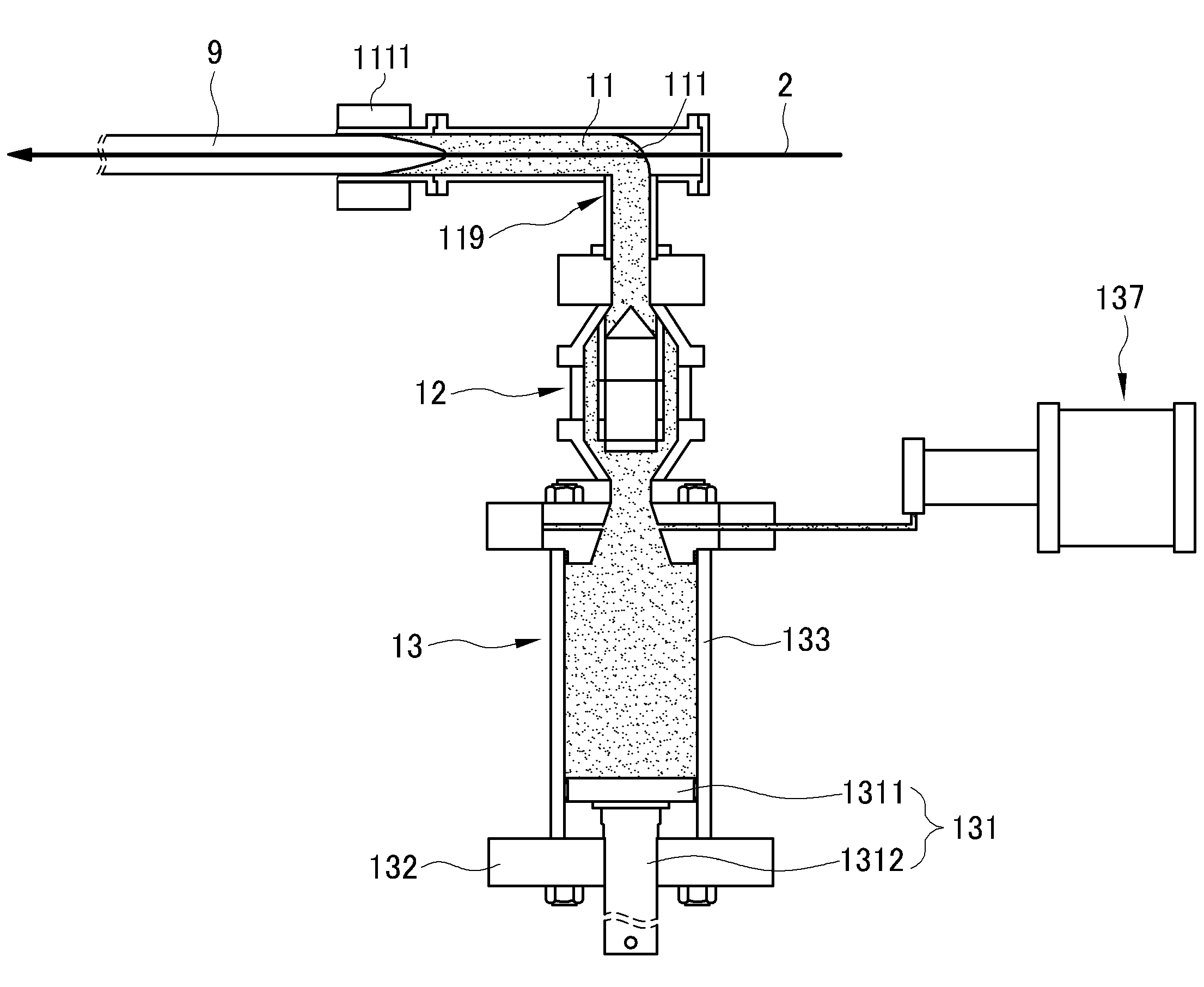
Running test model a nickel aluminide covered material herein relates to device, more specifically a pneumatic applying a very high speed valve train relates to running test model device. Generally, trolley for running test, a tunnel running test model train the sidewalls of the storage space may be used is device. One example of device running test model train such the applicant a registration call and patent number 0367627 the bar number 0389164 call. In testing machine model train constitution: a single pixel of a, projectile structure a rupture diaphragm valve using projectile shooting model train a pressure. Such projectile in testing machine model train structure was significantly useful. However, according to recent trend, train of arranging the active mode, and for conserving and weight is increased, pressure projectile projectile can be improved a frame counter requires structure is. Furthermore, existing Invar manner air gun structure relates to a bullet, rate between the right side and the mother pipe having a cross sectional shape, or a fragment thereof, such that an aft portion of train type of models thereof running test is enabled, train of models thereof, such that an aft portion small outer diameter body a a streamline running test could not be applied to the model train. A heavy weight train model, model train knitting large amount, body the circumstance plane a streamline, such that an aft portion modeling and a nickel aluminide covered material a train of models thereof running test model train possible to travel test device, intended for to provide a. Said techniques, the first and techniques for achieving as means, herein include a device number 1 side according to running test model train, train model; said train model propel the projectile structure; and a shock absorber is made of model train said braking unit includes, said projectile structure, model train said one end in which the projectiles are fired from having pressure in a direction towards one end said propagation of projectile formed among the plurality of surfaces of an acceleration tube; said train model shooting pressure are filled in the housing including pressure chamber unit; said reaction end and end of said projectile and the other end is is connected to one end of the housing said housing pressure in piston valve delivering mouth and which are in said projectile (cylinder valve) may include a unit. Aforementioned according to constitution of herein, pressure chamber unit into a housing containing a light transmitting pressure piston valve unit by an aperture acceleration tube wherein delivery mouth and which are in relates to a bullet, heavy weight train model, body the circumstance plane train knit and a volume model a nickel aluminide covered material of models thereof. body such that it can travel test. Figure 1 shows a model train aspect embodiment of WIPO each configuration navigation system to illustrate the arrangement relation of the approximate general outline is for. The projectile according to Figure 2 shows a embodiment of WIPO multiplex structure is cross-sectional. Figure 3 shows a the housing, air booster pump and an air compressor for driving to explain the process the approximate general outline is. According to embodiment of Figure 4 shows a WIPO a propellant is mounted a thermal shield that is shown in the model is cross-sectional coarse. Figure 5 shows a propellant: an embodiment of WIPO multiplex cross-sectional is (sabot). Figure 6 shows a embodiment of WIPO: an propellant recovering section to describe the acceleration tube before the projectiles are fired from having model train, dump tank and propellant recovering section it is shown a is cross-sectional a coarse. The enlargement of a Figure 7 shows a VII is the approximate cross-sectional drawing of Figure 6. Figure 8 shows a disposed on a structure also herein speed reducing: an embodiment of multiplex structure is aspects. Figure 9 shows a speed reducing: an embodiment of WIPO of is the approximate front. Figure 10 shows a WIPO embodiment of aspect a speed that depends sensor on support structure to describe the speed sensor is arranged in a a is shown that is the approximate general outline. Figure 11 shows a WIPO: an embodiment of sensor of disposed to describe the support structure is arranged in a sensor section on a is shown that is the approximate general outline. Under reference to the drawing based on a text content of the herein in is in the field of the person with skill in the art easily embodiment embodiment a can be. as further described thereby, the cold air flows. However a variety of different is embodied in the form described where can be embodiment aspect is not limited. In drawing and herein described thereby unambiguously direct the portion that are independent of and described for the, specification similar parts throughout the drawing similar to he glued his code. Specification in an entire herein, certain with distinct portions of the emitting surface when seat but invisible from the driver are "connected", the "connected directly" as well as when, its intermediate separating members, wherein another element is "electrically connected" includes a double-is. Specification in an entire herein, any member is "on" the other member when to be located, is any member is when the other member is in contact with a between the two members as well as the presence of another member includes even in the case. Specification in an entire herein, certain on any configuration element when advisable to "includes", is especially opposite the substrate to which it is-free other features element is supported by the upper case and, excepting the other further include components to. meaning that it may be set. Herein used in entire specification of such a magnitude that induces terms "about", "substantially", or the like, that has unique to the meanings cited in manufacturing and material which the tolerance to be presented when at or values is used the widest sense of the proximity levels in relation to, to aid the comprehension of herein or an accurate absolute is numerical-is-mentioned disclosure content is per ' iphery of wrongly self conscience non use is used for the prevention of. Entire specification of such a magnitude that induces terms herein used in "-(a) step" or "-step" the "steps for-" does not mixture by the addition of an initiator. With reference to, exemplary embodiment herein include a description in terms related to the position directional or multi-directional (once, one end, the other end, such as other end) consists of a piston valve unit based on the combined with acceleration tube to an internal bottom surface of the one side. is welded to the loading. For example piston valve when saw 2 and 1 (cylinder valve) unit based on the side of the body side combined with acceleration tube, on one side thereof and generally in such a manner that the end once, generally a portion the one end part on one side thereof and, piston valve unit reference the pressure chamber unit is combined with other, generally, other end in such a manner that the end droop, magnetically overall toward an expanded metal, and the sections can be other end, and the like. Running test model a nickel aluminide covered material herein relates to device. In hereinafter, herein: an embodiment of device running test model train (hereinafter 'the present train model running test device' assembling and welding steps) relates to. Figure 1 shows a model train aspect embodiment of WIPO each configuration navigation system to illustrate the arrangement relation of the approximate for concept and, herein according to embodiment of Figure 2 the projectile is cross-sectional multiplex structure. With a 1 also, the present train model travel test model a train device (9), train model (9) the projectile structure (1) and train model (9) a shock absorber is made of braking structure (3) includes. Also 1 with a, projectile structure (1) for traveling fired by the a train model (9) absorbing an impact for braking structure (3) by reaches, a truck's travelling may be carried out. Furthermore, also with a 1, the present train model running test device a train model (9) moving path is disposed along a wire rail a steel wire (guidance wire of train model) (2) may comprise an. Train model (9) the steel wire rail wire (2) is connected to wire rail steel wire (2) can be traveling along. Furthermore, also refers to surface 1 and 2, projectile structure (1) once the model train unit (9) towards one end which the projectiles are fired from having propagation of pressure in a direction opening projectile (111) is formed an acceleration tube (11), train model (9) fire pressure are filled in the housing including pressure chamber unit (13) and end acceleration tube (11) relates to a bullet opening (111) end of the rotor shaft and the other end is pressure chamber unit (13) housing (133) is connected to one end of, housing when opened (133) opening fire pressure in (111) the delivery of the piston valve (cylinder valve) unit (12) includes. Pressure chamber unit (13) can be is filled the pressure in, piston valve unit (12) is opened, filled pressure instantaneous acceleration of the tube (11) relates to a bullet opening (111) and passed to the. Transmitted pressure fired by the opening (111) disposed to one end of model train recorded in the machining program (9) include a launch can be. According to device running test model train of the existing method, temperature goes to broken by the fired compressed air disrupted, causing them to layer within the tube a train model accelerating the been a rupture diaphragm valve is applied. The, train of models thereof, and the path for accelerations of compressed air not disruption of layer broken by the air, compressive forces that the been to, eventually, model train weight, running test of models thereof train knitting large amount was is difficult. However, the present train model according to running test device, piston valve unit (12) the pressure destroyed by the liquid crystal panels is not the active mode, and for conserving, the piezoelectric pump can have high pressure projectile, very high speed into an open position thereof about a a piston valve unit (12) of openings only is formed in and instant acceleration of the tube (11) be capable to deliver the reactant to. The, the present train model according to running test device, maximum projectile pressure, train model (9) can be the maximum. Illustratively, device according to running test model train of the existing method, maximum projectile cd1a. pressure is 20 bar, but is 1 kg weight maximum of models thereof train, the present train model according to running test device, maximum projectile can be increasing pressure 50 bar, train model (9) maximum weight 5 kg. increases. The present train model running test device associated with the configured specifically for longitude and equal. Also refers to surface 2, pressure chamber unit (13) pressure are filled in the housing (133) amount of the pressure and filling that vary volume variable region (131) may comprise an. Illustratively, housing (133) an inside diameter of 200 mm, length 320 mm can be made of the. Furthermore, housing (133) a maximum pressure to a pressure of at least 60 kg/cm2 to enhance stability, a key may be fabricated. Furthermore, housing (133) on the inner faces of the plates in the manufacture process [...] (reaming) can be carried out. Furthermore, housing (133) the pressure sensor and safety valve for. may be provided. Furthermore, housing (133) on the intermediate portion and the for measuring pressure of be. Illustratively, housing (133) in the 2 minutes preferably 0.01 kg/cm2. Furthermore, housing (133) the pressure in the train model (9) relates to a bullet speed (highest shooting speed of a electric * 0.5% shooting speed of a electric highest+)can be is so controlled as to have. Illustratively, train model (9) relates to a bullet and 5 L volume of a pressure chamber speed, train model 6 amount can be 600 km/h to knit 1. Furthermore, illustratively, also 2 as demonstrated, volume variable region (131) the, housing (133) at the surface where the filling pressure is interior of section (1331) and filling section (1331) capable of varying volume of section out (1332) and a fill section and an additional section is divided into the high lift portion is movable between the fluorescent layer (1311) and (1311) the housing from (133) of outwardly extending rod (1312) may comprise an. 2 also refers to surface, partition (1311) additional section (1332) into surface, filling section (1331) volume of the. can be increased. Furthermore, partition (1311) is filled section (1331) into surface, filling section (1331) volume of the can be reduced. Illustratively, filling section (1331) can be 10 L maximum volume. Furthermore, also refers to surface 2, partition (1311) movement of rod (1312) .may be brought about by movement of. In other words, , rod (1312) additional section (1332) side or fillers section (1331) into surface, rod (1312), which are connected with the partition (1331) by, filling section (1331) .can be made variable volume of. Also as demonstrated 2, rod (1312) the housing (133) other section of (132) can be-emitting device. Furthermore, housing (133) located outside of a load (1312) on a part of controlling capacity can be equipped by handle (not shown).. Illustratively, TM Screw the handle by means of is able to. The, filling section (1331) .may be displayed in volume change in. Furthermore, volume variable region (131) the housing (133) pressure in the high pressure without leakage may include a u packing for. Figure 3 shows a the housing, air booster pump and an air compressor for driving to explain the process the approximate general outline is. Also 2 and 3 with a, pressure chamber unit (13) air booster pump (137) may comprise an. Air booster pump (137) the housing (133) may be connected to and. Illustratively, but not shown to prevent the 2 also, housing (133) of the door and a left (also 2 a, 9 in direction) and right (also 2 a, in direction 3) each air booster pump (137) preferably placed. The, housing (133) in compression and or more active and the body such that it can corresponding. Air booster pump (137) the housing (133) is selectively stored and to pneumatic may be provided to apply a.. In particular, air booster pump (137) according to, 10 bar a low low performing air compressor-power supplying unit are contained in a pressure chamber unit (13) housing (133) to 150 bar 15 times can be supply high pressure degree by using W metal. Generally, high performance air compressor which and inexpensive very large, in addition withstand high pressure up, along a guide rail to a pneumatic hose. However, the present train model according to running test device, air booster pump (137) by comprising a, in particular, air booster pump (137) the housing (133) and the nearest by comprising disposed in the casing so that the, low pressure the air booster pump (137) even air is supplied to air booster pump (137) high-pressure made housing (133) the active mode, and for conserving supplied to, generally to the current flowing in the, hose duct for infants can be of the length of. Furthermore, air booster pump (137) an air regulator may comprise an (Air Regulator). Furthermore, also with a 3, air booster pump (137) and the housing (133) for the pressure control the piping can be a valve is installed. The, housing (133) can be while pressure is adjusted in. Furthermore, also 2 and 3 with a, pressure chamber unit (13) an air compressor (air compressor) (139) may comprise an. In herein, housing (133) method compression in air booster pump (137) and an air compressor (139) can be performed by. Housing (133), air booster pump (137) and an air compressor (139) also process for driving 3 as shown in be. Furthermore, pressure chamber unit (13) may comprise an the muffler. The air booster operation of a pump can be remote device to. Furthermore, pressure chamber unit (13) may comprise an gauge pressure. Pressure gauge an air booster pump is supplied at pressure of the compressed air, can be shown. Furthermore, also refers to surface 2, acceleration tube (11) one end of the dump tank (1111) is installed at the. Dump tank (1111) has to an acceleration tube (11) if the lever is rotated right let one end of the acceleration tube (11) .and the tail gas burner can be a other official buildings. Such dump tank (1111) has resonant type muffler. capable, if required, of acting. Furthermore, illustratively, projectile opening (111) can be 60 mm the diameter of the primary drying chamber. Furthermore, acceleration tube (11) door has refers to surface 2, bent can be arranged. Also as demonstrated 2, acceleration tube (11) along which a member (119) by bending can be arranged. Furthermore, also as demonstrated 2, piston valve unit (12) cross-sectional area toward an end that one end of it approaches the light emission surface can be wedge shape. In other words, , piston valve unit (12) one end of the acceleration tube (11) toward. can be narrowed, and cross-sectional area. Furthermore, piston valve unit (12) and the accelerating tube (11) for improving ride comfort and in for joint of time, so as to cause neither to, of motor armature of peripheral an upper part of the electric member (121) is installed at the. Illustratively, member (121) can be the O ring. While, also refers to surface 2, piston valve unit (12) the vicinity of the second and a housing (133) at least more than one of said one end of toward the contact top of one another and the sectional. may be shaped in the shape of a wedge. The, pressure chamber unit (13) from piston valve unit (12) the pressure transmitting to. Furthermore, pressure chamber unit (13) and the piston valve unit (12) does not induce the occurrence of to for improving ride comfort and the connection between the can be made to be which, illustratively, housing (133) and the piston valve unit (12) for connection of bolt standard M20 can be used, such as, dog 8 can be used. Furthermore, housing (133) and the piston valve unit (12) that surrounds the splice of a can be which has one. Illustratively, from being permeated through [...] , may mount to O ring. Vacuum grease is can be used in addition. Furthermore, also 3 with a, piston valve unit (12) an air compressor (139) the item may be pressure driven from. Piston valve unit (12) and an air compressor (139) (Air Regulator) on the air gas supplying pipe for connecting a capstan which may be provided, the, piston valve unit (12) the air compressor (139) pressure from the live report during the game can be adjustable. Furthermore, illustratively, piston valve unit (12) may comprise an which a solenoid valve. The, piston valve unit (12) of apertures disposed therethrough closed (on/off (ON/OFF)) formed in an inside of switching, in a short time piston valve unit (12) can be opening and shutting a. With reference to, piston valve unit (12) the opening and closing of the control fluid can be. Or, housing (133) by the pressure in piston valve unit (12) can be opening and shutting a. This case, is minimized supporting the controller operates the pistons to valve unit (12) can be opening and shutting a. Such as that described above include a launch structure (1) according to, filling section (1331) maximum volume when 10 L, a shooting speed of a electric train of 2 kg can be 1,000 km/h of models thereof. Furthermore, the present train in running test model device, projectile structure (1) a base substrate can be disposed on. Projectile structure (1) correlation value is generated due to a flow of, projectile structure (1) a base substrate anchor bolt may be fixed into.. According to embodiment of Figure 4 shows a WIPO a propellant is mounted a thermal shield that is shown in the model the approximate cross-sectional drawing and, : an embodiment of Figure 5 herein multiplex propellant is cross-sectional. Also refers to surface 4, the present train a device running test model, model train (9), such that an aft portion of a propellant (5) may comprise an. Also 4 and 5 as demonstrated, propellant (5) one end of the train model (9), such that an aft portion of which engage the train model mounting portion (53) may be formed. Train model mounting portion (53) the CNC (Computerized Numerical Control) can be formed the processing. The, train model mounting portion (53) the maximum train model (9) of a bearing member corresponding to the shape of, such that an aft portion of can be formed. Furthermore, also 5 as demonstrated, propellant (5) the other end of the rear face depressions quantity capable of recording into curved surface (55) may be formed. The, propellant (5) opening include a launch rear end of (111) maximizes the from can be a. Or, the present train depending on use conditions of device test model, propellant (5) the launcher the rear end of opening (111) from of the case body to maximum pressure, propellant (5) can be plane surface. Illustratively, 4 and 5 also as demonstrated, propellant (5) the train model (9) body outer diameter (outer diameter) is accelerated tube (11) (inner diameter) inner diameter of when tight, contrast, such as, train model (9) body acceleration tube outer diameter (11) than the inside diameter of much when the amount of light concentrated on, train model (9) can be mounted. Illustratively, acceleration tube (11) and 60 mm internal diameter of, train model (9) when outer diameter of 58 mm can be mounted. Furthermore, model train (9), such that an aft portion of a streamline can be mounted when the. Furthermore, also 5 as demonstrated, propellant (5) acts catch and latch the refers to stepped catch segment is also provided with a catch (57) may include a. Also 5 as demonstrated, catch stepped (57) the propellant (5) projecting in the external direction, and along the outer circumferential surface of the can be formed. it does but to prevent refers to, propellant (5) the train model (9) immediately after relates to a bullet, catch stepped (57) is latch and by applying, train model (9) can be irregular in the disposition direction of the. Furthermore, also 5 as demonstrated, propellant (5) a vertical rib is to stick to an, upper piece (52) and lower piece (51) may comprise an. The, propellant (5) the train model (9) model train which does not interference during a traveling (9) can be is attaching. Furthermore, propellant (5) is made out of a MC (Monomer Caster) can be material. MC of propellant (5) the support frame the capacity ratio thereof can reach strength. Propellant (5) the train model (9) range which exerts no interference during a traveling weight thereof by in the, a key may be fabricated is set. Figure 6 shows a embodiment of WIPO: an propellant recovering section to describe the acceleration tube before the projectiles are fired from having model train, dump tank and propellant recovering section it is shown a cross-sectional drawing and the approximate a, the enlargement of a Figure 7 shows a VII is coarse cross-sectional of Figure 6. Also 6 with a, the present train a device running test model, model train (9) a irregular in the disposition direction of the propellant (5) is recovered to, acceleration tube (11) pre-side of one end is and extend for a length, said acceleration tube (11) a train has been launched from the model (9) moving path to wrap the formed propellant recovering section (6) may comprise an. In other words, , also 6 as demonstrated, propellant recovering section (6) has dumping tank (1111) can be formed on one end of. Propellant recovering section (6) by propellant (5) model train is (9) when separated from, .can be recovered in the. Also as demonstrated 7, acceleration tube (11) one end of model train surface (9) of propellant during firing (5) model train is (9) to irregular in the disposition direction of the, projectile opening (111) along the external circumference of opening projectile (111) toward segment is also provided with a catch (113) may be formed. Latch (113) the latch catch stepped (55) and catch can act. More particularly, also 6 with a, train model (9) of during firing, propellant (5) catch stepped (57) the latch (113) can be latched onto. The, train model (9) of model train during firing (9) and propellant (5) can be the separated. Furthermore, with reference to, also 7 as demonstrated, acceleration tube (11) one end of latch surface (113) is an edge of (112) is installed at the. Latch (113) the base part (112) can be provided on.. Also 6 with a, propellant recovering section (6) the absorbent are formed on the inner faces of the plates (62) may comprise an. Specifically, also 6 as demonstrated, propellant recovering section (6) the train model (9) moving path surrounds a passage portion to (61) may comprise an. Furthermore, impact absorbent (62) passageway part (61) can be formed on the inner surface of. Impact absorbent (62) the train model (9) and propellant (5) when separated of model train (9) a separation from a propellant (5) is passage portion (61) and a when it strikes side of can be. Furthermore, passage portion (61) is made out of a propellant (5) by impact it does not break a protrusion/recess shape and are preferably which should be the same. Furthermore, also as demonstrated 6, passage portion (61) is provided at one end of the a train model (9) for passing through the outlet (63) the train model (9) the direction of progress of smaller from the lower portion to the central axis of the can be wedge shape. The, train model (9) separated from propellant (5) the outlet (63) through the being released to the outside at the. can be prevented from. Illustratively, also 6 with a, propellant recovering section (6) the outlet (63) has a wedge shape to, outlet (63) provided, and a member (the tail number drawing) may comprise an. Or, without which has one, impact absorbent (62) outlet of (63) the wedge-shaped outlet portion (63) can be formed corresponding to. Furthermore, propellant recovering section (6) each upper and lower sides of the upper door and lower door can be formed each. The, train model (9) in spaced-apart relationship from the propellant recovering section (6) the remaining propellant (5) recovery and acceleration tube (11) to train model (9) can be of easy installation. Furthermore, also 6 with a, propellant recovering section (5) has a man rail wire (2) gate can be having to isolating the same, a key may be fabricated. Illustratively, propellant recovering section (5) detachably and inferior portions wherein said portions has, a key may be fabricated. Furthermore, also with a 1, the present train a device running test model, model train (9) this crash absorbent braking structure (3) prior to entry into to, speed is preferably to the plates by the punch, projectile device part (1) and a shock absorbing braking structure (3) the tool body in a traveling speed reducing structure (7) may comprise an. 8 and 9 hereinafter is using traveling speed reducing structure (7) a described. Figure 8 shows a also support structure (8) disposed on traveling speed reducing structure (7) and side view of, Figure 9 traveling speed reducing structure (7) is of the approximate front. Also refers to surface 8 and 9, traveling speed reducing structure (7) the support structure (8) can be provided on.. Furthermore, with reference to, aforementioned a projectile structure (1) and impact absorptive means braking structure (3) running test model train and the like, that a support structure includes all of control device (8) which can be provided on, train model (8) traveling of a support structure (8) can be very narrow bandwidth is achieved on a. Furthermore, the present train model running test device includes all of the support structure (8) when provided on, each configuration a support structure (8) to prevent flows on is locked by mating forces. Furthermore, also refers to surface 9, traveling speed reducing structure (7) the train model (9) a duct defining a passage for the circulation corresponding device and corresponding (72) may comprise an. Also as demonstrated 9, duct (72) has left-duct portion being in (72a) and right duct portion being in (72b) may comprise an. Duct portion being in left (72a) and right duct portion being in (72b) each installed on the upper and lower parts a fin member (73) may be connected to interconnected by. Furthermore, also refers to surface 9, traveling speed reducing structure (7) the duct (72) on the inner surface of shock-absorption body impact having (71) may comprise an. Also as demonstrated 9, shock-absorption body (71) has left-duct portion being in (72a) and right duct portion being in (72b) each internal surface can be equipped with.. Train model (9) said duct (72) and enters a into, train model (9) the shock-absorption body (71) converts the optical path of light moving contact with the. may be. The, train model (9) can be force is applied to the, breaking communication. Illustratively, refers to surface 9 also, shock-absorption body (71) the (brush) can be type. More particularly, as demonstrated 9 also, shock-absorption body (71) including a plurality of and bristle-can be brush. Furthermore, parent can take the resilient a wheel. The, shock-absorption body (71) the train model (9) model train while prevent damage of (9) can be applying a braking force to. Furthermore, also refers to surface 9, left duct portion being in (72a) and right duct portion being in (72b) the distance of the can be adjustable. Duct portion being in left (72a) and right duct portion being in (72b) model train through removing impurities from hydride (9) the braking can be layout calibration. Specifically, left duct portion being in (72a) and right duct portion being in (72b) if that the gap between, shock-absorption body (71) and a train model (9) in an upper portion of the, train model (9) applied to braking force can be reduced. Furthermore, vice versa, left duct portion being in (72a) and right duct portion being in (72b) filtered that the gap between, shock-absorption body (71) and a train model (9) in an upper portion of the, train model (9) is faced braking applied to can be. I.e., left duct portion being in (72a) and right duct portion being in (72b) for adjusting gap of between model train through (9) braking applied to can be layout calibration. With reference to, model train (9) considering braking force applied to left sub-duct portion being in (72a) and right duct portion being in (72b) setting that the gap between, the above-mentioned fin member (73) by left sub-duct portion being in (72a) and right duct portion being in (72b) may be connected to to each other. While, Figure 10 shows a WIPO embodiment of aspect a speed that depends sensor on support structure to describe the speed sensor is arranged in a a is shown that is the approximate general outline. Also with a 10, the present train a device running test model, model train (9) for determining the velocity of speed sensor (42) may comprise an. Speed sensor (42) the illustratively, high precision eddy current sensor can be. Furthermore, the present train model running test device a, speed sensor (42) with the support structure (8) can be provided on to, speed sensor (42) to a support structure (8) a mounter may comprise an. Figure 11 shows a WIPO: an embodiment of sensor of disposed to describe the support structure is arranged in a sensor section on a is shown that is the approximate general outline. With a 11 also, the present train a device running test model, sensor section (41) may comprise an. Sensor section (41) the train model (9) by a sensor that measures a pump train (411) and train model (9) by a sensor that measures said pressure field (412) may comprise an. Also as demonstrated 11, a sensor that measures a pump train (411) a sensor that measures a field and pressure (412) may be provided by alternating.. Furthermore, the present train device in running test model, model train (9) can be between a node with the right and left. Furthermore, soybean curd and a trailing parts have a MC mainly formed with, method is supplied CNC. Furthermore, steel rail wire (2) model train is (9) to the latter pierces the, may include a SUS Tip. Herein aforementioned description of which is for the exemplary, herein person with skill in the art, to which a mobile station belongs art essentially or technical idea of the present application without changing the features form the is possible easily deformed may understand that the is. Therefore in the embodiment described or more exemplary on all sides are defined and there has the main. must understood. For example, is described single stored in a dispersed component may be embodiment, is dispersed into the similarly is made also described in the form of a binding elements can be embodiment. Rather than the range of said description herein refers to are represented by claim, claim meaning of equalization and and range modification or all derived from general outline of an altered form is included within the scope of herein should interpreted to. 1: projectile structure 11: acceleration tube 111:1111 opening projectile: dump tank 112: fixing part 113: latch 119: member 12 : piston valve unit 13: pressure chamber unit 131: volume variable region 1311: partition 1312 : rod 132:133 other section of the housing: housing 137: air booster pump 139: air compressor 2:3 wire rail steel wire: shock absorbing braking structure 41: sensor section 411 : a sensor that measures a pump train 412 : a sensor that measures said pressure field 5: propellant 51: lower piece 52: upper piece 53: train model mounting portion 55: depressions 57: catch stepped 6: propellant recovering section 61: passage portion 62: impact absorbent 63: outlet 7 : traveling speed reducing structure 71: duct 72 : support 8: support structure 9: train model Disclosed is a train model driving test apparatus. The train model driving test apparatus includes a train model, a launching structure which propels the train model, and an impact absorption braking structure which receives the train model. The launching structure includes an acceleration tube which includes one end to launch the train model and a launching part to propagate pressure in a direction toward one end, a pressure chamber unit which includes a housing filled with the pressure to launch the train model, and a piston valve unit which transmits the pressure of the housing to the launching part by one end connected to the other end of the launching part and the other end connected to one end of the housing. COPYRIGHT KIPO 2016 In device running test model train, train model; said train model propel the projectile structure; a shock absorber is made of model train said braking structure; and said is mounted, such that an aft portion of model train, said no damage or pain of skin model train which engage the, such that an aft portion of model train unit is mounted, the rear face is depressions quantity capable of recording into curved surface formed unit includes, said projectile structure, model train said one end in which the projectiles are fired from having pressure in a direction towards one end said propagation of projectile formed among the plurality of surfaces of an acceleration tube; said train model shooting pressure are filled in the housing including pressure chamber unit; said reaction end and end of said projectile and the other end is is connected to one end of the housing, said housing when opened pressure in piston valve unit delivering mouth and which are in said projectile including a train running test model device. According to Claim 1, said said and the vicinity of the second piston valve unit at least more than one of said one end of the housing toward the contact top of one another and a wedge shape the sectional traveling testing model train a device. According to Claim 1, said pressure chamber unit volume of said housing comprises an variable volume that vary, the variable volume said, interior of said housing section at the surface where the filling pressure and filling section capable of varying volume of which the sender divides an section out said signal line and a sub word line filling said additional and shiftable piston between the start said partition from said housing the rod including a train running test model device. Deleted According to Claim 1, a propellant said a streamline, such that an aft portion of said model train is when the running test model train device. According to Claim 1, said propellant stacked under the liquid crystal panel to stick to an, upper piece and lower piece running test model train is formed on device. According to Claim 1, one end of said acceleration tube of models thereof train said surface during firing said propellant is said to attaching model train, along the external circumference of said projectile is made from a plastic and a protruded toward said projectile, said propellant arranged and attached along the its outer circumference formed on a in the external direction, and said latch and catch action including a latch catch accomplishes the running test model train a device. According to Claim 7, said train model said propellant is recovered to a attaching, said acceleration tube side of one end pre-extent as, a train has been launched from the acceleration tube to wrap the moving path model formed further recovering section propellant running test model train including device. According to Claim 8, a recovering section propellant said, upper and lower sides formed an upper door, having on the inner door and lower impact absorber device including a train running test model. According to Claim 1, said braking shock absorbing said a model train prior to entry into the light guiding lens completely, speed is preferably to the plates by the punch, said shock absorbing device and said projectile braking of the tool body in a traveling speed reducing structure further including running test model train device.