DUMBBELL FIXED BY AUTOMATIC BAR
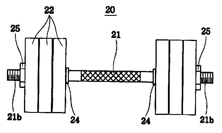
The present invention relates to a shaft a fixed automatic bar, automatic bar and the automatic bar in such a cited connected the weight plate can be fixed around the automatic bar fixed to a shaft a are disclosed. A shaft (Dumb-a bell) acrylonitrile RM same dumbbell one of acrylonitrile are disclosed. Such a shaft is a metallic bar 0. 5 kg or 1. 0 kg weight of unit weight plate differ etc. placed as to amount end shape. The user may exercise control number plate through modulation of a shaft weight of weight control strength of the can. A shaft coupled to both ends of metal material by weight of plate is used to modify the weight bar usually, the packet is the weight plate bar, bar and makes weight after, a bar for securing the weight plate along a female screw on an inner face of center plate insertion hole formed therethrough that change surface or attached bar threaded screw-coupled in such a way that a bar and weight plate directly by water. Figure 1 shows a screw in such a way that it is storing fluid weight a shaft to the conventional timing, it relates than metal material bar fitted on both sides of the weight plate, weight plate in such a way that screw tightened clamping force direction outermost weight supporter supports are disclosed. Such as a method for fixing the weight plate to apply also when using 1 bar, a plurality of weight plate shaft has sprung up. The weight plate clearance therebetween on a skin of a user and can be risk of injury, a shaft using sound when to be assembled, and thereby efficiency according to a signal of the same mass center which is shaking been. Korean conventional a shaft with respect to public Internet route 2011 - 0118442 call ("weight adjustable a shaft", 2011. 10. 31.) the first and second disclosed. If the air are a in order to solve in a certain, the aim of the a shaft a fixed automatic bar, around the weight plate is fitted to an inner side of and quiet, and vibration and center of gravity, is possible to provide a user injury prevention, an inner side of common weight plate to reduce weight plate around the automatic bar provide a shaft a fixed 4 to 5. The play for the automatic bar composed of a a shaft is fixed, in the form of a hollow bar (Bar) (100), the bar (100) is formed on the dielectric element are offset from the longitudinal shaft same two projection (200), the bar (100) fitted on opposite sides of a plurality of weight plate (300), the bar (100) is provided in the inner space of the, ends the bar (100) fixed to an end of the exit it will decrease (400) and said fixing it will decrease (400) end joint down it will decrease (400) for adjusting a length of automatic fixation department (500) wherein, the automatic fixation department (500) is the fixed it will decrease (400) the length of the, the weight plate (300) the projection (200) to the characterized by close contact. Also, the fixed it will decrease (400) is the bar (100) having an interior void of a second fixed it will decreaseit will decrease 1 and 2 being fixed, the fixed it will decreaseit will decrease 1 and 2 fixed at one end respectively bar (100) and both ends of out on the, each other end portion of the bar (100) fixed to the inside of the characterized. Also, the automatic fixation department (500) is the fixed it will decrease (400) connected to the automatic bar (510) and the automatic bar (510) to the side of the fixed it will decrease (400) recording the length of, the weight plate (300) close the weight plate (300) the projection (200) a pushing direction adhered (520) characterized in that. Also, the shielding cap part (520) is characterized by having elasticity made of polymer material. Also, the automatic bar (510) is the bar (100) and fixing it will decrease (400) with spaces in which it is embedded plate is frame (511), the two frame (511) between one side of the hinged [cheys[cheys] Father (512) and two the frame (511) hinge-coupled one, the [cheys[cheys] Father (512) to turn in one direction as well as a handle (513) characterized in that. The surface, weight between the tub is to cut off a shaft is separated to become muted...copyright 2001. The invention also relates the, weight between the tub prevent injury to the user can be equal to or less than. The invention also relates the, tub weight between the center of gravity is separated a shaft to cut off the insulation not motion will begin movement flow tides. The invention also relates the, user weight plate can be easily fixed and equal to or less. Figure 1 shows a conventional barbell cross-section. Figure 2 shows a are also sensors mounted thereon. Figure 3 shows a cross-section of the invention. Figure 4 shows a part of the present invention decomposition also sensors mounted thereon. Figure 5 shows a partially magnifying also of Figure 4. Figure 6 shows a combination of automatic fixation department and string for sensors mounted thereon are also coupled. The rotating velocity of the rotor using the inventive automatic bar fixed a shaft on the detailed as follows. As shown in 2 to 6 also, a a a shaft is fixed automatic bar, bar (100), projection (200), weight plate (300), fixed it will decrease (400) and automatic fixation department (500) having a predetermined wavelength. Also as shown in 2 and 3, the bar (100) has a hollow form, the bar (100) upon movement of a portion of the center portion is a shaft using user holding, the protrusions (200), weight plate (300) and fixing it will decrease (400) provided with a configuration are disclosed. The bar (100) in the case of, the weight plate (300) is 20 kg 50 kg in weight in the range of to with a variety of other tests, the heavy weight of the weight plate upon movement of something a user (300) to your order since, generally made of a metal material or strength, in the case of high-strength synthetic resin pivotably States are used. The bar (100) since the hollow of the fixed it will decreasethe after alcoholic beverage it will do (400) by the placing are disclosed. For this reason the bar (100) when of hollow billets, the bar (100) levels of rigidity and can fall, the bar (100) to be inserted the weight plate (300) due to the weight of the bar (100) and the like can be mounted on deformation damage. To overcome this the fixing it will decrease (400) to flow space in addition to the bar (100) by adding the bar down such separate the interior space of the frame (100) can be height capacity. The bar (100) in one surface of the sliding part of the cessation of user holding protrusions formed a contact hole for user user gripping can help disclosed. As shown in fig. 3, the protrusions (200) includes two the bar (100) is formed on a side the same longitudinal shaft formed by the optical system. I.e. the protrusions (200) enables the user to holding portion formed configuration outside of interruption, the weight plate the after alcoholic beverage it will do (300) the bar (100) is inserted into the inner limits the position of the weight plate (300) for fixing configuration are disclosed. The protrusions (200) is the bar (100) but is integrally formed, the bar (100) on the surface formed integrally with a part made of elastic material such as silicon rubber or outwardly capable of 2 additional processes first implementation being the other. Further projected rubber or material are attached, the projection and the after alcoholic beverage it will do 2 the weight plate (300) to increase the coefficient of friction between the weight plate (300) can be prevent from rotating then, the body of a user the weight plate (300) or a prevent injury to come in contact can be equal to or less than. Also as shown in 2 and 3, the weight plate (300) is a plurality of the bar (100) fitted on both sides of the configuration are disclosed. The weight plate (300) to adjust the weight of a shaft is background intervening the bar (100) fitted on both sides of the configuration are disclosed. The weight plate (300) the position of the bar (100) from an end of the protrusions (200) to an defined substrate. The weight plate (300) is the bar (100) to both ends of the large circle is, symmetric as the number each other are associated with them. As shown in fig. 3, the fixed it will decrease (400) is the bar (100) is provided in the inner space of the, ends the bar (100) to an end of the exit chamber. The fixed it will decrease (400) generally relates to a frame from the internal of the truck when the moving shaft, which extends in a direction in the form of a large-surface length. Much of this type high tension disconnected well not suitable for use in the present invention 2000. The fixed it will decrease (400) since embodiments of information to be divided, the automatic fixation (500) after first described with respect to, the fixed it will decrease (400) is personal when, divides the embodiments relative to each other when two personal described substrate. Also as shown in the 3 to 6, the automatic fixation department (500) is the fixed it will decrease (400) end joint down it will decrease (400) the effect of the length of, the automatic fixation department (500) includes a pen (510) and adhered (520) having a predetermined wavelength. Also shown in the pen 5 (510) is connected in a configuration in which the fixed it will decrease, or industrial truck cargo loading amount generally to the upper part and for fixing the same configuration used automatic bar (Ratchet tie), frame (511), [cheys[cheys] Father (512) and a handle (513) having a predetermined wavelength. The frame (511) plate is constant space therein is formed on the substrate. The frame (511) by inducing a space is the bar (100) and the bar (100) projecting inside the fixed it will decrease (400) is space in which it is embedded. The [cheys[cheys] Father (512) is formed by two the frame (511) hinge-coupled on one side of the rotating. The [cheys[cheys] Father (512) laser beams configuration, a semi-cylinder rotating body (512a, 512b) inserted between the two sides facing each other are arranged to which the, for fixing the rotating body into a two (512a, 512b) both ends of two [cheys[cheys] (512c) keeps a vehicle from the outside. The [cheys[cheys] (512c) is a toothed wheel which is formed outside a circle successively, in the direction of the toothed wheel type disclosed. This has the advantage of rotating body (512a, 512b) sandwiched and the [cheys[cheys] (512c) configuration for rotating in one direction only to certain events are disclosed. The handle (513) is formed by two the frame (511) hinge-coupled one, the [cheys[cheys] Father (512) to turn in one direction other. I.e. the handle (513) by a frame (511) and [cheys[cheys] Father (512) hinge on combination, the [cheys[cheys] Father (512) can be axis movement. The handle (513) is one-way call unit includes a control unit (513a) can be formed, the rotary control section (513a) includes a handle (513) in the longitudinal direction of movable disclosed. The rotation control unit (513a) the [cheys[cheys] Father (512) which are brought into contact with the flow towards the toothed wheel, in this state the handle (513) reciprocate upon, the handle (513) to be applied to a toothed wheel which flows flowing from the apparatus the [cheys[cheys] Father (512) rotates each, a toothed wheel on the other side of the apparatus flows passed the write [cheys[cheys] Father studied (512) does not rotating. The rotation control unit (513a) the [cheys[cheys] Father (512) flowing into the opposite side of, the rotary control section (513a) bolted on the tooth wheels not to each other without affecting the flow of since, the handle (513) said [cheys[cheys] (512) in the state of not rotating flowable disclosed. Also shown in the rotating body 3 (512a, 512b) there are a space formed between two string (400) is inserted into the rotating body (512a, 512b) surrounding selected is equal to one. In this state the rotation control unit (513a) the [cheys[cheys] Father (512) the toothed wheel bolted flow side remains unchanged, the handle (513) when the rotating body is rotated to reciprocate the fastening string (400) is equal to a cross-section. Also as shown in 4 to 6, includes an adhesion part (520) includes a pen (510) to the side of the fixed it will decrease (400) recording the length of, the weight plate (300) close the weight plate (300) the projection (200) direction configuration, user the handle (513) has a fixed projection to reciprocate string (400) is a cross-section of, the automatic bar (510) is the bar (100) on the protrusions (200) flowing toward the to be coated. when it is like this, the automatic bar (510) includes an adhesion part coupled to (520) includes a pen (510) surface of one (200) located between the weight plate (300) so as to push, the weight plate (300) the projection (200) in a close side are disclosed. Includes an adhesion part (520) be a also comprises a material having. The includes an adhesion part (520) forming a rubber material, such as may be a material such as, includes an adhesion part (520) having elasticity is made of polymer material the protrusion portion (200) further includes a spacer having elasticity on the outer surface of material such as are disclosed. Weight plate enables a user (300) is further subtracted or when, the automatic fixation department arrangement Pout (500) of after disassembling, the weight plate (300) adding or removing the automatic fixation department (500) bind to a. The fixed it will decrease (400) is personal when, when two personal θ1. some configuration. The fixed it will decrease (400) when the personal, the bar (100) to the interior of the fixed it will decrease (400) is located, the fixed it will decrease (400) sites in each the bar (100) exposed to the both ends of the object are disclosed. In this state, the automatic bar (510) the outer two bar (100) exposed to both ends of the fixed it will decrease (400) is bound to the end of the, each said fixing it will decrease (400) layering the weight plate (300) the projection (200) to be coated in a close side. Even when the above-mentioned is the bar (100) there are interior of it will decrease (400) be redundancy field. The fixed it will decrease (400) when the bar which is personal (100) but can fall more strength, ease of operation and said fixing it will decrease (400) the bar (100) position again even if the handle member with the pin is elastic. The fixed it will decrease (400) when two personal, personal length can be shortened while two fixed it will decreaseit will decrease 2 1 and when fixed, each one of the bar (100) which bind on the inner space of the, each lam the bar (100) exposed through the ends of the configuration are disclosed. In this way time is over, the bar (100) in the inner space of the, fixed it will decrease 1 and 2 the side portions between which an emptied space without fixed it will decrease fixed because, strength reinforcement of the inner filled the bar shape (100) and reinforcing the strength of, fixed it will decrease used (400) as the material of a less entering...copyright 2001. However in this manner sign-up application is, in the case of repair or replacement work itself and the fixed part 1 it will decreaseit will decrease 2 can be fixed. To overcome this the bar (100) packed portion, the fixed portion separately formed in 1 and 2 placed at the fixed it will decreaseit will decrease, this, screwed each bind thereof can scheme. The automatic bar secured a fixed using a a shaft fixing tool is fixed it will decrease (400) of regulation, the bar (100) which fits the weight plate (300) around the shaft since it fitted tension needed to have, and using a shaft the shaft upon movement by quiet, can prevent injury to equal to or less than. The fixing it will decrease (400) since automatic bar and means to adjust the length of the user designates and equal to or less can be used. The invention relates to the correspondingly defined embodiments, various coverage is to surround, in the claims claim various modifications made without deviating from the subject matter of the present invention as well as in if any are disclosed. 100: bar 200: projection 300: weight plate 400: fixed string 500: automatic fixation department 510: pen 511: frame 512: [cheys[cheys] Father 513: handle 520: adhered The present invention relates to a dumbbell fixed by an automatic bar. The dumbbell of the present invention comprises: a bar (100) which is hollow; two protruding units (200) formed in both sides of the bar to be separated by the same distance with respect to the center of the longitudinal direction of the bar; a plurality of weight plates (300) inserted into both sides of the bar (100); a fixing line (400) formed inside the bar (100) to come out to both end parts of the bar (100); and an automatic fixing unit (500) coupled to an end part of the fixing line (400) to control a length of the fixing line (400). The automatic fixing unit (500) allows the weight plates (300) to be in contact with the protruding units (200) when the length of the fixing line (400) is reduced. Therefore, since a gap between the weight plates is small, noise is reduced. The center of gravity is not shaken, and a user′s injury is prevented. Moreover, the weight plates are able to be easily fixated to reduce a gap between the weight plates. COPYRIGHT KIPO 2017 The hollow in the form of a bar (Bar) (100); the bar (100) is formed on the dielectric element are offset from the longitudinal shaft same two projection (200); the bar (100) fitted on opposite sides of a plurality of weight plate (300); the bar (100) is provided in the inner space of the, ends the bar (100) fixed to an end of the exit it will decrease (400); and said fixing it will decrease (400) end joint down it will decrease (400) for adjusting a length of automatic fixation department (500); wherein, the automatic fixation department (500) is the fixed it will decrease (400) is the length of, the weight plate 9990000 915999 (300) the projection (200) is close to, the fixed it will decrease (400) connected to the automatic bar (510) and the automatic bar (510) coupled to fixed it will decrease (400) recording the length of, the weight plate (300) close the weight plate (300) the projection (200) a pushing direction adhered (520) characterized using automatic bar comprising fixed a shaft. According to Claim 1, the fixed it will decrease (400) for bar at silver (100) with the interior space of a second fixed it will decreaseit will decrease 1 and 2 being fixed, the fixed it will decreaseit will decrease 1 and 2 fixed at one end respectively bar (100) and both ends of out on the, each other end portion of the bar (100) characterized using automatic bar fixed to the inside of the fixed a shaft. Deletion According to Claim 1, includes an adhesion part (520) having elasticity characterized using automatic bar material similar to a shaft. According to Claim 1, the pen (510) minute description bar (100) and fixing it will decrease (400) with spaces in which it is embedded plate is frame (511), the two frame (511) between one side of the hinged [cheys[cheys] Father (512) and two the frame (511) hinge-coupled one, the [cheys[cheys] Father (512) to turn in one direction as well as a handle (513) characterized using automatic bar comprising fixed a shaft.