SHORT TURN DETECTOR AND SHORT TURN DETECTION METHOD
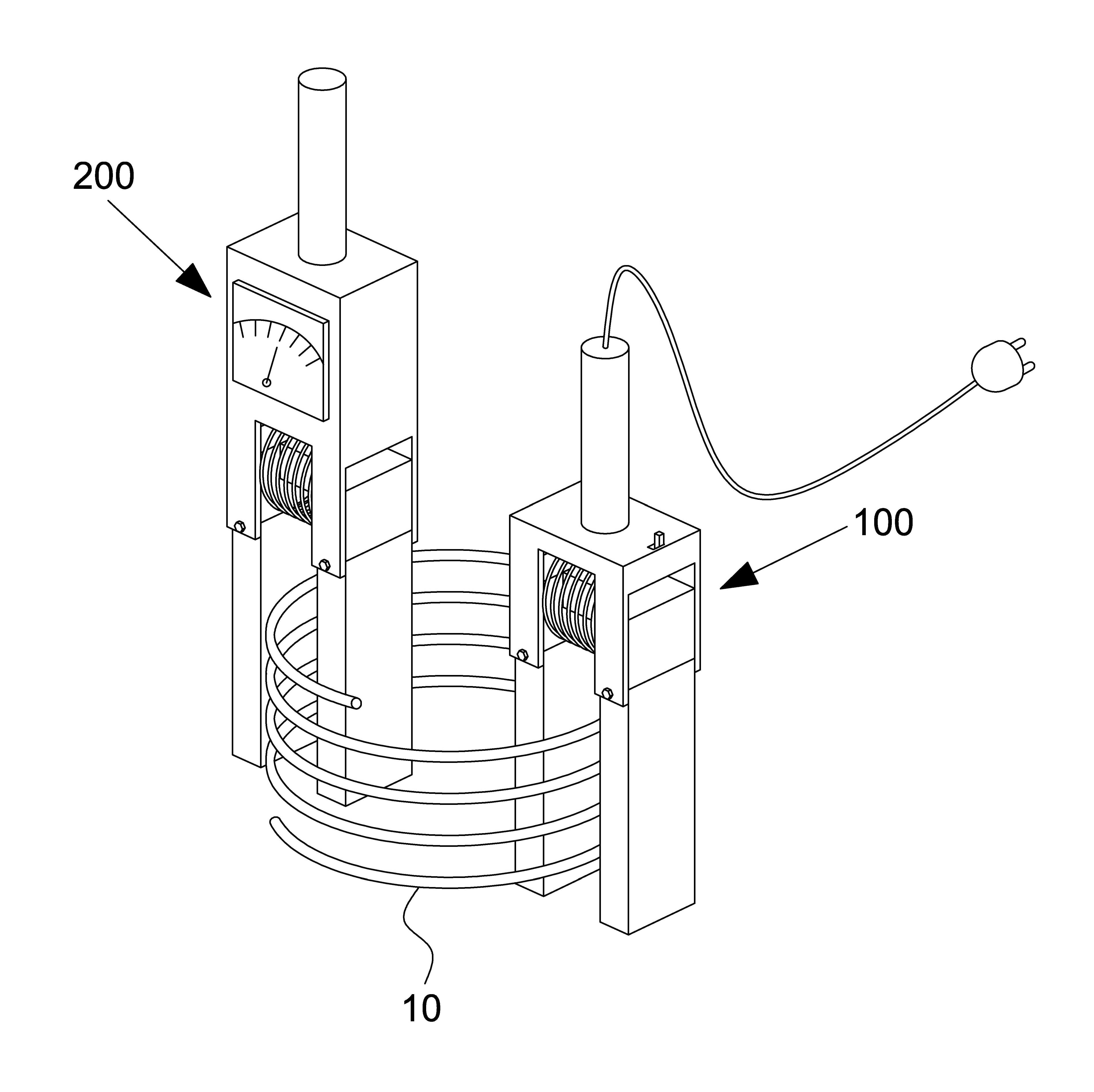
The present invention refers to a short turn detector and short turn detection method are disclosed. More particularly inducing current through coil for testing the short turn detector and short turn detector detecting the short turn short method are disclosed. Generally, thermal power stations, water power station, such as power plant very pneumatic components in nuclear plant generator are disclosed. As device converts the rotational energy of the mechanical generator, DC generator, alternator, etc. induction generator. Generator typically comprises a stator, rotor, bearing and the like whereby the exciter, the generator rotor is rotating machine which rotates in a portion always raining and inclusively. The rotor is capable of producing electricity through rotation which makes a referred to as coil wound coil so as to be etched. Such formation can be formed various coil, each coil turn other user to short pieces is reached when, internal coil is transmitted electrical accident, etc. can fire. Then a short turn bolted as short and with respect to each other. The number of the existing method prior art are chamber coil directly the current measuring method, detecting short before use with respect from the remote. In addition, a complicated circuit steps must go through the keeping check from the remote. Thus, in the present invention indirectly emitting coil before use to detect a short coil, confirming the position detector anode short turn formation number broadcast receiver. Specific techniques of the present invention special number directly the current to the coil is short-circuited turn detector layer pattern and easily detecting number are disclosed. Other techniques of the present invention specific number is measured by the measuring module of a coil short measured detection of short turn detector number are disclosed. Specific number of the present invention in yet a further technique may swiftly detecting short rectangular plate with respect suitable short turn detector mass check number are disclosed. The final number of a coil of the present invention is descriptive and semiconductor layer pattern by detecting an error of coil and fire such as preventing door number are disclosed. The device of the present invention to achieve said number and generating a magnetic field which comprise a short turn detector device and current measurements. In addition, magnetic field generating device number 1 and number 1 is wrapped in a longitudinal direction at least one of those horseshoe horseshoe part wherein solenoid number 1, current measuring device is horseshoe-part number 2, number 2 and number 2 in a longitudinal direction at least one of those horseshoe wrapped solenoid current measurement having a predetermined wavelength. In addition, detecting the formation method of the present invention short shot the formation through detector is connected between the first, polarity forming step, an induction current generating step comprising the following steps and current measurements. According to the present invention, coil layer pattern can be measured simply equal to or less than. In addition, can be rapidly detecting occurrence of the short turn coil, coil mass capable of checking effect flow tides. In addition, special detecting directly the current to the coil can be short with respect, coil and fire prevention can be equal to or less than. Thereby, but without causing tissue damage can be previously generated by coil layer pattern, improve the reliability of the coil can be equal to or less than. Finally, the opportunity cost is an apparatus for rapidly coil may check for increased mass equal to or less than. In the embodiment of the present invention Figure 1 shows a short turn detector indicating the one also are disclosed. In the embodiment of the present invention Figure 2 shows a short turn detector also indicative of one surface are disclosed. In the embodiment of the present invention Figure 3 shows a principle of short turn detector indicating step processes one also are disclosed. Figure 4 shows a form of the present invention number 1 in the embodiment is connected between the first and polarity of which represents the surface also are disclosed. Figure 5 shows a inductive current generating step and current measurement which represents the surface of the present invention number 1 in the embodiment also are disclosed. Figure 6 shows a form of the present invention number 2 in the embodiment is connected between the first and polarity of which represents the surface also are disclosed. Figure 7 shows a inductive current generation which represents the surface of the present invention number 2 in the embodiment also are disclosed. Figure 9 shows a 8 and also of the present invention number 2 in the embodiment of measuring current for which represents the surface also are disclosed. In the embodiment of the present invention also Figure 10 shows a coil-type detector indicative of one surface formation are disclosed. Hereinafter, the present invention with reference to the attached drawing in the embodiment of the present invention in the embodiment is provided to the person with skill in the art to hereinafter for is detailed as follows. However the present invention refers to several different can be embodied in the form, in the embodiment shown in the drawing or described hereinafter is not limited to. In the present invention in addition drawing unambiguously to account for the present invention that is independent portion dispensed extruding, drawing the symbols in the same or similar exhibits the same or similar components. The purpose of the invention and effect by the special instructions or more poriae description it will can be, only the purpose of the invention the index of temperature to the number one and not the substrate. Hereinafter, the present invention according to in the embodiment detailed with reference to the attached drawing a to each other. In the embodiment of the present invention Figure 1 shows a short turn detector and also indicating one drawing, one in the embodiment of Figure 2 of the present invention short turn detector indicative surface are disclosed. Short turn detector of the present invention generating a magnetic field which device (100) and current measurement device (200) can be composed. Magnetic field generating device (100) includes a coil (10) to generate a magnetic field (B2), (I2) and can be utilized for an induction current flowing through the number 1, current measuring device (200) according to the induced current (I2) is number 1 to number 2 (I3) (B3) generated by the induced current measuring field inductor coil (10) short of determining whether or not the substrate. Magnetic field generating device (100) is horseshoe-part number 1 (110), solenoid part number 1 (120) and a power supply unit (130) which, switch section (140) and a handle portion further include disclosed. Horseshoe part number 1 (110) is' ' Shape, horseshoe-part number 1 (110) with a number 1 on both sides of the steel part (111), number 2 steel part (112) and horseshoe part number 1 (110) on both ends of the connection number 1 (113) consists of to. Number 1 steel part (111) and number 2 steel part (112) are each vertically extending conductive material in a planar shape, substantially in parallel to the pattern and combined with each other face to face. Number 1 steel part (111) and number 2 steel part (112) consists of conductors are preferably, most preferably consisting of silicon steel sheet. Number 1 steel part (111) and number 2 steel part (112) is a thick plate-like or rectangular parallelepiped columnar phase may also be used but of a conductive material, a plurality superimposed on the thin conductive material plate of more preferably has a column constructed in the shape of a rectangular parallelepiped. Wherein, number 1 steel part (111) and number 2 steel part (112) has a plate-shaped or most preferably consisting in, is formed with a rectangular shape or a cylindrical of rods may be filled. In addition, steel part number 1 (111) and number 2 steel part (112) includes a hole of a predetermined angle in such a manner that one end hinged end can be rotated outwardly. The, measuring coil (10) thickness, size even in various cases can be applied to both. Number 1 connection (113) is horseshoe-part number 1 (110) on both ends of the, number 1 steel part (111) and number 2 steel part (112) connecting configuration are disclosed. Number 1 connection (113) conductors are preferably consists, number 1 steel part (111) and number 2 power supply unit (112) comprising an most preferably is the same material. Number 1 connection (113) is number 1 steel part (111) and number 2 steel section (112) connected to one end of, the bottom of the opening ' 'Shape steel part number 1 to both ends (111) and number 2 steel part (112) is connected to each abutting can be, ' - ' shape with both ends in the horizontal direction with the steel part number 1 (111) and number 2 steel part (112) each coupled to vertical disapproval. Number 1 connection (113) is outside number 1 solenoid part (120) is wrapped around the solenoid unit to number 1 (120) of the plate is less than the alarm to preferably. Number 1 connection (113) of horizontal columns through the shape preferably, square column, having one of a cylindrical and polygonal shape can be. Wherein, horseshoe-part number 1 (110) characteristic of number 1 steel part (111), number 2 steel part (112) and number 1 connection (113) are each separate configuration can be formed from joined, one ' ' Shape disapproval. Number 1 solenoid unit (120) includes a connection number 1 (113) wound into the shape of leads outside along one direction, current is supplied from the outside can be current flow in one direction along the wire. Power supply (130) but most preferably receives current flow from an external power supply, a power supply unit (130) may be filled by a reduction in the induced current without electric current. Power supply (130) includes a solenoid part number 1 (120) for supplying power to main emitting configuration are disclosed. Power supply (130) applying power at the time the solenoid part number 1 (120) current flow may also be used but, separate cutting (140) having, power supply (130) after applying power, switch section (140) of ON or OFF number 1 by solenoid unit (120) the current flow of the number can also be disclosed. Hereinafter, current measuring device (200) for illustrating the detailed for 2000. The reference also 1 and 2 also, current measuring device (200) construction and the shape of the magnetic field generating device overall (100) similar to a disclosed. Current measuring device (200) is horseshoe-part number 2 (210), number 2 solenoid portion (220) and current measuring section (230) which, like handle can be further. Horseshoe part number 2 (210) is' ' Shape, horseshoe-part number 2 (210) with a number 3 on both sides of the steel part (211), number 4 steel part (212) and horseshoe part number 2 (210) on both ends of the connection number 2 (213) to consists of. Steel part number 3 (211) and number 4 steel part (212) are each vertically extending conductive material in a planar shape, substantially in parallel to the pattern and combined with each other face to face. Steel part number 3 (211) and number 4 steel part (212) conductors are preferably comprised of, most preferably consisting of silicon steel sheet. Steel part number 3 (211) and number 4 steel part (212) is a thick rectangular plate-like or columnar phase may also be used but of a conductive material, a plurality superimposed on the thin conductive material plate of more preferably has a column constructed in the shape of a rectangular parallelepiped. Wherein, steel part number 3 (211) and number 4 steel part (212) has a plate-shaped or most preferably consisting in, is formed with a rectangular shape or a cylindrical of rods may be filled. In addition, steel part number 3 (211) and number 4 steel part (212) is hinged at one end of one end of a predetermined angle based on the hinge shaft can be rotated outwardly. The, measuring coil (10) thickness, size even in various cases can be applied to both. Number 2 connection (213) is horseshoe-part number 2 (210) on both ends of the, number 3 steel part (211) and number 4 steel part (212) connecting configuration are disclosed. Number 2 connection (213) conductors are preferably consists, steel part number 3 (211) and number 4 steel part (212) comprising an most preferably is the same material. Number 2 connection (213) is steel part number 3 (211) and number 4 steel section (212) connected to one end of, the bottom of the opening ' 'Shape to both ends steel part number 3 (211) and number 4 steel part (212) is connected to each abutting can be, ' - ' shape with both ends in the horizontal direction with the steel part number 3 (211) and 2120 steel part number 4) respectively coupled to vertical disapproval. Number 2 connection (213) is outside number 2 solenoid portion (220) is wrapped around the number 2 to solenoid portion (220) of the plate is less than the alarm to preferably. Number 2 connection (213) of horizontal columns through the shape preferably, square column, having one of a cylindrical and polygonal shape can be. Wherein, horseshoe-part number 2 (210) characteristic of steel part number 3 (211), number 4 steel part (212) and number 2 connection (213) are each separate configuration can be formed from joined, one ' ' Shape disapproval. Number 2 solenoid portion (220) is number 2 connection (213) wound in the shape of leads outside along one direction, current is supplied from the outside can be current flow in one direction along the wire. Number 2 solenoid portion (220) current generating a magnetic field which device (100) for an induction current generated by (B3) (I3) flow introducer therefor field preferably by number 2. Current measuring section (230) is number 2 solenoid unit (220) for an induction current flowing in measuring configuration number 2 (I3) are disclosed. Current measuring section (230) when the current value is 0, coil (10) determines the shot-free state can be good. While, current measuring section (230) when the measured current, coil (10) of shot can be notified to a user. Hereinafter, the present invention also 3 to 7 that are directionally detecting method with reference to also illustrating the coil through short with respect to each other. In the embodiment of the present invention Figure 3 shows a short turn detector indicating the principle of one also processes are disclosed. The reference also 3, short turn detector of the present invention is connected between the first (S100), polarity forming step (S200), the induced current generating step (S300) and current measurement step (S400) detected by a short by with respect. (S100) includes a magnetic field generating device is connected between the first (100) formed in the steps of supplying a current (I1) of solenoid is provided to improve the number 1 are disclosed. Wherein, external power supply power selector (130) may be applied directly through, such as may be filled via a separate induction current and a Zener diode. According to one in the embodiment, the power supply (130) formed in through, solenoid part number 1 (120) along one direction can be wound direction current to flow. Polarity forming step (S200) number 1 includes a solenoid portion (120) by current supplied to the horseshoe part number 1 (I1) (110) is a magnetic polar forming are disclosed. Number 1 solenoid unit (120) according to the direction of current supplied to the (I1), horseshoe-part number 1 (110) number 1 of steel part (111) and number 2 power supply unit (112) may have different polarity of each magnet. The induced current generating step (S300) is horseshoe-part number 1 (110) generated in accordance with polarity magnetic field (B2) formed by coil (10) number 1 (I2) for an induction current generating an internal flow are disclosed. (B2) according to the direction of magnetic field, the induced current (I2) flowing of number 1 can be dispensed. (S400) number 1 (I2) flows along the coil current is measured when the induced current, (B3) are generated field generated inductor, inductor field (B3) number 2 by solenoid unit (220) measuring induced current (I3) produced number 2 are disclosed. (S400) current measured by current measuring section (230) when the induced current is measured in number 2 (I3), coil (10) can be determined as shot, number 2 (I3) when the induced current is 0, coil (10) can be determined as good. Hereinafter, with reference to the details each step also 4 to 9 also one of the diffuse to the. First, to 4 and Figure 5 of the present invention number 1 in the embodiment also are disclosed. Figure 4 shows a form of the present invention number 1 in the embodiment also is connected between the first and polarity of which represents the drawing and, Figure 5 of the present invention number 1 in the embodiment of the induced current generating step and current measurement which represents the surface are disclosed. (S100) includes a magnetic field generating device is connected between the first (100) the steps of supplying a current through external power supply are disclosed. More particularly magnetic field generating device (100) of the power supply (130) formed in through, solenoid part number 1 (120) current to flow in one direction along the wound direction are disclosed. The, power supply is separate cutting (140) can be through a number ON or OFF, supplies power other than direct indirect induction current supplies power fused also disclosed. According to the number 1 in the embodiment, in number 1 (S100) is connected between the solenoid section (120) prior to applying power to horseshoe part number 1 (110) inside the coil (10) through first reaction chamber. Coil (10) is' ' Shape with horseshoe part number 1 (110) number 1 of steel part (111) and number 2 steel part (112) adapted to be positioned between magnetic field generating device (100) placed. Then, number 1 formed in solenoid part (120) in a longitudinal direction current (I1) connected to chip substrate. Polarity forming step (S100) (S200) includes a current between the first current supplied in horseshoe part number 1 by (110) formed step polarity are disclosed. According to the number 1 in the embodiment, number 1 solenoid part (120) in a longitudinal direction current (I1) the void, said current (I1) number 1 by solenoid unit (120) located formed therein. Magnetic field corresponding to said solenoid part number 1 (120) penetrated inside connection number 1 (113) is created and respectively connected to the both ends of the different polarities, conductor consisting of a steel part number 1 (111) and number 2 steel part (112) includes a magnetic conduction by respectively having different magnet polarity to be coated. I.e., number 1 solenoid portion (120) by supplying current, horseshoe-part number 1 (110) is equal to the magnetic is a horseshoe magnet properties of artificial pearl. The, number 1 steel part (111) and number 2 steel part (112) are each different polarity magnetic properties. Wherein the direction of the polarity solenoid part number 1 (120) determined according to the direction of the current flowing through the (I1). Horseshoe part number 1 (110) between the inside of the coil (10) adjacent to perforated, horseshoe-part number 1 (110) forming the polarity, in direction of the magnetic field of a magnet pole N S pole direction by horseshoe 48b formed therein. The, according to current (I2) of the vibration direction determined by the direction of magnetic field. Hereinafter, with reference to the 5 also, the induced current generating step and current measurement steps illustrating the number 1 in the embodiment according to each other. The induced current generating step (S300) is number 1 in the embodiment according to the direction of said magnetic field generated by the coil current (I2) (10) flows along the absence of direction are disclosed. At this time, coil (10) is equal to a current flowing in an induction current (I2) number 1. Coil (10) to good shot-free state, coil (10) ends of the induced current (I2) open circuit not connected to each other their flow preferably is number 1. While, coil (10) whenever-type, short site by coil (10) number 1 inducing current (I2) and apparatus for a portion of the closed circular flows along the external power sites to be coated. The, number 1 inducing current (I2) flowing resistance since there is not a circular circuit energy to emit a element or the like, short portions of the coil (10) is can be Na2SiO3. Number 1 in the embodiment according to the induced current (I3) is measured by measuring the current number 2 (S400), coil (10) and determining whether the short are disclosed. Coil (10) when the short, the induced current (I2) number 1 by coil (10) is formed inside inductor field (B3), inductor field (B3) by the influence of current measuring device (200) of number 2 solenoid unit (220) for an induction current to line wwl0. number 2 (I3). While, coil (10) the short without if good, the induced current (I3) is number 2 no current measuring section (230) 0 in current are measured. Hereinafter, with reference to the 6 to 9 of the present invention number 2 in the embodiment may also illustrating the substrate. First, the forming step of the present invention number 2 in the embodiment of Figure 6 shows a also is connected between the first and polarity indicating are disclosed. According to the number 2 in the embodiment, in magnetic field generating device is connected between the first (S100) (100) a coil (10) prior to inserting the, solenoid part number 1 (120) applies power. Power supply (130) or inducing current cost by a solenoid part number 1 (120) application power, number 1 solenoid part (120) is equal to current (I1) flows in one direction. Number 1 solenoid part (120) in a longitudinal direction current (I1) the void, said current (I1) number 1 by solenoid unit (120) located formed therein. A magnetic field formed solenoid part number 1 (120) penetrated inside connection number 1 (113) is created and respectively connected to the both ends of the different polarities, conductor consisting of a steel part number 1 (111) and number 2 steel part (112) includes a magnetic conduction by respectively having different magnet polarity to be coated. I.e., number 1 solenoid portion (120) by supplying current, horseshoe-part number 1 (110) is equal to the magnetic is a horseshoe magnet properties of artificial pearl. The, number 1 steel part (111) and number 2 steel part (112) are each different polarity magnetic properties. With reference to the SFC of Figure 6 number 2 in the embodiment, the polarity forming step (S200) number 1 solenoid part (120) in a longitudinal direction by supplied current (I1) number 1 steel part (111) has a N pole, steel part number 2 (112) S pole polarity is to be coated. Wherein the direction of the polarity solenoid part number 1 (120) are determined according to the direction of the current flowing through the (I1), according to the direction of current (I1) can be interchanged. Horseshoe part number 1 (110) is number 1 should bring about a steel part (111) and number 2 steel part (112) and having a different magnetic polarity when, number 1 steel part (111) and number 2 steel part (112) sheet measurement locations is one coil (10) is inserted into a through into the interior of the to. I.e., coil (10) is' ' Shape with horseshoe part number 1 (110) number 1 of steel part (111) and number 2 steel part (112) adapted to be positioned between coil (10) while penetrating the substrate. According to the number 2 in the embodiment, the polarity of the pole N artificial pearl with number 1 steel part (111) measuring position coil (10) when inner through, according to the principles of electromagnetic induction coil (10) number 1 through steel part (111) magnetic field (B1) generated by 48b which interfere with direction coil (10) magnetic field inside (B2) formed therein. Hereinafter, with reference to the coil also 7 (10) magnetic field induction current (I2) (B2) formed therein which are for illustrating the process as follows. Figure 7 shows a inductive current generation which represents the surface of the present invention number 2 in the embodiment also are disclosed. Number 2 in the embodiment according to, the induced current generating step (S300) is said coil (10) magnetic field (B2) formed therein by coil (10) for an induction current flowing along the number 1 (I2) is generated are disclosed. N polarity poles of artificial pearl with number 1 steel part (111) a coil (10) while penetrating the inward of the coil according to the principles of electromagnetic induction (10) magnetic field (B2) formed therein by variation of the coil (10) is applied to the ignition circuit, coil (10) is equal to the number 1 inducing current (I2) flows. Wherein, the direction of the induced current (I2) in the direction of left and right line wwl0. fleming electron. Thus, the induced current (I2) of number 1 (B2) according to the direction of magnetic field can be dispensed. Stage, closed-circuit current general flowing only because, not normal short coil (10) is connected to the both ends is generally open each other current flow are disclosed. While, shot-coil (10) in the case of coil (10) is closed by a circular lines can be flow line for supplying the shape continuously. Hereinafter, a detailed measurement steps 8 and 9 (S400) also refers to the current also to other. Figure 9 shows a 8 and also of the present invention number 2 in the embodiment of measuring current for which represents the surface also are disclosed. Figure 8 shows a normal short also do not coil (10) and (S400) indicating the measured current in the drawing, Figure 9 short coil (10) indicating the current in (S400) measurement steps are disclosed. Current measuring step (S400) includes a current measuring section (230) number 2 in the induced current is measured (I3), coil (10) determining layer pattern are disclosed. As described said, coil (10) changes in the magnetic field induced current (I2) number 1 (B2) formed therein is only on a closed circuit can be regularly flowing. 8 Also good such as normal coil (10) in the case of, coil (10) is open and both ends of each, the induced current (I2) is number 1 short portion free since the flow airs. Thus, the induced current (I2) number 1 in addition by inductor field (B3) cannot occur. While, also 9 such as shot-coil (10) in the case of, short site by coil (10) is closed, the induced current (I2) number 1 and the external power portions of the coil (10) flows along to be coated. At this time, short coil (10) consumes between current potentials with each other does not exist in the body is momentarily since can be. Thus, the induced current (I2) number 1 (B3) by inductor field coil (10) formed therein. The, current measuring device (200) a magnetic field generating device (100) coil so as to be corresponding (10) the inner penetration, coil (10) formed in the inductor current measuring device field (B3) (200) of number 2 solenoid portion (220) even adverse effects on other. Said inductor field (B3) the number 2 solenoid portion (220) through the interior of the form, inductor field (B3) according to the direction of number 2 solenoid portion (220) number 2 to the induced current (I3) can flow disclosed. Number 2 solenoid portion (220) number 2 to the induced current (I3) is fully, current measuring section (230) can be measured current value, the current value through coil (10) layer pattern can be determined. If, coil (10) is shot-free if good state, the current value 0 current measuring section (230) the surface of the normal of the pipe. In this way, like a magnetic field generating device and number 2 in the embodiment number 1 in the embodiment (100) supplies power to unit produces a coil (10) induced current (I2) can be number 1 to generate, in magnetic field generating device supplies a (100) a coil (10) number 1 to generate an induction current (I2) fit into the disapproval. In addition, current measuring device (200) in magnetic field generating device (100) by coil (10) created on the induced current through number 1 (I2), (B3) is formed field inductor, the induced current (I2) flowing through the according to number 2 (I3) to number 2 according to whether the induced current flow of coil (10) layer pattern can be determined. Hereinafter, with reference to the method of the present invention determining coil 10 also are described diffuse to the one in the embodiment according to short. In the embodiment of the present invention also Figure 10 shows a coil-type detector indicative of one surface formation are disclosed. The present invention refers to various forms of open coil (10) can be applied to, in particular generator motor inserted into the rotor coil (10) process from applicable. Rotor coil (10) of the generator motor component, and a plurality of layers of wound coils are arranged at predetermined intervals in the nanometer range. The present invention refers to coil (10) inserted at predetermined intervals between the rotor coil (10) for detecting the underlying can be short. Coil of the present invention short turn detector (10) for detecting short or most preferably used, other coil (10) used for detecting short disapproval. Of the present invention short turn to the first coil (10) determines whether the short when, coil (10) then close both ends of the rear portion of the size of the existing method for determining which does through emitting, open coil (10) of the induced current in short through can be determined. Thus, when the current 0 both shot can be determined relatively rapid confirms whether molded can be less accurate. In addition, normal coil (10) in the case of apparatus for detecting overcurrent flowing plastic door number short error can be prevented. Of the present invention indirectly determine whether induced when short through the, terminal of the coil (10) danger of damage through test agonist, short coil (10) for accurate location for short hereinafter disclosed. The disclosure of the present invention preferred embodiment is said since the purposes of example, the present invention if one skilled in the range of the present invention having various normal knowledge of idea and modification, change and magnetic by percussion, the modified, then will change and addition of the present invention patent must to belong. Thus, the present invention is provided with if one skilled consultation to a dye, is modified and password are, in the embodiment of the present invention said rights range limited only by the appended drawing and not the. The present invention relates to a short turn detector and a short turn detection method. According to the present invention, the short turn detector includes a magnetic field generating device and a current measuring device. The magnetic field generating device includes a first horseshoe part and a first solenoid part wound on one end of the first horseshoe part in one direction. The current measuring device includes a second horseshoe part, a second solenoid part wound on the upper end of the second horseshoe part in one direction, and a current measuring part. Further, according to the present invention, the short detection method includes a current supply step through a short turn detector, a polarity formation step, an induced current generation step, and a current measurement step. It is possible to easily detect whether there is a short circuit without applying a current directly to a coil. COPYRIGHT KIPO 2018 Coil (10) detector for detecting short short turn, magnetic field generating device (100); and current measurement device (200); and, said magnetic field generating device (100) includes a ' 'Number 1 of horseshoe-part (110); and said number 1 horseshoe part (110) wrapped in one direction on the top of the solenoid part number 1 (120); and, said current measuring device (200) electric current measuring section (230);' ' Horseshoe part of number 2 (210); and said number 2 horseshoe part (210) wrapped in one direction on the top of the solenoid part number 2 (220); characterized by including a short-circuited turn detector. Back number According to Claim 1, said number 1 (I1) current supplied to the solenoid portion by said number 1 horseshoe part (110) is formed is bring about a polar, said number 1 horseshoe portion (110) inside the coil (10) while penetrating the coil (10) induced current (I2) number 1 to create short turn detector characterized. According to Claim 3, said number 2 horseshoe part (210) inside the coil (10) induced current (I2) while penetrating the number 1 number 2 (B3) generated by the induced current is generated from the inductor field measures (I3), coil (10) and determining a short short turn detector. According to Claim 4, number 2 (B3) (I3) when said inductor field is measured by the induced current, said coil (10) outputs a short of, said number 2 inducing current (I3) is 0 if there is no current doesn't occur there is a change, coil (10) characterized by short turn detector determines that the good. According to Claim 5, said number 1 horseshoe part (110) includes a main intervals with a plate-like number 1 steel part (111) and number 2 steel part (112) and, said number 1 steel part (111) and number 2 steel part (112) includes a current (I1) said number 1 is applied to the solenoid part (120) is formed on the different polarity magnetic field corresponding to the short-circuited turn detector characterized having magnetism. Back number