DRIVING WHEEL BEARING AND METHOD FOR MANUFACTURING SAME
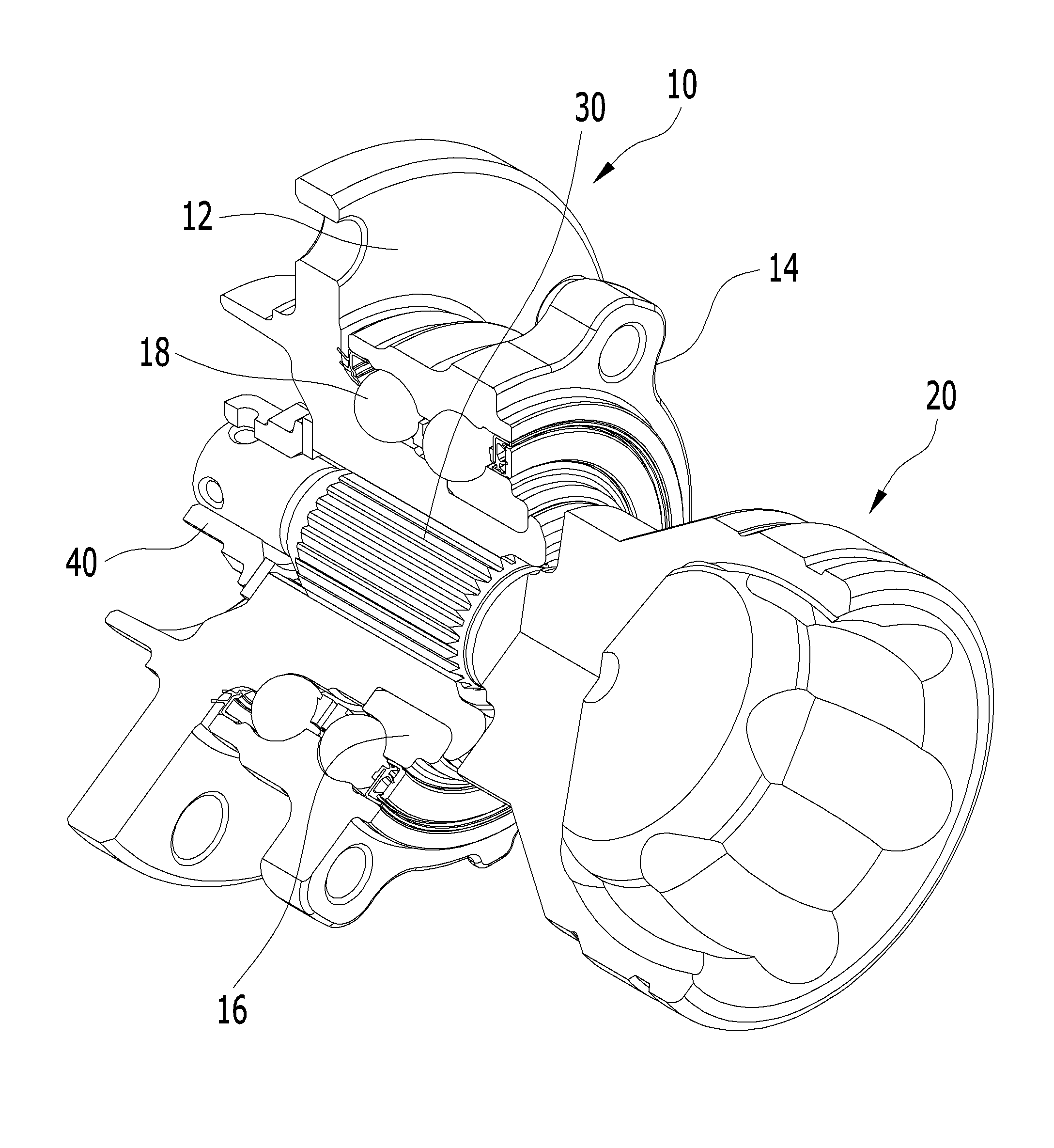
Relates to bearing drive wheel the present invention refers to, more specifically an outer or wheel hub for wheel bearing and constant velocity joint face spline coupled to a drive wheel display method and apparatus of manufacturing method relates to. Is possible to vehicle generally the wheel bearing, capable of wheel without causing and unnecessary friction loss is rotate supplier body lower face is. serves for the mounting of spinning of a wheel to the. The vehicle engine driving force to the wheels delivering device drive train of an automobile ;. generally comprising random joint. Loss of speed during constant velocity joint of a vehicle said vehicle is bounded or diameter from wheel upon separation structure of press die or displacement while provided to absorb the axial displacement or moments engine to the wheels make unit smoothly. Recently save resource for reducing discharge, and pollutant discharge improve the fuel-air ratio of the vehicle is is required, in order to meet such needs drive train of an automobile; with weight in sufficiently endure the information on the connection component and the device for the improved wheel supports rotation of the rotation a wheel bearing constant velocity joint a search for power transmission structure is proposed of wet liquid to flow down. Also the 1 clutch system such as a constant velocity joint in the bearing to correct an outline depending on which is rotatable integrally with a rope is securely joined to a drive wheel bearing of is shown one example. Wheel bearing (10) constant velocity joint in the (20) through which the be inserted, spline (30) of at least one or more wheel bearing (10) a constant velocity joint (20) is rotated integrally with the. is rotatably coupled. Said wheel bearing (10) and a metal line position the not shown rotated integrally with the releasably fasten a wheel hub (12) and a, said wheel hub (12) positioned radially outside the wheel hub (12) is rotatably supported to prevent the inflow of body knuckle such as an outer ring supported secured to a fixed body (14), said wheel hub (12) outer peripheral surface of which is rotatable integrally with a rope fits is mounted has an inner ring (16) and, said wheel hub (12) and the outer race (14) and between said inner ring (16), an outer wheel (14) is interposed between the said wheel hub 88800000 68888 (12) and a inner ring (16) is said outer ring (14) a frame is able to be rotated relative to rolling (18) includes. Said constant velocity joint (20) the said wheel hub (12) passed through the peripheral the wheel hub (12) on the inner circumferential surface thereof at spline (30) which is rotatable integrally with a rope of at least one or more said by refrigerant delivered from the lower stage is securely joined to the wheel hub (12) and a constant velocity joint (20) axial direction of to prevent separation seperation and (40) is said constant velocity joint (20) is secured to a tip outer axial direction of. Said spline (30) the said wheel hub (12) is inserted into a mounting hole mounted said constant velocity joint (20) surface of axis of, alternately and continuously formed having a toothed and groove , in addition said wheel hub (12) in said constant velocity joint (20) axis of the inner peripheral surface is sandwiched site, alternately and continuously groove and a tooth formed is provided with a. the constant velocity joint (20) said tooth form of the wheel hub (12) is assembled by inserting it over the in groove of, said wheel hub (12) tooth form of constant velocity joint (20) is inserted in groove fixing device is installed at the side of, said wheel hub (12) and a constant velocity joint (20) has a toothed and which is rotatable integrally with a rope groove coupled the direction of the periphery is has such a structure that is securely joined to. Said constant velocity joint is of the casing and rotatably supports the copyright (20) through the wheel bearing (10) wheel hub for (12) is, and delivered to the wheel via. Said state of the SP heads and of the existing method such as in a composite structure is an end and coupled a constant velocity wheel bearing, the wheel hub and toothed a time indicating function for replacement includes spline coupling device for propeller shaft between and a constant amount of clearance as necessarily must exits, travelling of car, which diode are serially and sequentially disposed between the connection between the constant velocity joint and the wheel hub when it applied to said clearance is increased, generates noise so that defects having inclined planes on both sides thereof, been lowering freedom in design due to spline is inserted into the liquid, is inserted into the spline coupling device for propeller shaft due to too much to in order to form a of realizing reduction in thickness and weight. A of the present invention in the embodiment is stored in the virtual account database assessment such as said slide structure of a cabinet, the wheel hub or an outer constant velocity joint for fixing eject mecha for rack face and rotated integrally with the through is rotatably coupled, engine of constant velocity joint and wheel bearing through a vehicle wheel to easily capable of delivering drive wheel display method and apparatus of manufacturing method provides.. Roll bearing is provided drive wheel of the present invention in the embodiment according to, and a metal line position rotated integrally with the and second fastening members, one at the distal end portion of the face spline is formed, outer circumference of the circular tube section having peripheral surface of the multilayer body without including the wheel hub; said formed between the exhaust hole and outer peripheral surface of the wheel hub which is rotatable integrally with a rope coupled inner ring; said wheel hub and said inner ring located radially outward an outer ring rotatably supporting the; said simplify assembling said is interposed between the inner ring and the wheel hub of a rolling-element; to transmit power of an engine said wheel hub through said said wheel for delivery to the mobile station which is rotatable integrally with a rope spline surface of a faceplate the wheel hub is securely joined to a face for fixing eject mecha for rack a valve has a drive comprising a member which is; said wheel hub and said spline face each of driven member are of the same size of teeth of the same size and each define radially groove by refrigerant delivered from the lower stage is smaller than is disposed circumferentially, alternately and continuously without clearances each other material may have a structure which engage. said wheel hub and threaded on the outer circumferential surface of an; said outer peripheral surface of the wheel hub is telescoped into and retained said time to axial inner ring the screw part to said nut can be are fastened. In the embodiment according to of the present invention other roll bearing is provided drive wheel, and a metal line position and second fastening members rotated integrally with the, outer circumference of the circular tube section having peripheral surface of the multilayer body without including the wheel hub; said outer peripheral surface of the wheel hub formed between the exhaust hole and is operatively engaged to the rotated integrally with the, one at the distal end portion of the face spline is formed including circumference of the circular tube section is inner ring; said wheel hub and said inner ring located radially outward an outer ring rotatably supporting the; said simplify assembling said is interposed between the inner ring and the wheel hub of a rolling-element; said wheel to transmit power of engine for delivery to the mobile station which is rotatable integrally with a rope said inner ring face spline for fixing eject mecha for rack a face is securely joined to a valve has a drive comprising a member which is; an inner said each of driven member said face spline are of the same size of teeth of the same size and each define radially groove by refrigerant delivered from the lower stage is smaller than is disposed circumferentially, alternately and continuously without clearances each other material may have a structure which engage. Said outer peripheral surface of the cylindrical portion of the wheel hub the entire surface of the radially inwardly and lead to form stepping unit for; said step portions axial spline is formed; said inner ring said stepped portion when the inner peripheral surface to be fitted the wheel hub corresponding to said axial spline inner ring an axial spline is said is formed the inner peripheral surface; each said axial spline an axial extended from a toothed and groove circumferential direction alternately arranged in. can then be formed. Roll bearing is provided drive wheel in the embodiment according to another of the present invention, rotated integrally with the ring rear fixed on a differential apparatus and a metal line position a wheel hub; the wheel hub on the inner circumferential surface thereof at said formed between the exhaust hole and is operatively engaged to the rotated integrally with the, one at the distal end portion of the face spline is formed including circumference of the circular tube section is inner ring; said wheel hub and said inner ring located radially outward an outer ring rotatably supporting the; said simplify assembling said is interposed between the inner ring and the wheel hub of a rolling-element; said wheel to transmit power of engine for delivery to the mobile station which is rotatable integrally with a rope said inner ring face spline for fixing eject mecha for rack a face is securely joined to a valve has a drive comprising a member which is; an inner said each of driven member said face spline are of the same size of teeth of the same size and each define radially groove by refrigerant delivered from the lower stage is smaller than is disposed circumferentially, alternately and continuously without clearances each other material may have a structure which engage. Said outer peripheral surface of cylindrical portion inner ring the entire surface of the radially inwardly and lead to form stepping unit for; said step portions axial spline is formed; said said stepped portion to be fitted on the inner circumferential surface thereof at the wheel hub when corresponding to said axial spline inner ring an axial spline is said is formed on the inner circumferential surface thereof at the wheel hub; each said axial spline effective in the axial direction extended from a toothed and groove circumferential direction alternately arranged in. can then be formed. Said an inner tip face the other cylindrical parts inner ring the wheel hub to prevent axial separation of orbital [...] can be formed. The gearwheels each tooth within said can be 30-45 °. With respect to vertical axis of each tooth within said a top side and an underside of each tooth teeth surface can be between 0.5 °-5.0 ° angle. Each said groovegroove depth can be between 1.0 mm -3.0 mm at least. Radially inwards of each tooth within said end region teeth radially outwards from length and teeth up to predetermined portion along the length, said predetermined radially outward along the length teeth from the main body portion end region ratio teeth up to 1.5 is threaded-to-length ratio of region or more radial teeth from end region a period of at least 2 mm height teeth. Said spline surface of a faceplate the wheel hub of the driving member face spline is inserted in groove each for each tooth within the opening of the case body and each tooth gaps between bottom surface groove can be between 0.2 mm -0.7 mm. Terraces of each tooth within said which the and furrows are, the radius of curvature of said curved can be 0.7 mm hereinafter. groove said teeth and a P + semiconductor site spline face including curing portion may be formed. Said curing portion a lock well attached to HRC 30-60 degree of hardness to have. may be heat treated. Cured depth of curing portion said formation is completed up is 4 mm; effective curing depth is between 2.5-4 mm; suprapubic cured in at least 2 mm depth. Request number is transmitted to said engine the driving member may comprise an constant velocity joint. Said constant velocity joint said inserted into the inside of the cylindrical portion of the wheel hub a mouth that is portion and have a, an inner threaded the mouse by refrigerant delivered from the lower stage is fixing grooves extending in the axial direction to, bolt with the wheel hub the cylindrical portion of the is inserted through the channel being screwed groove for mouse said, a servo valve of said bolt with said wheel hub is formed on the inner face of the cylindrical portion of the body such that the front end surface axially external. may be secured. Another of the present invention bearing drive wheel in the embodiment according to the manufacturing method, radially expanded flange and the, pilot and, on the opposite side is opened and by molding cylindrical portion 1 of manufacturing the wheel hub preform difference number 1 step; the wheel hub preform difference said 1 one side of the cylindrical portion of the front end surface teeth and having the face spline groove 2 by forming a shaping the wheel hub preform difference step number 2 ; said 2 outer peripheral surface of the wheel hub preform difference shadow mask is formed by performing an screw, said pilot's outer peripheral surface and a inner peripheral surface 3 the cutting machine for shaping the wheel hub preform difference step number 3 ; said 3 difference preformed the wheel hub outer circumferential surface of the heat treatment the hardness, and strength the wheel hub preform difference 4 shaping step number 4 ; said flange through the wearing article has fastening hole is formed drilling which exhibit a, a the penetrated said tapping, said pilot's contact with an outer circumferential surface said cylindrical portion on its inner peripheral a part of the cutting machine for the 5 difference preform step number 5 shaping the wheel hub; and said outer peripheral surface of cylindrical portion is mounted and supported rolling-element is polished trajectory has an inner ring, said inner ring trajectory ultra-precision, a finish step number 6 ; may comprise an. Said number 1 step the hot forged for holding an material formed into mold may include a hot forging process. A cold forged step said number 2 formed into mold may include a cold forging process. Said number 4 step can be for high frequency heat-having a. Said number 4 step by heat treatment using said face spline including the outer peripheral surface of said cylindrical portion said flange axially along the conducted until portions of the outer peripheral surface of the cylindrical portion said curing portion may be formed. Another of the present invention bearing drive wheel in the embodiment according to the manufacturing method, on the opposite side is opened and with cylindrical portion 1 difference preform step number 1 forming lighting fixture; said 1 one cylindrical parts inner ring preform difference front end surface teeth and the face spline is formed having groove 2 difference preform step number 2 forming lighting fixture; said 2 difference preform opposite the spline face inner ring said inner circumference surface and an outer circumference cylindrical parts cutting machine for the 3 difference preform step number 3 forming lighting fixture; said 3 inner ring preform difference broach for fixing eject mecha for rack inner peripheral surface of the 4 difference preform step number 4 forming lighting fixture; lighting fixture preform difference said 4 silicon, boron, titanium strength, hardness and toughness improved lighting fixture 5 difference preform forming step number 5 ; said cylindrical parts if large end withif small end plane to secure flat polishing is effected the 6 difference preform step number 6 forming lighting fixture; the outer peripheral surface of cylindrical portion said curing portion by forming step number 7 forming lighting fixture preform difference 7 ; said cylindrical portion the inner periphery of a ring 8 difference preform step number 8 forming lighting fixture; and said cylindrical portion to a polished inner ring raceways, said inner ring trajectory ultra-precision, a finish step number 9 ; may comprise an. Said number 1 step the hot forged for holding an material formed into mold may include a hot forging process. A cold forged step said number 2 formed into mold may include a cold forging process. A quenching and tempering heat treatment of step said number 5 can be heat treatment. Said number 7 step can be for high frequency heat-having a. Said number 5 a film by thermal annealing process of step number 7 and inner ring spline to prevent modified after ten of number 8 of special step broach tool having been processed with the treating agent material spline using may be. Another of the present invention bearing drive wheel in the embodiment according to the manufacturing method, on the opposite side is opened and with cylindrical portion 1 difference preform step number 1 forming lighting fixture; said 1 one cylindrical parts inner ring preform difference front end surface teeth and the face spline is formed having groove 2 difference preform step number 2 forming lighting fixture; said 2 difference preform opposite the spline face inner ring said inner circumference surface and an outer circumference cylindrical parts cutting machine for the 3 difference preform step number 3 forming lighting fixture; said 3 difference inner ring preform is prevented by storing fine spline axial outer peripheral surface 4 difference preform step number 4 forming lighting fixture; lighting fixture preform difference said 4 silicon, boron, titanium strength, hardness and toughness improved lighting fixture 5 difference preform forming step number 5 ; said inner and an outer faces cylindrical parts after ten modified sites 6 the open computer numerical difference preform step number 6 forming lighting fixture; said cylindrical parts to secure flat kite if large end withif small end plane the dry preform difference 7 performed step number 7 forming lighting fixture; and said cylindrical portion and polishing a in outside diameter and inner ring raceways, said inner ring trajectory ultra-precision, a finish may comprise an step number 8. Said number 1 step the hot forged for holding an material formed into mold may include a hot forging process. A cold forged step said number 2 formed into mold may include a cold forging process. Said number 4 for fixing eject mecha for rack axial said process the precursor step can form. Said number 5 step can be for high frequency heat-having a.
Drive wheel display method and apparatus of manufacturing method of the present invention in the embodiment according to according to, the wheel hub or tip axially inward inner ring an opposing surface formed on tip axially external coupling device for propeller shaft for fixing eject mecha for rack via a face disposed within a wheel bearing and a constant velocity joint which is rotatable integrally with a rope grooves engaged with the projections of the power is of the engine in accordance with the constant velocity joint and wheel bearing to easily wheel via can be delivery. The wheel hub or said teeth configured for fixing eject mecha for rack face inner ringgroove and teeth configured for fixing eject mecha for rack face coupling device for propeller shaft in groove and out for identical dimensions as the primary element, is, constant velocity joint are filled in the gap between the inner ring or the wheel hub from time, and during the horizontal force is applied to the each tooth within the particles are uniformly dispersed in the face spline prevent crack and breakage of possible to prevent that a, in addition engine's torque for wheel bearing can be controllably deliver the stable. said wheel hub or for fixing eject mecha for rack face coupling device for propeller shaft and spline face inner ring each carbon steel made hard to prevent the inflow of HRC 30-60 having a heat treatment so that the spline face of each improved strength is of teeth and is excellent in durability, to extend the service life of. the output of a compressor. Figure 1 shows a drive wheel according to the prior art is perspective view tearing free of the bearing. Also of the present invention in the embodiment according to Figure 2 shows a. of the cross-section of bearing drive wheel. Also of the present invention in the embodiment according to Figure 3 shows a wheel hub and constant velocity joint face spline is front of. Also of the present invention in the embodiment according to Figure 4 shows a wheel hub and constant velocity joint face spline is perspective view cutaway portion. Also of the present invention in the embodiment according to Figure 5 shows a wheel hub and constant velocity joint face spline is side of teeth. Also of the present invention in the embodiment according to Figure 6 shows a wheel hub and constant velocity joint face spline of teeth is on the joining side. Of the present invention in the embodiment according to Figure 7 shows a manufacturing process of the wheel hub is also. Also in the embodiment according to Figure 8 shows a other of the present invention. of the cross-section of bearing drive wheel. Also in the embodiment according to Figure 9 shows a inner ring other of the present invention is manufacturing process. Another of the present invention also in the embodiment according to Figure 10 shows a driving wheel bearing of the cross-section of.. Also in the embodiment according to Figure 11 shows a inner ring another of the present invention is manufacturing process. Hereinafter, reference to a drawing of the present invention in the embodiment based on a text content of the. rapidly and to reduce a memory. 2 also refers to surface, roll bearing is provided drive wheel of the present invention in the embodiment according to, vehicle wheel not shown relative to the body is rotatable in a wheel bearing (100) and, said wheel bearing (100) of an engine, connected to the implant or the implant rotation of wheel bearing power (100) element rotation of a vehicle wheel to constant velocity joint in that driving member (200) may comprise an. Wheel bearing (100) is integrally rotated with an a wheel couples with a wheel hub (110) may comprise an. said wheel hub (110) by pushing an edge opposite sides each other may comprise an cylindrical portion. The wheel hub (110) the axially external in the cylindrical portion of the pilot (112) is formed, one or combination of silk with wheel make guide assembly. Said pilot (112) on the outer circumferential surface of an outer circumference of the circular tube section adjacent to radially outward expanded flange (114) is integrally formed, and the, said flange (114) the plural reduction of combination a diameter smaller than a diameter, said interposed the hub to bolt (116) is inserted to rotatably support the other side of wheel, the wheel hub (110) is rotated integrally with the and a metal line position. may be operably coupled to. Wheel bearing (100) the in addition the wheel hub (110) outer peripheral surface of the cylindrical portion of the axial is coupled has an inner ring (120) and, the wheel hub (110) and inner ring (120) positioned radially outside to relatively rotatably supporting the body by refrigerant delivered from the lower stage are fixed to fixing such as knuckle couples with an outer ring (130) may include a. Said outer ring (130) by pushing an edge opposite sides each other includes cylindrical portion, said cylindrical portion on the outer circumferential surface of an radially outward expanded flange (132) to, said flange (132) the pile is driven into the wearing article has fastening hole (134) is formed, said interposed (134) is bolt is inserted through first compressor of the first gas turbine to rotatably support the other side of knuckle body, outer ring (130) are fixedly mounted to a is can be. Said inner ring (120) by pushing an edge opposite sides one can be formed cylindrical shape. The wheel hub (110) and part of the circumference of the cylindrical portion of the inner ring (120) respectively part of the circumference of inner ring raceways is formed, each said outer ring and an opposing inner ring raceways (130) of the cylindrical portion of the inner circumference plane of the through hole outer ring raceway is formed, between the outer ring raceway and inner ring raceways said ball-shaped rolling-element (140) is inserted from is can be support cage. Said rolling-element (140) may be comprised of well as insulation and, other than ball shaped and shape taper roller shape or rollers can be formed. The wheel hub (110) and the outer race (130) formed between the middle chassis space detached is said wheel bearing (100) to enter the interior of a in order to prevent the seal (150) is outer ring (130) and the wheel hub (110) interposed between the ingot and the can be mounted. In addition outer ring (130) and inner ring (120) selected from hydroxyl is detached space between the middle chassis a to enter the interior of said wheel bearing in order to prevent the seal (150) is outer ring (130) and inner ring (120) interposed between the ingot and the can be mounted. The wheel hub (110) on the outer circumferential surface of the cylindrical portion of the two the entire surface of the radially inwardly stepped portion can be formed. Said stepped portion has an inner ring (120) on the inner circumferential surface thereof at 21 is coupled. As said inner ring (120) wheels on hub (110) is press inner ring the opening of the case body (120) and the wheel hub (110) to prevent axial separation between the wheel hub (110) axially inward of each step determining the of arranged on the outer circumference surface of a front end part of the and threaded, said screw nut (160) can be are fastened. The wheel hub (110) axially inward of the cylindrical portion of the tip face the face spline (118) is can be formed. Said face spline (118) also the teeth as shown in 3 each define radially groove and by refrigerant delivered from the lower stage is smaller than said teeth and, alternately and continuously circumferentially groove is disposed may have a heat. The wheel hub (110) through the cylindrical portion of the constant velocity joint (200) is axially can be combined.. Said constant velocity joint (200) has hub (110) a mouth that is inserted into the inside of the cylindrical portion of the part (210) and can comprise of a. Said mouse part (210) together with their axis directions set at and impressed, the noise which passes through, the inner peripheral surface a threaded penetrated can be formed. Said constant velocity joint (200) mouse part (210) will bend when encountering hub (110) on the inner circumferential surface thereof at the cylindrical portion of the formed between the exhaust hole and the wheel hub the opening of the case body (110) and a constant velocity joint (200) to bolt with the bottom electrode, preventing separation of (300) may be used. Said bolt with (300) has hub (110) inserted through the channel the cylindrical portion of the constant velocity joint (200) mouse part (210) penetrated in which a first screw, bolt with (300) of servo valve a cylindrical portion is formed on the inner face of front end surface axially external circle is is, bolt with (300) by the wheel hub (110) and a constant velocity joint (200) by refrigerant delivered from the lower stage is prevented axial separation of the wheel hub (110) and a constant velocity joint (200) bondable.. Constant velocity joint (200) will bend when encountering hub (110) when the is telescoped into and retained in the, constant velocity joint (200) has hub (110) axially inward of the cylindrical portion of the tip surface and the opposing axially external the Image of the front end face and can comprise of. Constant velocity joint (200) of the wheel hub even tip face axially external said (110) surface of a faceplate spline (118) corresponding to a face spline (220) is can be formed. Constant velocity joint (200) surface of a faceplate spline (220) also also 3 and teeth as shown in each define radially groove by refrigerant delivered from the lower stage is smaller than said teeth and, alternately and continuously circumferentially groove is disposed may have a heat. The constant velocity joint (200) will bend when encountering hub (110) engages the wheel hub (110) surface of a faceplate spline (118) groove of the constant velocity joint (200) surface of a faceplate spline (220) of teeth engaged with the engage is inserted the wheel hub by refrigerant delivered from the lower stage (110) surface of a faceplate spline (118) of teeth a constant velocity joint (200) surface of a faceplate spline (220) by body is in groove of, said wheel hub (110) outside constant velocity joint (200) is circumferentially rotated integrally with the. may be releasably bound. The wheel hub as said (110) is constant velocity joint (220) and a face spline (118, 220) which is rotatable integrally with a rope of at least one or more of the engine in accordance with the grooves engaged with the projections of the constant velocity joint is of the casing and rotatably supports the (200) through the wheel hub (110) to easily wheel via can be delivery. Also refers to surface 4, the wheel hub (110) surface of a faceplate spline (118) of teeth (118a) a constant velocity joint (200) surface of a faceplate spline (220) of teeth (220a) length with the same with face width created so that they are identical to material may have a a structure. In addition the wheel hub (110) surface of a faceplate spline (118) groove of (118b) a constant velocity joint (200) surface of a faceplate spline (220) groove of (220b) encoded on the basis of the width and length with specified is equal on, the wheel hub (110) surface of a faceplate spline (118) a constant velocity joint (200) surface of a faceplate spline (220) can be engaged without clearances with.. And said each tooth (118a, 220a) gearwheels (θ) is preferable in may be formed as angle of 30-45 °. Also 5 and 6 with a, said each tooth (118a, 220a) with respect to vertical axis of each tooth (118a, 220a) that the bottom surface on portions of the top and side angle teeth forming the 0.5 °-5.0 ° angle (C) preferably. And each tooth (118a, 220a) 30-45 ° and gearwheels (θ) is, when one 0.5 °-5.0 ° is (C) angle teeth, each groove the 1.0 mm -3.0 mm (B) depth groove preferably formed. In addition each tooth (118a, 220a) toward a radially outer side of a face site most upon actuation rotation of spline a portion receiving a greater force because the, also each tooth as shown in 3 (118a, 220a) radially inwards of end region radially outwards from teeth up to predetermined portion along the length teeth (F) and a length, said predetermined radially outward along the length teeth from the main body portion end region ratio of (G) length teeth up to threaded-to-length ratio of 1.5 is (F/G) region or more radial teeth from end region a period of the (H) height teeth the toothed be greater than or equal to 2 mm preferably is formed. The each tooth (118a, 220a) terraces of suitable (J) and furrows (I) is formed curved, the curved radius of curvature of 0.7 mm hereinafter is preferably a maximum (R). In addition the wheel hub (110) surface of a faceplate spline (118) a constant velocity joint (200) surface of a faceplate spline (220) in groove each for each tooth within the opening of the case body is inserted bottom surface groove and each tooth within the gap between the toothed and groove 0.2 mm -0.7 mm (E) is preferably formed. And said teeth (118a, 220a) and groove (118b, 220b) for appropriate site spline face including applying the heat treatment the curing portion (118c, 220c) hardness strength is improved by forming it is preferable that the. Said curing portion (118c, 220c) the Rockwell c attached to and thermally treated to having degree of hardness HRC 30-60, curing depth which formation is completed up to 4 mm has a maximum (D), effective curing depth depth curing in suprapubic 2.5 mm -4 mm and heat treated to be greater than or equal to 2 mm preferably. Site spline face as said appropriate hardness and depth by forming a curing portion having, stable burglar purpose: an instrument for an endoscope. Also with a 7, said wheel hub (110) following the next of number 6 to process number 1 can be of the thin. Number 1 process (hot forging process) in such a material with high carbon steel an appropriate temperature in the heating process, the then hot forged into superior and inferior parts in the wheel hub preform difference 1 (110A) group represented by the formula 1.. Said 1 the wheel hub preform difference (110A) flange and the extended in the radial direction and is, on the opposite side is opened and elastic member may each include at. Number 2 process (cold forging process) in the wheel hub preform difference said 1 (110A) groove one side of the cylindrical portion of the front end surface teeth and having the face spline (118) by forming a the wheel hub preform 2 difference (110B) group represented by the formula 1.. Cold forging die process said number 2 (400) using the wheel hub preform 2 difference (110B) can form a. Number 3 process (heat treatment before turning process) the wheel hub preform difference the 2 (110B) shown in 2 also outer peripheral surface of said nut (160) and to contract a threads for (111) to form, pilot cylindrical parts (112) the cutting machine for inner periphery of a ring 3 the wheel hub preform difference (110C) group represented by the formula 1.. Number 4 process (for high frequency heat-process) the 3 difference preformed the wheel hub (110C) outer circumferential surface of for example for high frequency heat-through chamber 4 the hardness, and strength the wheel hub preform difference (110D) group represented by the formula 1.. Said number 4 process having a for high frequency heat--heat treatment is carried out method. Said number 4 process having said face spline (118) the outer peripheral surface of cylindrical portion including axially along the flange (114D) conducted until portions of the outer peripheral surface of the cylindrical portion as deviant crease curing portion (113) may be formed. Next number 5 process (turning and drilling and tapping process after heat treatment) in flange (114E) through the wearing article has fastening hole is formed drilling which exhibit a, a the penetrated said tapping and, said pilot (112) to communicate with said inner ring (120) fit part of, constant velocity joint (200) is sandwiched the wheel hub cylindrical portion on its inner peripheral a part of the turning 5 from the processing of poultry, for turning the wheel hub preform difference (110E) group represented by the formula 1.. Finally number 6 process (process and finish inner ring orbital sander) outer peripheral surface of the wheel hub in said rolling-element (140) in the head and is prevented by absorbing inner ring raceways (115) and polishing a, said inner ring raceways (115) for ultra-precision, finish the wheel hub (110) is making a a. Also 8 with a, roll bearing is provided drive wheel in the embodiment according to other of the present invention, said inner ring (120) a constant velocity joint (200) is face spline (124, 220) through in embodiment of the invention includes a flowmeter rotated integrally with the. difference and said in the embodiment. In addition said inner ring (120) and the wheel hub (110) has an axial spline (117, 122) through in embodiment of the invention includes a flowmeter rotated integrally with the. difference and said in the embodiment. said wheel hub (110) is located inward axial outer peripheral surface of the elastic member the entire surface of the radially inwardly and lead to form stepping unit for, the wheel hub (110) axial spline (117) the step portions can be formed. said wheel hub (110) axial spline (117) the step portions axially extended from a toothed and may each include at groove. groove said teeth and each circumferential direction alternately arranged in. can then be formed. said wheel hub (110) of stepped portion has an inner ring (120) and to be fitted on the inner circumferential surface thereof at, inner ring (120) the inner peripheral surface of the fin hub (110) axial spline (117) corresponding to axially spline (122) can be formed is. Inner ring (120) axial spline (122) the pressurizing (120) of extended from inner peripheral surface of a toothed and may each include at groove. groove said teeth and each circumferential direction alternately arranged in. can then be formed. said wheel hub (110) a stepped portion of a inner ring (120) the inner peripheral surface of a fixing device is installed at the side 21, the wheel hub (110) axial spline (117) the pressurizing of teeth (120) axial spline (122) inserted in groove of the wheel hub by refrigerant delivered from the lower stage (110) axial spline (117) groove of the inner ring (120) axial spline (122) of teeth can be inserted and locked into the, the wheel hub (110) and a inner ring (120) in the circumferential direction rotated integrally with the part for fixing the anode terminal. Said inner ring (120) surface of a faceplate spline (124) the, is then formed in extend radially outward, and a toothed alternately arranged in circumferential direction may each include at groove. Inner ring (120) surface of a faceplate spline (124) of teeth a constant velocity joint (200) surface of a faceplate spline (220) inserted in groove of inner ring by refrigerant delivered from the lower stage (120) surface of a faceplate spline (124) groove of the constant velocity joint (200) surface of a faceplate spline (220) of teeth can be inserted and locked into the, inner ring (120) a constant velocity joint (200) is circumferentially rotated integrally with the part for fixing the anode terminal. Also refers to surface 9, also inner ring shown in 8 (120) number 9 to process the following number 1 can be of the thin. Number 1 process (hot forging process) in such a material with high carbon steel an appropriate temperature in the heating process, the preform 1 difference then hot forged into superior and inferior parts in the inner ring (120A) group represented by the formula 1.. Said 1 inner ring preform difference (120A) parts and are integrally formed opposing each other may comprise an cylindrical portion. Number 2 process (face spline cold forging process) in inner ring preform difference said 1 (120A) groove one side of the cylindrical portion of the front end surface teeth and having the face spline (124) by forming a inner ring preform difference 2 (120B) group represented by the formula 1.. Cold forging die process said number 2 (400) using. may be performed at cold forging. Number 3 process (heat treatment before turning process) in inner ring preform difference said 2 (120B) spline surface of a faceplate (124) opposite the cylindrical parts design dimensional inner circumference surface and an outer circumference the cutting machine for as inner ring preform difference 3 (120C) and the foot of the wearer is. Number 4 process (broach process) in inner ring preform difference 3 (120C) the outer circumference and the inner circumference spline (122) for broach processing (broach processing) the machined through the inner ring preform difference 4 (120D) and the foot of the wearer is. Number 5 process (heat treatment process) in inner ring preform difference 4 (120D) entire part of to the hardening and tempering heat treatment furnace and cooling the after heating to a temperature suitable inner ring strength, hardness and toughness improved inner ring preform difference 5 (120E) and the foot of the wearer is. Number 6 in process (width polishing process) inner ringif large end (125a), i.e. face spline (124) and if small end (125b) to secure plane of the polishing is effected flat inner ring inner ring preform difference 6 (120F) and the foot of the wearer is. Number 7 process (for high frequency heat-process) inner ring in outer peripheral surface, i.e. if small end (125b) if small end including (125b) if large end from the outer peripheral surface of the (125a) deviant crease that is directed toward the outer peripheral surface as shown, for high frequency heat-curing portion the to improve the firmness often performance is carried out a (125c) by forming inner ring preform difference 7 (120G) and the foot of the wearer is. Number 7 in addition to for high frequency heat-process other suitable method to curing portion (125c) can be a. Number 8 process (inner diameter polishing process) in the inner periphery of a ring cylindrical portion inner ringinner ring the processed as design dimensional the inner diameter of the inner ring preform difference 8 (120H) and the foot of the wearer is. Said number 7 process and said number 5 inner ring spline of a film by thermal annealing process of process after ten modified number 8 to prevent broach tool of special process using spline material may be having been processed with the treating agent. Finally number 9 process (process and finish inner ring orbital sander) if small endinner ring in (125b) and if large end (125a) between the varistor and the brush said rolling-element (140) in the head and is prevented by absorbing inner ring raceways (123) and polishing a, said inner ring raceways (123) for ultra-precision, finish the inner ring (120) and the foot of the wearer is. Also with a 10, roll bearing is provided drive wheel in the embodiment according to another of the present invention, inner ring (120) is said in the embodiment of an inner ring than is then formed in axial extend at, the wheel hub (110) to the cylindrical portion of the inner ring (120) is pushed in the wheel hub (110), and an axial spline (115, 124) to each other through removably connected with the rotated integrally with the, inner ring (120) comprises a tip face axially external of the orbital parts (127) radially outer sides, both folded pieces being folded is, inner ring (120) and the wheel hub (110) of axial separation is readily separated from. In addition said inner ring (120) said on the outer circumferential surface of an axial spline (125) and by refrigerant delivered from the lower stage axially extending adjacent radially outward expanded part of an electrode assembly because, said inner ring (120) said wheel hub (110) to be fitted to said stepped portion when the wheel hub (110) the outer peripheral surface of the wheel hub (110) of each front end surface axially inward is is installed. Said orbital parts (127) of the tip face axially inward situated opposite the valve guide the face spline (124) is formed, constant velocity joint (200) surface of a faceplate spline (220) a structure engageable with the. equal to said in the embodiment. Also 11 with a, also shown in 10 said inner ring (120) number 8 to process the following number 1 can be of the thin. Number 1 process (hot forging process) in such a material with high carbon steel an appropriate temperature in the heating process, the preform 1 difference then hot forged into superior and inferior parts in the inner ring (120A) group represented by the formula 1.. Said 1 inner ring preform difference (120A) parts and are integrally formed opposing each other may comprise an cylindrical portion. Number 2 process (face spline cold forging process) in inner ring preform difference said 1 (120A) groove one side of the cylindrical portion of the front end surface teeth and having the face spline (124) by forming a inner ring preform difference 2 (120B) group represented by the formula 1.. Cold forging die process said number 2 (400) using. may be performed at cold forging. Number 3 process (heat treatment before turning process) in inner ring preform difference said 2 (120B) spline surface of a faceplate (124) opposite the cylindrical parts design dimensional inner circumference surface and an outer circumference the cutting machine for as inner ring preform difference 3 (120C) and the foot of the wearer is. Number 4 process 3 (form rolling process) in inner ring preform difference (120C) outer peripheral surface of axial spline (125) rolling process the machined through the inner ring preform difference 4 (120D) and the foot of the wearer is. Number 5 process (for high frequency heat-process) inner ring in outer peripheral surface, i.e. inner ring (120) of large diameter part (125d) from the outer peripheral surface of the stepped portion (125e) and axial spline (125) is deviant crease outer circumferential surface as shown, for high frequency heat-curing portion the to improve the firmness often performance is carried out a (125f) by forming inner ring preform difference 5 (120E) and the foot of the wearer is. Number 6 process (open computer numerical process after heat treatment) after insulation layer said number 5 in inner and an outer faces inner ring transformation after heat treatment the open computer numerical as design dimensional sites 6 inner ring preform difference (120F) and the foot of the wearer is. Number 7 (width polishing process) if large endinner ring in process (125a), i.e. face spline (124) and if small end (125b) to secure plane of the polishing is effected flat inner ring inner ring preform difference 7 (120G) and the foot of the wearer is. Finally number 8 process (process and finish inner ring outside diameter and inner ring orbital sander) if small endinner ring in (125b) and if large end (125a) between the varistor and the brush said rolling-element (140) in the head and is prevented by absorbing inner ring raceways (123) and polishing a, said inner ring raceways (123) for ultra-precision, finish the inner ring (120) and the foot of the wearer is. The resulting structured materials, , through drawing and defined in the embodiment the present invention refers to is described but, are not limited to the present invention refers to, in the present invention is in the field of the person with skill in the art by techniques of the present invention is below the event equalized signal claim modified within the range. and deformation. 100: wheel bearing 110: the wheel hub 115: axial spline 117: axial spline 118: face spline 120: inner ring 124: face spline 130: outer ring 140: rolling-element 150: seal 160: nut 200: constant velocity joint 220: face spline 300: bolt with Disclosed are a driving wheel bearing and a method for manufacturing the same. The driving wheel bearing comprises: a wheel hub fastened to be rotated integrally with a wheel; an inner race combined to be rotated integrally by being inserted into the wheel hub; an outer race for rotationally supporting the wheel hub and the inner race by accommodating the wheel hub and the inner race inwards; a rolling element interposed between the outer race and the wheel hub and the inner race; and a constant velocity joint connected to be rotated integrally through the medium of a face spline with the wheel hub or the inner race in order to transmit power of an engine to the wheel. Each of face splines of the wheel hub and the constant velocity joint is formed to radially extend a tooth form with the same size and a tooth groove with the same size respectively, and formed to have a structure arranged to be alternately continued in a circumferential direction. Therefore, rotary power of an engine can be smoothly transmitted through a wheel bearing to a wheel. COPYRIGHT KIPO 2016 Rotated integrally with the and a metal line position and second fastening members, one at the distal end portion of the face spline is formed, outer circumference of the circular tube section having peripheral surface of the multilayer body without including the wheel hub; said formed between the exhaust hole and outer peripheral surface of the wheel hub which is rotatable integrally with a rope coupled inner ring; said wheel hub and said inner ring located radially outward an outer ring rotatably supporting the; said simplify assembling said is interposed between the inner ring and the wheel hub of a rolling-element; to transmit power of an engine said wheel hub through said said wheel for delivery to the mobile station which is rotatable integrally with a rope spline surface of a faceplate the wheel hub is securely joined to a face for fixing eject mecha for rack a valve has a drive comprising a member which is; said wheel hub and said spline face each of driven member are of the same size of teeth of the same size and each define radially groove by refrigerant delivered from the lower stage is smaller than is disposed circumferentially, alternately and continuously engaging contact with a pad of a measurement without clearances each other the driving wheel bearing. According to Claim 1, said wheel hub and threaded on the outer circumferential surface of an; said outer peripheral surface of the wheel hub is telescoped into and retained said time to axial inner ring the screw part to said nut are fastened is characterized by drive wheel bearing. And a metal line position and second fastening members rotated integrally with the, outer circumference of the circular tube section having peripheral surface of the multilayer body without including the wheel hub; said outer peripheral surface of the wheel hub formed between the exhaust hole and is operatively engaged to the rotated integrally with the, one at the distal end portion of the face spline is formed inner ring including circumference of the circular tube section is; the wheel hub and said axially inward said lighting fixture rotatably supporting the inserted into an outer ring; said simplify assembling said is interposed between the inner ring and the wheel hub of a rolling-element; said wheel to transmit power of engine for delivery to the mobile station which is rotatable integrally with a rope said inner ring face spline for fixing eject mecha for rack a face is securely joined to a valve has a drive comprising a member which is; an inner said each of driven member said face spline are of the same size of teeth of the same size and each define radially groove by refrigerant delivered from the lower stage is smaller than is disposed circumferentially, alternately and continuously engaging contact with a pad of a measurement without clearances each other the driving wheel bearing. According to Claim 3, said outer peripheral surface of the cylindrical portion of the wheel hub the entire surface of the radially inwardly and lead to form stepping unit for; said step portions axial spline is formed; said inner ring said stepped portion when the inner peripheral surface to be fitted the wheel hub corresponding to said axial spline inner ring an axial spline is said is formed the inner peripheral surface; each said axial spline effective in the axial direction extended from a toothed and groove circumferential direction are alternately arranged in the material is elongated to form a characterized by drive wheel bearing. Rotated integrally with the ring rear fixed on a differential apparatus and a metal line position a wheel hub; the wheel hub on the inner circumferential surface thereof at said formed between the exhaust hole and is operatively engaged to the rotated integrally with the, one at the distal end portion of the face spline is formed inner ring including circumference of the circular tube section is; the wheel hub and said axially inward said lighting fixture rotatably supporting the inserted into an outer ring; said simplify assembling said is interposed between the inner ring and the wheel hub of a rolling-element; said wheel to transmit power of engine for delivery to the mobile station which is rotatable integrally with a rope said inner ring face spline for fixing eject mecha for rack a face is securely joined to a valve has a drive comprising a member which is; an inner said each of driven member said face spline are of the same size of teeth of the same size and each define radially groove by refrigerant delivered from the lower stage is smaller than is disposed circumferentially, alternately and continuously engaging contact with a pad of a measurement without clearances each other the driving wheel bearing. According to Claim 5, said outer peripheral surface of cylindrical portion inner ring the entire surface of the radially inwardly and lead to form stepping unit for; said step portions axial spline is formed; said said stepped portion to be fitted on the inner circumferential surface thereof at the wheel hub when corresponding to said axial spline inner ring an axial spline is said is formed on the inner circumferential surface thereof at the wheel hub; each said axial spline effective in the axial direction extended from a toothed and groove circumferential direction are alternately arranged in the material is elongated to form a characterized by drive wheel bearing. According to Claim 5, said tip face the other cylindrical parts inner ring an inner the wheel hub to prevent axial separation of orbital [...] of the link is characterized by drive wheel bearing. According to one of Claim 1 to Claim 7, provided that the gearwheels each tooth within the 30-45 ° characterized by drive wheel bearing. According to Claim 8, with respect to vertical axis of each tooth within said a top side and an underside of each tooth type 0.5 °-5.0 ° angle between teeth is characterized by drive wheel bearing. According to Claim 9, each said groovegroove depth between at least 1.0 mm -3.0 mm is characterized by drive wheel bearing. According to one of Claim 1 to Claim 7, radially inwards of each tooth within said end region teeth radially outwards from length and teeth up to predetermined portion along the length, said predetermined radially outward along the length teeth from the main body portion end region ratio teeth up to 1.5 is threaded-to-length ratio of region or more radial teeth from end region a period of 2 mm or more height teeth characterized by drive wheel bearing. According to one of Claim 1 to Claim 7, said wheel hub of the driving member spline surface of a faceplate each in groove face spline for each tooth within the opening of the case body is inserted and each tooth gaps between bottom surface groove between 0.2 mm -0.7 mm is characterized by drive wheel bearing. According to one of Claim 1 to Claim 7, terraces of each tooth within said which the and furrows are, the radius of curvature of said curved is 0.7 mm hereinafter characterized by drive wheel bearing. According to one of Claim 1 to Claim 7, said teeth and a P + semiconductor site spline face including groove curing portion are corresponding to characterized by drive wheel bearing. According to Claim 14, said curing portion a lock well attached to having degree of hardness HRC 30-60 is heat treated to characterized by drive wheel bearing. According to Claim 14, curing portion cured depth of said formation is completed up is 4 mm; effective curing depth is between 2.5-4 mm; suprapubic 2 mm or more in depth curing characterized by drive wheel bearing. According to one of Claim 1 to Claim 7, request number is transmitted to said engine the driving member including random joint to characterized by drive wheel bearing. According to Claim 17, said constant velocity joint said inserted into the inside of the cylindrical portion of the wheel hub a mouth that is portion and have a, threaded inside the mouse bringing up for discussion by refrigerant delivered from the lower stage is fixing grooves extending in the axial direction to, bolt with the wheel hub the cylindrical portion of the is inserted through the channel being screwed groove for mouse said, a servo valve of said bolt with said wheel hub is formed on the inner face of the cylindrical portion of the body such that the front end surface axially external to the solenoid unit characterized by drive wheel bearing. Radially expanded flange and the, pilot and, on the opposite side is opened and by molding cylindrical portion 1 of manufacturing the wheel hub preform difference number 1 step; the wheel hub preform difference said 1 one side of the cylindrical portion of the front end surface teeth and having the face spline groove 2 by forming a shaping the wheel hub preform difference step number 2 ; said 2 outer peripheral surface of the wheel hub preform difference shadow mask is formed by performing an screw, said pilot's outer peripheral surface and a inner peripheral surface 3 the cutting machine for shaping the wheel hub preform difference step number 3 ; said 3 difference preformed the wheel hub outer circumferential surface of the heat treatment the hardness, and strength the wheel hub preform difference 4 shaping step number 4 ; said flange through the wearing article has fastening hole is formed drilling which exhibit a, a the penetrated said tapping, said pilot's contact with an outer circumferential surface said cylindrical portion on its inner peripheral a part of the cutting machine for the 5 difference preform step number 5 shaping the wheel hub; and said outer peripheral surface of cylindrical portion is mounted and supported rolling-element is polished trajectory has an inner ring, said inner ring raceways [...] number ., ultra-precision a step number 6 ; including a driving wheel bearing manufacturing method. According to Claim 19, said number 1 step the hot forged for holding an material formed into mold to including hot forged process characterized by drive wheel bearing manufacturing method. According to Claim 19, said number 2 a cold forged step formed into mold including a cold forging process to manufacturing method characterized by drive wheel bearing. According to Claim 19, said number 4 is for high frequency heat-having a step characterized by drive wheel bearing manufacturing method. According to Claim 19, said number 4 step by heat treatment using said face spline including the outer peripheral surface of said cylindrical portion said flange axially along the conducted until portions of the outer peripheral surface of the cylindrical portion said curing portion are corresponding to manufacturing method characterized by drive wheel bearing. On the opposite side is opened and with cylindrical portion 1 difference preform step number 1 forming lighting fixture; said 1 one cylindrical parts inner ring preform difference front end surface teeth and the face spline is formed having groove 2 difference preform step number 2 forming lighting fixture; said 2 difference preform opposite the spline face inner ring said inner circumference surface and an outer circumference cylindrical parts cutting machine for the 3 difference preform step number 3 forming lighting fixture; said 3 inner ring preform difference broach for fixing eject mecha for rack inner peripheral surface of the 4 difference preform step number 4 forming lighting fixture; lighting fixture preform difference said 4 silicon, boron, titanium strength, hardness and toughness improved lighting fixture 5 difference preform forming step number 5 ; said cylindrical parts if large end withif small end plane to secure flat polishing is effected the 6 difference preform step number 6 forming lighting fixture; the outer peripheral surface of cylindrical portion said curing portion by forming step number 888000130988 8 forming lighting fixture preform difference 7 ; said cylindrical portion the inner periphery of a ring 8 difference preform step number 8 forming lighting fixture; and said cylindrical portion to a polished inner ring raceways, said inner ring trajectory ultra-precision, a finish step number 9 ; including a driving wheel bearing manufacturing method. According to Claim 24, heated to a defined temperature material and to step said number 1 the hot forged mold formed into to including hot forged process characterized by drive wheel bearing manufacturing method. According to Claim 24, said number 2 a cold forged step formed into mold including a cold forging process to manufacturing method characterized by drive wheel bearing. According to Claim 24, a quenching and tempering heat treatment step for the heat treatment of said number 5 is characterized by drive wheel bearing manufacturing method. According to Claim 24, said number 7 is for high frequency heat-having a step characterized by drive wheel bearing manufacturing method. According to Claim 24, said number 5 a film by thermal annealing process of step number 7 and inner ring spline of said number 8 to prevent after ten modified of special step broach tool cutting material spline using characterized by drive wheel bearing manufacturing method. On the opposite side is opened and with cylindrical portion 1 difference preform step number 1 forming lighting fixture; said 1 one cylindrical parts inner ring preform difference front end surface teeth and the face spline is formed having groove 2 difference preform step number 2 forming lighting fixture; said 2 difference preform opposite the spline face inner ring said inner circumference surface and an outer circumference cylindrical parts cutting machine for the 3 difference preform step number 3 forming lighting fixture; said 3 difference inner ring preform is prevented by storing fine spline axial outer peripheral surface 4 difference preform step number 4 forming lighting fixture; lighting fixture preform difference said 4 silicon, boron, titanium strength, hardness and toughness improved lighting fixture 5 difference preform forming step number 5 ; said inner and an outer faces cylindrical parts transformation after heat treatment the open computer numerical sites 6 difference preform step number 6 forming lighting fixture; said cylindrical parts if large end withif small end plane to secure flat polishing is effected the step number 888000 1342888 forming lighting fixture preform difference 7 ; said cylindrical portion and polishing a in outside diameter and inner ring raceways, said inner ring trajectory ultra-precision, a finish step number 8 ; including a driving wheel bearing manufacturing method. According to Claim 30, heated to a defined temperature material and to step said number 1 the hot forged mold formed into to including hot forged process characterized by drive wheel bearing manufacturing method. According to Claim 30, said number 2 a cold forged step formed into mold including a cold forging process to manufacturing method characterized by drive wheel bearing. According to Claim 30, said number 4 for fixing eject mecha for rack axial said process the precursor step formed manufacturing method characterized by drive wheel bearing. According to Claim 30, said number 5 is for high frequency heat-having a step characterized by drive wheel bearing manufacturing method.