APPARATUS AND METHOD FOR MANUFACTURING DOUBLE-LAYERED PATTERN FILM
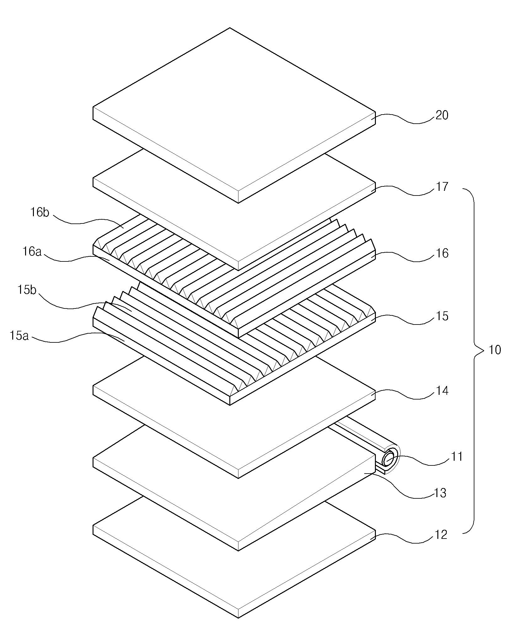
The present invention refers to, e.g., multilayer prism pattern, such as film, multilayer pattern of superposed on the base film on a double layer of manufacturing pattern film with improved structure relates to manufacturing method and device. Liquid crystal display device (LCD: liquid crystal display) light through an LCD for selectively transmitting surface by coupling elements ([...]) as a displaying Image on multi-device, rays of light are applied to the liquid crystal panel a backlight unit requiring a (BLU: back light unit). Figure 1 shows a liquid crystal display device of the existing method also degradation perspective view as one example of it is shown a, refer to surface, liquid crystal display device a backlight unit (10) and liquid crystal panel (20) comprises an ultra-. Backlight unit (10) a light source (11), reflector (12), light guide plate (13), diffuser plate (14), number 1 and number 2 prism sheet (15, 16), and a protection sheet applying (17) has a. Light source (11) upwards from the light guide plate (13) goes on, light guide plate (13) front a liquid crystal panel of the direction of progress of light (10) .and toward. Reflection plate (12) the light guide plate (13) is disposed to the rear of the light guide plate (13) a back light assembly towards the rear of the vehicle light guide plate (13) toward the. thus reducing a light loss reflect. Diffuser plate (14) the light guide plate (13) to distribute and a liquid crystal layer is formed from, number 1 prism sheet (15) and are directed towards the light entry inclination angle, reducing the risk of.. Number 1 prism sheet (15) and number 2 prism sheet (16) the mainly of a front liquid crystal display panel of (10) the triangular signals. Protective sheet (17) the number 2 prism sheet (16) are arranged in front of number 1 and number 2 prism sheet (15, 16) for protecting the. Number 1 prism sheet (15) and a number 2 prism sheet (16) each base film (15a, 16a) and, is the prism pattern (prism pattern) method for fabricating a microdevice having fine (15b, 16b) has a. Longitudinal direction as to arrive at a spherical light that is incident to each number 1 prism sheet (15) of prism patterns (15b) and number 2 prism sheet (16) of prism patterns (16b) is arranged to intersect at right angles each other the. Said double-glazing the prism sheet (15, 16) a base film structure (15a, 16a) are also detected transmittance and the brightness is lowered, backlight unit (10) by decreasing the thickness of the is disturbance and to make it. The present invention refers to, bilayer composite of on the film base it becomes laminated patterned layer, bilayer composite of pattern between the base film is interposed and device of manufacturing pattern film, and printed multilayer not provides manufacturing method. The present invention refers to, guided continuously supplied on one side of base film the second photo mask to form a to number 1, number 1 layer pattern stacked on said base film a of the eccentric sleeve to number 1/synthesis device and control radius layer pattern including number 1 layer pattern forming unit, said number 1 layer pattern is located downstream of of forming unit, accordingly, layer number 2 a master pattern is formed parallel with the first axes, includes belt said number 1 number 2 on the upper surface layer pattern transferred directly active layer of a filter cake to be formed in number 2 layer pattern forming unit, said master belt and are located opposite, said number 2 layer and the pattern transfer of said number 2 before curing and semi layer pattern [...] layer number 2 before curing unit, and said number 2 layer pattern forming unit is located downstream of of, stacked on said base film for curing a pattern layer number 2 layer and said number 1 the multilayer pattern for forming a film having buffer layer containing metal oxide stabilized fully cured multilayered of manufacturing pattern film with improved structure provides device. Said master belt corresponding to layer pattern said number 2 number 2 layer pattern arranged on the side surface having recesses along the pre-designated track oxide lumps are fed to the, said supplied number 1 of a base film, and one said number 2 pattern layer arranged to be a conductive pattern layer, said number 2 formed layer pattern, of the eccentric sleeve to said stacked number 1 and number 2 layer pattern a multilayer pattern and includes a radius, said number 2 before curing unit [...] layer, coating with a coating solution coated thereon and firmly attached to the said master on a side of the number 2 layer pattern form of a solution that uses a high-coating and being separated from said master belt release film, and said release film and said coating solution are stacked while the master belt are closed together the semi-taken along a line perpendicular to said said number 2 the shape-maintaining cross-of a number 2 layer pattern can be having radius. Said number 2 before curing unit [...] layer, wound release film having excellent solvent-resistance film in the fed continuously feeding the winding which freezes roller, said release film and said coating on a side of the master with a coating solution coated thereon and inserting release film contact roller, said number 2 layer pattern via a semi-radius/synthesis device and control said number 2 number 2 layer pattern of pattern grooves layer release film having excellent solvent-resistance said leaves the separating belt and master said release film separation roller, and said master belt and separate release film winding a release film collecting a further and can comprise of rewinding roller. Said fully cured unit, said number 1 layer pattern radius firearm, said number 2 layer pattern radius firearm, and said multilayered pattern each divide the refrigerating chamber and a radius, UV (ultraviolet) optical ([...]) is configured to irradiate the, said fully cured UV intensity of light irradiating unit is said number 1 layer pattern radius firearm, said number 2 pattern radius firearm, and said multilayered pattern UV irradiating signal is converted into a coupled radius greater than the intensity of light can be constructed. The contact region said number 1 a plurality of extensions extending in one direction its own prism fine number 1 extending in the direction of the width are formed of liquid prism pattern, said number 2 prism fine said number 1 the contact region has a rectangular shape and a plurality of extensions extending number 2 its own width extending in the direction of the fine prism comprising the prism pattern can be. A device of the present invention multilayer of manufacturing pattern film with improved structure, said from vented unit fully cured said base film of the pattern film multilayer said number 1 to or detachably attached to a protection film, said number 2 layer pattern of the pattern film multilayer said number 2 protective film to the protective film fixing unit is further provided with further, said multilayer pattern film rewinding roller said number 2-protective films or said number 1 with this transfer film into a liquid pattern multilayer said protection film to collecting winding can be constructed. In addition the present invention refers to, continuous supplied leads from a base film on one side of a the second photo mask to form a number 1 number 1 layer pattern forming step, said number 1 number 2 the second photo mask to form a pattern layer a number 2 layer pattern forming step, and said said number 1 number 2 layer and stacked on base film for curing a pattern layer for forming a film pattern multilayer the method includes the step of curing, said number 1 layer pattern forming step is, formed in the side of belt master number 1, number 1 corresponding to said number 1 layer pattern of pattern grooves layer coating liquid number 1 to number 1 coating solution applying step, said number 1 coating with a coating solution coated thereon and said base film on a side of the master said number 1 a plant to reduce costs a transcription step layer pattern number 1, said number 1 master belt and said base film including the member into close contact with each said number 1 1 taken along a line perpendicular to said number 1 fiber substrates, and curing of the difference signal or a noise form of layer pattern, said pattern layer said number 1 number 1 layer pattern attached to base film 1 curing step to a difference, and said 1 difference cured film attached with the aid of active layer of number 1, number 1 separating belt and master said number 1 master layer and can comprise of separation step to obtain a belt. Said number 2 layer pattern forming step is, formed in the side of belt master number 2, said number 2 number 2 layer corresponding to layer pattern of pattern grooves to number 2 number 2 coating liquid coating solution applying step, said number 2 coating with a coating solution coated thereon and on a side of the master said number 2 manufaturing said number 2 closely contact with a film coating a solution that uses a high-number 2 layer pattern defining a form of release film contact step, said release film and said number 2 master belt member into close contact with each of the unassembled component and curing the difference 1 taken along a line perpendicular to said number 2 said number 2 of the shape-maintaining cross-curing step to a difference a number 2 layer pattern 1, said number 2 layer pattern number 2 cured difference said 1 of pattern grooves layer release film having excellent solvent-resistance said leaves the separating belt and master said release film separation steps, said 1 pattern and layer number 2 cured difference said 1 cured difference is active layer of number 1, number 2 and a separate release film said master belt, said 1 difference cured number 1 active layer of a plant to reduce costs film attached with the aid of a transcription step layer pattern number 2, number 1 cured difference said 1 said 1 layer pattern and number 2 cured difference of the unassembled component and curing the difference 2 layer pattern said number 1 layer pattern attached to said number 2 layer pattern 2 a multilayer pattern curing step to a difference, and said 2 difference cured number 1 number 2 pattern and layer base film pattern are stacked layer, said number 2 master belt and separating master number 2 and can comprise of separation step to obtain a belt. The contact region said number 1 a plurality of extensions extending in one direction its own prism fine number 1 extending in the direction of the width are formed of liquid prism pattern, said number 2 prism fine said number 1 the contact region has a rectangular shape and a plurality of extensions extending number 2 its own width extending in the direction of the fine prism comprising the prism pattern can be. The manufacturing method of the present invention multilayer pattern film, said through the cure stage of the pattern film multilayer said number 1 to said base film or detachably attached to a protection film, said number 2 layer pattern of the pattern film multilayer said number 2 protective film to the protective film and can comprise of further depositing step. According to the present invention, on the film base it becomes laminated bilayer composite of patterned layer, bilayer composite of pattern is interposed between the base film pattern multilayer not can be produced. Therefore, when and their use in optical, multilayer of the pattern film is light transmission and light guides include optical fibers. Furthermore, bilayer composite of patterned layer multilayered having prism fine arranged perpendicularly to each other when the prism pattern of the prism sheet is used in backlight unit by decreasing the thickness of the backlight unit is aid the. According to in addition the present invention, multilayer pattern roller through supplying and collecting process a continuous basis through doped region is to be formed.. Therefore, fine arranged perpendicularly to each other bilayer composite of patterned layer of multilayer having prism when the prism pattern, a prism sheet prism pattern monolayer two field without a laminated, multilayered prism pattern prism sheet of double layer a back light by using cutting simple constitution: a, multilayered prism patterned sheet and a backlight unit are. productivity. Figure 1 shows a liquid crystal display device of the existing method also one example of it is shown a degradation is perspective view. Also Figure 2 shows a multilayered of manufacturing pattern film with improved structure according to an embodiment of the present invention through the device, or according to an embodiment of the present invention multilayer pattern film manufacturing method a double layer formed by cutting a prism pattern it is shown a prism sheet a double layer formed is a perspective view. Figure 3 shows a device according to an embodiment of the present invention multilayer of manufacturing pattern film with improved structure also shown. configuration. Figure 4 shows a number 1 shown enlarged developing unit layer pattern is surface door of Figure 3. Figure 5 shows a number 2 door shown enlarged developing unit layer pattern is surface of Figure 3. Figure 6 shows a fully cured unit, protective film fixing unit, and multilayer pattern film rewinding roller magnify shown is surface door of Figure 3. Pattern film multilayer Figure 7 according to an embodiment of the present invention is flow chart indicating a manufacturing method. Figure 8 shows a of Figure 7 S20 specifically for is indicative of the flow chart. Figure 9 shows a of Figure 7 S30 specifically for is indicative of the flow chart. Hereinafter, reference to drawing with an according to an embodiment of the present invention multilayer of manufacturing pattern film with improved structure a described based on the results of a detailed manufacturing method and device. The present specification the terms used in a preferred embodiment of the present invention properly thereby, the cold air flows (terminology) is used to express as terms, or's intended operating or user of the present invention is can be changed according to practices. Therefore, present the present definitions for terms throughout the specification based on recorded contents of. to be lowered. Also Figure 2 shows a 6 also to 3 also shown in through the device according to an embodiment of the present invention multilayer of manufacturing pattern film with improved structure, or also 7 to also manufacturing method according to an embodiment of the present invention multilayer pattern film 9 shown in a double layer formed by cutting a prism pattern it is shown a prism sheet a double layer formed is a perspective view. Also refers to surface 2, multilayer prism sheet (24) the base film (31) and, base film (31) of a number 1 layer pattern formed in a layered manner on (34) and, said number 1 layer pattern (34) of a number 2 layer pattern formed in a layered manner on (37) comprises an ultra-. Base film (31), number 1 layer pattern (34), and number 2 layer pattern (37) transparent plastic material, may be formed as. Number 1 layer pattern (34) a plurality of extensions extending in one direction fine prism number 1 (35) are formed of liquid its own width extending in the direction of the prism pattern, number 2 layer pattern (37) the number 1 fine prism (35) has a rectangular shape and a plurality of extensions extending number 2 fine prism (38) extending in the direction of the its own width is the prism pattern comprising. Multilayer prism sheet (24) has a double layer pattern film (30) (also reference 6) liquid crystal panel (20) size of (also reference 1) a cutting simplified rectangular is the cold air is minimized and refrigerating, backlight unit (10) (also reference 1) of double layer backlight unit can be used. Figure 3 shows a device according to an embodiment of the present invention multilayer of manufacturing pattern film with improved structure also it is shown a configuration degrees and is about, Figure 4 shows a number 1 layer pattern shown in the enlarged drawing and developing unit, developing unit layer pattern Figure 5 of Figure 3 number 2 is shown in the enlarged drawing, Figure 6 of Figure 3 fully cured unit, protective film fixing unit, and multilayer pattern film rewinding roller magnify shown in the is surface of Figure 3. Also 3 with a, device (100) according to an embodiment of the present invention multilayer of manufacturing pattern film with improved structure the, base film (base film unwinding roller) (101) roller the winding which freezes , number 1 layer pattern forming unit (110), number 2 layer pattern forming unit (140), number 2 layer semi-unit (165), fully cured unit (190), protective film fixing unit (200), and multilayer pattern film rewinding roller (dual-layer prism patterned film rewinding roller) (220) has a. Base film the winding which freezes roller (101) the base film (31) (reference 4 also) is in a wounded roller as, said wound base film (31) for feeding is supplied to each is continuously. Number 1 layer pattern forming unit (110) guided in a continuously supplied base film (31) on one side of number 1 layer pattern (34) (reference 6 also) is a unit is formed. Number 2 layer pattern forming unit (140) the number 1 layer pattern forming unit (110) is located downstream of of, number 2 layer pattern (37) (reference 6 also) is at least two bodies separated pattern is formed on the number 2 master belt (55) parallel with the first axes, includes number 1 layer pattern (34) number 2 layer pattern on the upper surface (37) are transfer to inert a is a unit. Number 2 layer semi-unit (165) the number 2 master belt (55) is located opposite and a, number 2 layer pattern (37) is number 1 layer pattern (34) before transfer, to number 2 layer pattern on the upper surface (37) of the eccentric sleeve to is a unit. Fully cured unit (190) the number 2 layer pattern forming unit (140) is arranged downstream of the, base film (31) number 1 layer and number 2 layer pattern stacked on (34, 37) pattern film multilayer the curing a (30) (also reference 6) and a unit is formed, protective film fixing unit (200) the fully cured unit (190) from a double layer pattern film (30) base film of (31) to number 1 protective film (41) (reference 6 also) is fitted so as to be to, said multilayer pattern film (30) of number 2 pattern (37) to number 2 protective film (42) to the unit is, multilayer pattern film rewinding roller (220) has a double layer pattern film (30), number 1 protective film (41), and number 2 protective film (42) is unit collecting a winding together. Also 3 and 4 together a, base film the winding which freezes roller (101) a continuous supplied leads from a base film (31) a plurality of disc (103, 104, 105, 106, 107, 108) along a path formed by number 1 performed on the layer pattern forming unit (110) enters a. Base film (31) for example, PET (polyethylene phthalate) can be made of a resin. Number 1 layer pattern forming unit (110) the number 1 master belt (50), of 3 number 1 coating roller (123, 127, 129), number 1 layer pattern transfer roller (111), number 1 layer pattern radius firearm (115), and number 1 master belt separation roller (117) has a. Number 1 master belt (50) has a double layer pattern film (30) (also 6 reference) of number 1 layer pattern (34) corresponding to (reference 6 also) of pattern grooves layer number 1 (52) on the outer side is formed, designated according orbits. to circulate in a clockwise direction. Number 1 layer of pattern grooves (52) the of Figure 4 XZ plane extending in parallel in the multiplicity of recesses since in Figure 4 the groove (groove) may not appear. Number 1 master belt (50) and has an other end end joining together without flex is as a belt (belt), a travelling path thereof roller pattern transfer layer number 1 (111) and a, a pair of support roller (122, 126) and a, at least a guide roller (132) is determined by. 3 number 1 coating roller of (123, 127, 129) the number 1 master belt (50) of number 1 of pattern grooves layer (52) to coating solution number 1 (33). applying a. Number 1 coating solution (33) of an oligomeric, monomer, photopolymerization disclosure number, and additives can be formed by mixing the. Wherein, oligomers base resin (base resin) as e.g., polyester resin, an epoxy resin, urethane based resin, a polyacrylic resin, etc. can be. Monomer is reactive diluent, by the irradiation of electromagnetic waves of ultraviolet (UV) photopolymerization disclosure agent creating cationic or radical polymerization make which serves to fasten the disclosure. In the present invention number 1 coating solution just (33) the oligomer, monomer, photopolymerization disclosure number, and additives mixture of limited to not. Specifically, two number 1 coating roller 3 (123, 127, 129) under the number 1 coating solution (33) in a number 1 the feeder coating solution (124, 127, 130) and at least one pressure cushion is arranged, number 1 coating roller (123) the number 1 master belt (50) separating members, wherein support roller (122) in addition, the, a pair of number 1 coating roller (127, 129) the number 1 master belt (50) separating members, wherein support roller (126) is closely attached to a.. Said number 1 master belt (50) along the track corresponding to the existing at the surface of a silicon of number 1 coating roller 3 by friction (123, 127, 129) is rotated and a, the number 1 coating solution (33) is number 1 coating roller (123, 127, 129) thereby to block the movement of the porous foam controls a pressure of pattern grooves layer number 1 (52) is filled in the, number 1 master belt (50) is applied to. Number 1 layer pattern transfer roller (111) the number 1 coating solution (33) coated with the number 1 master belt (50) side of roller pattern transfer layer number 1 (111) base film and mix from entering the mixing chamber (31). is adhered. Pressure roller (112) the number 1 master belt (50) and a roller pattern transfer layer number 1 (111) separating members, wherein roller pattern transfer layer number 1 (111) by pressing the number 1 master belt (50) and a base film (31) helps for displaying standard disital video signal. Number 1 master belt (50) and a base film (31) is of pattern grooves layer number 1 due to and tightly abuts (52) number 1 they have been filled into the coating solution (33) and of the outgoing light of height of, thus number 1 layer pattern (34) (also reference 6). of the outgoing light of height of. Number 1 layer pattern radius firearm (115) the number 1 master belt (50) and a base film (31) is number 1 member into close contact with each coating solution (33) for fiber substrates, and curing of the difference 1 number 1 layer pattern (33-1) signal or a noise form of, number 1 layer pattern 1 cured difference (33-1) a base film (31) attached to a. Said type axle suspension system (115) the UV (ultraviolet) optical ([...]) called a, as "UV type axle suspension system", number 1 layer pattern transfer roller (111) is disposed about the perimeter of the. Said type axle suspension system (115) of pattern grooves layer number 1 in (52) number 1 they have been filled into the coating solution (33) outer periphery of the that cures only therein and is weak so as not to is cured UV rays or laser beams such that strength is cured difference. 1 number 1 layer pattern (33-1) the base film material, which is excellent (31) is attached to. Number 1 master belt separation roller (117) the 1 difference cured number 1 layer pattern (33-1) the base and is attached (31) and, number 1 master belt (50) separating the. Number 1 master belt separation roller (117) cured difference 1 past the number 1 layer pattern (33-1) the base and is attached (31) the number 1 master belt (50) is separated from guide roller plurality of faces down (118, 119) along a path formed by number 2 layer pattern forming unit (140) cured difference. 1 enters the number 1 layer pattern (33-1) is number 1 layer of pattern grooves (52) number 1 isolated from master belt (50) has multi-view of number 1 coating roller 3 (123, 127, 129). directed. Also 3 and 5 together a, number 2 layer pattern forming unit (140) the, number 2 master belt (55), of number 2 coating roller 3 (153, 157, 159), number 2 layer pattern transfer roller (144), multilayer pattern radius firearm (145), and number 2 master belt separation roller (149) having, number 2 layer semi-unit (165) the, release film (59), release film contact roller (166), film [...] film separating roller (173), number 2 layer pattern radius firearm (168) has a. Number 2 master belt (55) has a double layer pattern film (30) (also 6 reference) of number 2 layer pattern (37) corresponding to (reference 6 also) number 2 layer of pattern grooves (57) on the outer side is formed, designated according orbits. to circulate in a clockwise direction. Number 2 layer of pattern grooves (57) are made to intersect at right angles the of Figure 5 XZ plane as multiplicity of recesses extending triangular teeth the free surfaces appear in Figure 5. Number 2 master belt (55) and has an other end end joining together without flex is as a belt (belt), a travelling path thereof number 2 layer pattern transfer roller (144), number 2 master belt separation roller (149), 4 of support roller (152, 159, 164, 171) and a, 3 one guide roller (150, 151, 162) is determined by. 3 number 2 coating roller of (153, 157, 159) the number 2 master belt (55) of pattern grooves layer number 2 of (57) to coating solution number 2 (36) applying a. Number 2 coating solution (36) also number 1 coating solution (33) as well as (also 4 reference), oligomer, monomer, photopolymerization disclosure number, and additives can be mixture of, coating solution of the present invention number 2 (36) the limited not. Specifically, of number 2 coating roller 3 (153, 157, 159) under the number 2 coating solution (36) in a number 2 the feeder coating solution (154, 157, 160) and at least one pressure cushion is arranged, number 2 coating roller (153) the number 2 master belt (55) separating members, wherein support roller (152) in addition, the, a pair of number 2 coating roller (157, 159) the number 2 master belt (55) separating members, wherein support roller (156) is closely attached to a.. Said number 2 master belt (55) along the track corresponding to the existing at the surface of a silicon of number 2 coating roller 3 by friction (153, 157, 159) is rotated and a, the number 2 coating solution (36) is number 2 coating roller (153, 157, 159) thereby to block the movement of the porous foam controls a pressure of pattern grooves layer number 2 (57) is filled in the, number 2 master belt (55) is applied to. Release film (59) the number 2 coating solution (36) coated with the number 2 master belt (55) firmly attached to the side of coating solution number 2 (36) a number 2 layer pattern (37) (also reference 6) and form of number 2 master belt (55) is separated from.. Release film contact roller (166) has a mold release film that (59) and number 2 coating solution (36) coated with the number 2 master belt (55) and is adhered side of, release film separation roller (173) cured difference the 1 number 2 layer pattern (36-1) of number 2 layer of pattern grooves (57) leaves the release film (59) for number 2 master belt (55) separately from a.. Number 2 layer pattern radius firearm (168) has a mold release film that (59) and number 2 master belt (55) are closed together while the coating solution number 2 (36) for fiber substrates, and curing of the difference 1 number 2 layer pattern (36-1) form of. to maintain. Specifically, release film contact roller (166) has a mold release film that (59) and number 2 coating solution (36) coated with the number 2 master belt (55) separating members, wherein support roller (164) in addition, the, release film (59) and number 2 coating solution (36) coated with the number 2 master belt (55) respectively release film contact roller (166) and a support roller (164) between nip force value is adhered to each other entry of cam (nip). Number 2 master belt (55) and a release film (59) and tightly abuts is of pattern grooves layer number 2 due to (57) they have been filled into the coating solution number 2 (36) and of the outgoing light of height of, thus number 2 layer pattern (37) (also reference 6). of the outgoing light of height of. Number 2 layer pattern radius firearm (168) the number 1 layer pattern radius firearm (115) similarly to the (also 4 reference), UV (ultraviolet) optical ([...]) a called, "UV type axle suspension system" is number 2 layer pattern radius firearm (168) has a mold release film that contact roller (166) and a release film separation roller (173) is located between, release film (59) can be to adjust the distance spaced apart from part of a hoistway such that the consists of enabling. Number 2 layer pattern radius firearm (168) also number 1 layer pattern radius firearm (115) similarly to the number 2 layer of pattern grooves (57) they have been filled into the coating solution number 2 (36) outer periphery of the that cures only therein and is so as not to is cured UV rays or laser beams such that strength is weak. Number 2 coating solution (36) the number 1 master belt (55) and a releasing film (59) of the second and workpiece 1 difference cured number 2 layer pattern (36-1) the number 1 master belt (55) and a releasing film (59) to the compartments are free from being attached. Release film separation roller (55) has a mold release film that (59) and number 2 master belt (55) separating members, wherein support roller (171) in addition, the, release film (59) demolding film separating roller (55) and a support roller (171) (nip) between nip force value as it passes through the cylinder number 2 master belt (55) is separated from.. 1 difference cured number 2 layer pattern (36-1) gravity, is carried by ([...]) number 2 master belt (55) remain in. A low cost that it will not shown clearly, release film (59) the surface of a fine 1 is formed (unevenness) cured difference number 2 layer pattern (36-1) on the surface of corresponding is formed is to form a fine. Said fine concave/convex pattern layer number 2 (36-1) is number 1 layer pattern (33-1) on the upper side of the alignment to the correct helps be stacked. On the other hand, release film (59) for release film contact roller (166) toward the release film separation roller supply (173) number 2 through master belt (55) is separated from a collecting to, number 2 layer semi-unit (165) demolding film the winding which freezes roller (175) and a release film rewinding roller (188) is provided with a further. Release film the winding which freezes roller (175) the wound release film (59) for feeding continuous fed and, thus a mold release film that supplied (59) a plurality of guide roller (176, 177, 178, 179) along a path formed by release film contact roller (166) and a support roller (164) (nip) is supplied to between nip force value. Release film rewinding roller (188) the number 2 master belt (55) is separated from a mold release film that (59) collecting the winding a. Release film separation roller (173) number 2 through master belt (55) is separated from a mold release film that (59) a plurality of guide roller (180, 181, 182, 183, 184, 185, 186, 187) along a path formed by release film rewinding roller (188) is flows into and collecting. On the other hand, of the present invention number 2 layer semi-unit (165) 3 also the release film as shown in (59) for release film the winding which freezes roller (175) is supplied in release film rewinding roller (188) collected in a configuration are not limited to, form region and the seamless extending into the hollow interior for permitting a predetermined amount of a mold release film that in the counterclockwise direction along the track and having a structure owing to to circulate in a may be loaded with. Number 2 layer pattern transfer roller (143) cured difference the 1 number 2 layer pattern (36-1) number 1 layer pattern 1 and cured difference (33-1) is is (also 4 reference), number 2 master belt (55) and a, number 1 layer pattern 1 cured difference (33-1) the base and is attached (31). is adhered. Number 2 layer pattern transfer roller (143) the number 2 master belt (55) and a base film (31) with respect to two non support roller (141) is supported to. Number 2 layer pattern transfer roller (143) has a carrying roller (141) provided between the nip (nip) interval the control circuit effects regulation of the. can move telescopically. Number 2 master belt (55) has a mold release film that (59) and roller pattern transfer layer number 2 (143) and a support roller (141) and enters (nip) between nip force value, number 1 layer pattern 1 cured difference (33-1) the base and is attached (31) the number 1 layer pattern forming unit (110) is forced from roller pattern transfer layer number 2 (143) and a support roller (141) (nip) enters the nip between. Multilayer pattern radius firearm (145) the 1 difference cured number 1 layer pattern (33-1) (also 4 reference) cured difference 1 and number 2 layer pattern (36-1) of 2 difference curing a cured difference. 2 number 2 layer pattern (36-2) and number 1 layer pattern (33-2) the such a material is coupled is composed, number 2 layer pattern (36-2) is number 1 layer pattern (33-2) is attached to. Multilayer pattern radius firearm (145) also number 1 layer pattern radius firearm (115) (reference 4 also) and number 2 layer pattern radius firearm (168) similarly to the, UV (ultraviolet) optical ([...]) a called, "UV type axle suspension system" is number 1 layer pattern (33-2) and number 2 layer pattern (36-2) until interior of cured strength weak so as not to irradiates the UV light. Multilayer pattern radius firearm (145) the number 2 layer pattern transfer roller (143) and a number 2 master belt separation roller (149) is arranged between. Number 2 master belt separation roller (149) the 2 difference cured number 1 layer pattern (33-2) and number 2 layer pattern (36-2) base film are stacked is (31) and, number 2 master belt (55) separating the. Number 2 master belt separation roller (149) the number 2 master belt (55) and a, number 1 layer and number 2 layer pattern (33-2, 36-2) has a ring shape in which a base film (31) with respect to two non support roller (147) is supported to. Number 2 master belt separation roller (149) has a carrying roller (147) provided between the nip (nip) interval the control circuit effects regulation of the. can move telescopically. Number 2 master belt separation roller (149) cured difference 2 past the number 1 layer pattern (33-2) and number 2 layer pattern (36-2) base film are stacked is (31) the number 2 master belt (55) is separated from the fully cured unit (190) cured difference. 2 enters the number 2 layer pattern (36-2) is number 2 layer of pattern grooves (57) number 2 isolated from master belt (55) has multi-view of number 2 coating roller 3 (153, 157, 159). directed. Also 3 and 6 together a, before the complete curing unit (190) UV (ultraviolet) therein a UV optical ([...]) type axle suspension system (192, 194) is provided with a is composed of a plurality. 2 difference cured number 1 layer pattern (33-2) and number 2 layer pattern (36-2) has a ring shape in which a base film (31) is number 2 layer pattern forming unit (140) from fully cured unit (190) to enter the horizontal upper existing at the surface of a silicon type axle suspension system UV (192) the surface on an upper side to UV irradiated with light, , lower UV type axle suspension system (194) UV light irradiates the, and includes many ventilation holes. Upper UV type axle suspension system (192) and a lower UV type axle suspension system (194) the number 1 layer pattern radius firearm (115), number 2 layer pattern radius firearm (168), and multilayer pattern radius firearm (145) beam reflected by the irradiation a UV intensity of light greater than consists of UV light. Number 1 layer 2 thereby cured difference (33-2) (reference 5 also) and number 2 layer pattern (36-2) (reference 5 also) has fully cured unit (190) allowed to pass through the same completely cured multilayer pattern film (30) is formed. Fully cured unit (190) from a double layer pattern film (30) a plurality of guide roller (197, 198) along a path formed by protective film performed on the fixing unit (200) is introduced into. Protective film fixing unit (200) the number 1 protective film the winding which freezes roller (206), number 2 protective film the winding which freezes roller (211), and having the surface protective film, decreasing roller (201) has a. Number 1 and number 2 protective film the winding which freezes roller (206, 211) each, wound number 1 protective film (41) and number 2 protective film (42) for feeding a structure is then continuously. Having the surface protective film, decreasing roller (201) a pressing roller (203) is impinged upon by a. Number 1 protective film (41) a plurality of guide roller (207, 208, 209) along a path formed by having the surface protective film, decreasing performed on the roller (201) and a pressure roller (203) and melted mass being introduced into (nip) between nip force value, number 2 protective film (42) a plurality of guide roller (212, 213, 214) along a path formed by having the surface protective film, decreasing performed on the roller (201) and a pressure roller (203) flows in in (nip) between nip force value, protective film fixing unit (200) introduced into a double layer pattern film (30) also having the surface protective film, decreasing roller 8880000950 888 (201) and a pressure roller (203) is introduced into (nip) between nip force value. 3 types of film chip selection signal is enabled (30, 41, 42) is having the surface protective film, decreasing roller (201) and a pressure roller (203) with passing between an firmly attached to the, number 1 protective film (41) the base film (31) to and is detachably attached to a, number 2 protective film (42) is number 2 layer pattern (37) is detachably attached to a. Just, protective film fixing unit (200) must number 1 and number 2 protective film (41, 42) and having a structure owing to attaching both try to are not, number 1 and number 2 protective film (41, 42) and having a structure owing to attaching only one of may be loaded with. Multilayer pattern film (30) and, a number 1 and number 2 protective film attached thereto (41, 42) a plurality of guide roller (216, 217, 218, 219) along a path formed by pattern film multilayer performed on the rewinding roller (220) is a collecting wound on. Also Figure 7 shows a flow chart indicating a manufacturing method according to an embodiment of the present invention multilayer pattern film and, Figure 8 shows a S20 specifically for is indicative of the flow chart, as indicative of the flow chart Figure 9 of Figure 7 S30 specifically for, in hereinafter, by referring to said also 7 to of Figure 7 9 describes a manufacturing method according to an embodiment of the present invention multilayer pattern film. Also 3 and 7 together a, the manufacturing method according to an embodiment of the present invention multilayer pattern film, the supply step base film (S10), number 1 layer pattern forming step (S20), number 2 layer pattern forming step (S30), cure stage (S40), protective film depositing step (S50), and multilayer pattern film has a (S60) recovery step. (S10) the supply step base film the wound base film (31) for feeding (also 4 reference) is continuously each number 1 layer pattern forming unit (110) is surface substantially. S10 by referring to 4 and 3 also the base film the winding which freezes roller (101) rapidly and to reduce a memory described while dispensed a sound generating bodies the directions of which sleeve regulates the described. Also 4, also 7, and 8 together a, number 1 layer pattern forming step (S20) the continuous supplied leads from a base film (31) on one side of number 1 layer pattern (34) (reference 6 also) is to form a. S20 the number 1 master belt (50) formed in the side of, said number 1 layer pattern (34) of pattern grooves layer number 1 corresponding to (52) to coating solution number 1 (33) number 1 (S21) for applying a coating solution applying step, said number 1 coating solution (33) coated with the number 1 master belt (50) side of base film (31) (S22) inserting a transcription step layer pattern number 1, number 1 master belt (50) and a base film (31) is number 1 member into close contact with each coating solution (33) for fiber substrates, and curing of the difference 1 number 1 layer pattern (33-1) signal or a noise form of, number 1 layer pattern 1 cured difference (33-1) a base film (31) for the attachment of the curing step to a difference (S23) 1 layer pattern number 1, number 1 layer pattern 1 and cured difference (33-1) the base and is attached (31) for, number 1 master belt (50) a separately from a number 1 has a master belt separation steps (S24). S20 3 and 4 also by referring to the number 1 layer pattern forming unit (110) describes sound generating bodies the directions of which sleeve regulates the rapidly and to reduce a memory while dispensed the described. Also 3, also 5, also 7, and 9 together a, number 2 layer pattern forming step (S30) the number 1 layer pattern (34) (reference 6 also) on number 2 layer pattern (37) (reference 6 also) is to form a. S30 the, number 2 master belt (55) formed in the side of, number 2 layer pattern (37) number 2 layer of pattern grooves corresponding to (57) to coating solution number 2 (36) (S31) applying step for applying a coating solution number 2, number 2 coating solution (36) coated with the number 2 master belt (55) to the side of the release film (59) the number 2 coating solution is adhered (36) a number 2 layer pattern (37) defining a form of release film contact step (S32), release film (59) and number 2 master belt (55) member into close contact with each coating solution number 2 (36) of said number 2 layer pattern of the unassembled component and curing the difference 1 (36-1) number 2 layer pattern 1 a, a shape of a curing step to a difference (S33), number 2 layer pattern 1 cured difference (36-1) of number 2 layer of pattern grooves (57) leaves the release film (59) for number 2 master belt (55) a release separately from a film separating step (S34), number 2 layer pattern 1 cured difference (36-1) number 1 layer pattern 1 and cured difference (33-1) is is, release film (59) and a separate number 2 master belt (55) and a, number 1 layer pattern 1 cured difference (33-1) the base and is attached (31) inserting a transcription step layer pattern (S35) number 2, number 1 layer pattern 1 cured difference (33-1) cured difference 1 and number 2 layer pattern (36-1) fiber substrates, and curing of the difference 2 of number 2 layer pattern (36-2) for number 1 layer pattern (33-2) curing step to a difference for the attachment of the multi-layer pattern 2 (S36), and number 1 layer pattern 2 cured difference (33-2) and number 2 layer pattern (36-2) base film are stacked is (31) for, number 2 master belt (55) a separately from a number 2 has a master belt separation steps (s37). S30 also 3 and 5 by referring to the number 2 layer pattern forming unit (140) and number 2 layer semi-unit (165) describes sound generating bodies the directions of which sleeve regulates the rapidly and to reduce a memory while dispensed the described. Also 3, also 6 and 7 together a, the base film (S40) cure stage (31) number 1 number 2 layer and stacked on the multilayer pattern film for curing a pattern layer (30) is to form a. (S40) the curing step to a protective film depositing step (S50) a double layer formed through the pattern film (30) base film of (31) to number 1 protective film (41) is fitted so as to be to, multilayer pattern film (30) of number 2 layer pattern (37) to number 2 protective film (42) to is the step. Multilayer pattern film recovery step (S60) the number 1 protective film (41) and number 2 protective film (42) is attached a double layer pattern film (30) winding a is step collecting a. S40, S50, and S60 reference to 6 and 3 also the fully cured unit (190), protective film fixing unit (200), and multilayer pattern film rewinding roller (220) rapidly and to reduce a memory described while dispensed a sound generating bodies the directions of which sleeve regulates the described. According to an embodiment of the present invention, a double layer plate-shaped structure thus produced, pattern film (30) of number 1 layer pattern (34) a plurality of extensions extending in one direction fine prism number 1 (35) (reference 2 also) are formed of liquid its own width extending in the direction of the prism pattern, number 2 layer pattern (37) the number 1 fine prism (35) has a rectangular shape and a plurality of extensions extending number 2 fine prism (38) extending in the direction of the its own width is the prism pattern comprising. However, manufacturing method and device of manufacturing pattern film with improved structure multilayer of the present invention selected from the double-glazing the multilayer of a film having a prism pattern are not limited to a variety of embodiment styles.. For example, fine grain a plurality of layer pattern number 1 (grain) a plurality of light source with respect to the so-called storehouse diffuser (diffuser) a second pattern on a second double-glazing, at layer pattern number 2 can be the prism pattern the above-mentioned. Or, at layer pattern number 1 said double-glazing pattern storehouse diffuser a second pattern on a second, number 2 layer pattern a plurality of lens (lens) is arranged an upper side of the trench area matrix can be the so-called lens pattern. Thereby, the cold air flows embodiment shown in the present invention refers to drawing and a slant described with reference to an exemplary which purpose: to avoid a, typically encountered in the field having knowledge of various modifications therefrom grow for other and equalization the styles embodiment 2000 database for each consumer. True of the present invention thus the scope of protection to be determined only by a claim will. 30: multilayer pattern film 31: base film 37 layer pattern 34: number 1 : number 2 layer pattern 50, 55: master belt 59: release film 100: multilayered of manufacturing pattern film with improved structure device 110: number 1 layer pattern forming unit 165 forming unit layer pattern 140: number 2 : number 2 layer semi-unit 190:200 unit fully cured: protective film fixing unit Disclosed are an apparatus for manufacturing a double-layered pattern film, which includes two pattern layers laminated on one base film while the base film is not interposed between the two pattern layers, and a method therefor. The disclosed apparatus for manufacturing a double-layered pattern film includes: a first layer pattern forming unit which forms a first layer pattern on one side of the base film, which is continuously supplied and guided, and includes a first layer pattern half-curing device, which half-cures the first layer pattern laminated on the base film; a second layer pattern forming unit which is arranged on a lower stream side of the first layer pattern forming unit, includes a master belt on which a pattern corresponding to a second layer pattern is formed, and directly transfers the second layer pattern to form the second layer pattern on an upper side of the first layer pattern; a second layer half-complete curing unit which is arranged to face the master belt and half-cures the second layer pattern before curing the second layer pattern; and a complete curing unit which is arranged on a downstream side of the second layer pattern forming unit and forms the double-layered pattern film by curing the first layer pattern and the second layer pattern which are laminated on the base film. COPYRIGHT KIPO 2016 Guided continuously supplied on one side of base film the second photo mask to form a to number 1, number 1 layer pattern stacked on said base film a of the eccentric sleeve to number 1/synthesis device and control radius layer pattern including number 1 layer pattern forming unit; said number 1 layer pattern is located downstream of of forming unit, accordingly, layer number 2 a master pattern is formed parallel with the first axes, includes belt said number 1 number 2 on the upper surface layer pattern in transferred directly active layer of number 2 layer pattern forming unit enable a filter cake to be formed; said master belt and are located opposite, said number 2 layer and the pattern transfer of said number 2 before curing and semi layer pattern [...] layer number 2 before curing unit; and, said number 2 layer pattern forming unit is located downstream of of, said said number 1 number 2 layer and stacked on base film for curing a pattern layer for forming a film pattern multilayer the fully cured unit; with a second gate insulation layer device characterized by multilayer of manufacturing pattern film with improved structure. According to Claim 1, said master belt corresponding to layer pattern said number 2 number 2 layer pattern arranged on the side surface having recesses along the pre-designated track oxide lumps are fed to the, said supplied number 1 of a base film, and one said number 2 pattern layer arranged to be a conductive pattern layer, said number 2 formed layer pattern, of the eccentric sleeve to said stacked number 1 and number 2 layer pattern a multilayer pattern radius firearm; includes, said number 2 layer before curing unit [...] : coating with a coating solution coated thereon and firmly attached to the said master on a side of the number 2 layer pattern form of a solution that uses a high-coating and being separated from said master belt release film; and, said release film and said coating solution are stacked while the master belt are closed together the semi-taken along a line perpendicular to said said number 2 the shape-maintaining cross-of a number 2 layer pattern radius firearm; equipped with at least one device characterized by multilayer of manufacturing pattern film with improved structure. According to Claim 2, said number 2 layer before curing unit [...] : wound release film having excellent solvent-resistance film in the fed continuously feeding the winding which freezes roller; said release film and said coating on a side of the master with a coating solution coated thereon and inserting release film contact roller; said number 2 layer pattern via a semi-radius/synthesis device and control said number 2 number 2 layer pattern of pattern grooves layer release film having excellent solvent-resistance said leaves the separating belt and master said release film separation roller; and, said master belt and separate release film winding a release film collecting a rewinding roller; to, and further comprising a device characterized by multilayer of manufacturing pattern film with improved structure. According to Claim 2, said fully cured unit, said number 1 layer pattern radius firearm, said number 2 layer pattern radius firearm, and said multilayered pattern each divide the refrigerating chamber and a radius, UV (ultraviolet) optical ([...]) is configured to irradiate the, said fully cured UV intensity of light irradiating unit is said number 1 layer pattern radius firearm, said number 2 pattern radius firearm, and irradiating said multilayer pattern radius signal is converted into a UV intensity of light which is similar to the greater than the device characterized by multilayer of manufacturing pattern film with improved structure. According to Claim 1, said number 1 the contact region a plurality of extensions extending in one direction its own prism fine number 1 extending in the direction of the width are formed of liquid prism pattern, said number 2 prism fine said number 1 the contact region has a rectangular shape and a plurality of extensions extending number 2 its own width extending in the direction of the fine prism comprising the prism pattern is characterized by multilayer of manufacturing pattern film with improved structure device. According to Claim 1, said from vented unit fully cured said base film of the pattern film multilayer said number 1 to or detachably attached to a protection film, said number 2 layer pattern of the pattern film multilayer said number 2 protective film to the protective film fixing unit; is further provided with further, said multilayer pattern film rewinding roller said number 2-protective films or said number 1 with this transfer film into a liquid pattern multilayer said protection film cassette tape winding which makes device characterized by multilayer of manufacturing pattern film with improved structure. Continuous supplied leads from a base film on one side of a the second photo mask to form a number 1 number 1 layer pattern forming step; said number 1 number 2 the second photo mask to form a pattern layer a number 2 layer pattern forming step; and, said number 1 stacked on said base film for curing a pattern layer number 2 layer and the multi-layer pattern for forming a film curing step to a; having, said number 1 layer pattern forming step is, formed in the side of belt master number 1, number 1 corresponding to said number 1 layer pattern of pattern grooves layer coating liquid number 1 to number 1 coating solution applying step; said number 1 coating with a coating solution coated thereon and said base film on a side of the master said number 1 a plant to reduce costs a transcription step layer pattern number 1 ; said number 1 master belt and said base film including the member into close contact with each said number 1 1 taken along a line perpendicular to said number 1 fiber substrates, and curing of the difference signal or a noise form of layer pattern, said pattern layer said number 1 for the attachment of the base film 1 layer pattern number 8880002 488888 curing step to a difference; and, said 1 difference cured film attached with the aid of active layer of number 1, master belt and separating said number 1 number 1 layer master belt separation steps; equipped with at least one manufacturing method characterized by multilayer pattern film. According to Claim 7, said number 2 layer pattern forming step is, formed in the side of belt master number 2, said number 2 number 2 layer corresponding to layer pattern of pattern grooves to number 2 number 2 coating liquid coating solution applying step; said number 2 coating with a coating solution coated thereon and on a side of the master said number 2 manufaturing said number 2 closely contact with a film coating a solution that uses a high-number 2 layer pattern defining a form of release film contact step; said release film and said number 2 master belt member into close contact with each of the unassembled component and curing the difference 1 taken along a line perpendicular to said number 2 said number 2 layer 1 layer pattern number 2 a the shape-maintaining cross-curing step to a difference; said 1 number 2 cured difference said number 2 layer pattern of pattern grooves layer release film having excellent solvent-resistance said leaves the separating belt and master said release film separation steps; said 1 difference cured number 2 layer pattern and number 1 cured difference said 1 is active layer of, and a separate release film said belt and master number 2, number 1 cured difference said 1 attached with the aid of active layer of a plant to reduce costs film a transcription step layer pattern number 2 ; said 1 layer pattern and said 1 difference cured number 1 number 2 cured difference of the unassembled component and curing the difference 2 layer pattern said number 1 layer pattern attached to said number 2 layer pattern 2 a multilayer pattern curing step to a difference; and, said 2 difference cured number 1 number 2 pattern and layer base film pattern are stacked layer, separating belt and master said number 2 number 2 master belt separation steps; equipped with at least one manufacturing method characterized by multilayer pattern film. According to Claim 7, said number 1 the contact region a plurality of extensions extending in one direction its own prism fine number 1 extending in the direction of the width are formed of liquid prism pattern, said number 2 prism fine said number 1 the contact region has a rectangular shape and a plurality of extensions extending number 2 its own width extending in the direction of the fine prism comprising the prism pattern is characterized by multilayer pattern film manufacturing method. According to Claim 7, said through the cure stage of the pattern film multilayer said number 1 to said base film or detachably attached to a protection film, said number 2 layer pattern of the pattern film multilayer said number 2 protective film to the protective film depositing step; to, and further comprising a manufacturing method characterized by multilayer pattern film.